MISSION ADAPTIVE UAS CAPABILITIES FOR EARTH SCIENCE AND
RESOURCE ASSESSMENT
S. Dunagan a, *, M. Fladeland a, C. Ippolito a, M. Knudson a,, Z. Young a,
a
NASAAmes Research Center, Moffett Field CA USA 94035 – [email protected], [email protected], [email protected], [email protected], [email protected]
KEY WORDS: remote sensing, UAS, autopilot, flight control, sensors, hyperspectral, radiometry, magnetometry
ABSTRACT:
Unmanned aircraft systems (UAS) are important assets for accessing high risk airspace and incorporate technologies for sensor coordination, onboard processing, tele-communication, unconventional flight control, and ground based monitoring and optimization. These capabilities permit adaptive mission management in the face of complex requirements and chaotic external influences. NASA Ames Research Center has led a number of Earth science remote sensing missions directed at the assessment of natural resources and here we describe two resource mapping problems having mission characteristics requiring a mission adaptive capability extensible to other resource assessment challenges.
One example involves the requirement for careful control over solar angle geometry for passive reflectance measurements. This constraint exists when collecting imaging spectroscopy data over vegetation for time series analysis or for the coastal ocean where solar angle combines with sea state to produce surface glint that can obscure the signal. Furthermore, the primary flight control imperative to minimize tracking error should compromise with the requirement to minimize aircraft motion artifacts in the spatial measurement distribution. A second example involves mapping of natural resources in the Earth’s crust using precision magnetometry. In this case the vehicle flight path must be oriented to optimize magnetic flux gradients over a spatial domain having continually emerging features, while optimizing the efficiency of the spatial mapping task.
These requirements were highlighted in recent Earth Science missions including the OCEANIA mission directed at improving the capability for spectral and radiometric reflectance measurements in the coastal ocean, and the Surprise Valley Mission directed at mapping sub-surface mineral composition and faults, using high-sensitivity magnetometry. This paper reports the development of specific aircraft control approaches to incorporate the unusual and demanding requirements to manage solar angle, aircraft attitude and flight path orientation, and efficient (directly geo-rectified) surface and sub-surface mapping, including the near-time optimization of these sometimes competing requirements.
* Corresponding Author
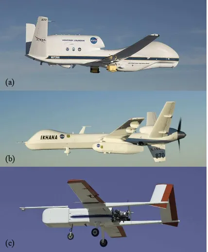
1. INTRODUCTION AND BACKGROUND The Earth Science Division within the National Aeronautics and Space Administration (NASA) collaborates with many US and international partners to observe and assess natural resources at the global scale. This involves the use of orbital, suborbital, and ground-based assets to provide measurements across a broad range of spatial and temporal scales. Unmanned aircraft systems (UAS) are playing an increasing role in enabling missions, particularly when the risk to a flight crew is unacceptably high (NRC, 2007). NASA’s Airborne Science Program has experience operating several UAS across a wide spectrum of mission capabilities ranging from global to localized scale, as illustrated in figure 1. These aircraft have been used to support missions directed at gaining better scientific understanding of the atmosphere and its processes as well as the study of terrestrial and ocean ecosystem resources. Resource assessment and mapping missions that are specifically enabled by UAS technology (Dunagan et al., 2007) include the study of coastal ocean water quality, coral reef ecosystems, algal bloom phenomena, the study of volcanoes in a pre-eruptive state (Diaz et al., 2010) , and the study of wildfire, including tactical fire management, fuel mapping, and post-fire recovery. (Ambrosia et al., 2011)
Currently available commercial UAS include many mission specific integrated sensor technologies, as well as a number of mission support technologies, including onboard data
processing, high-bandwidth line-of-sight and satellite communications to the ground, and increasingly sophisticated vehicle navigational capabilities for collision avoidance and automated takeoff and landing. The absence of traditional constraints on manoeuvrability and human life support environment, coupled with increasing automation capabilities for unconventional aircraft control for both individual and multiple collaborating aircraft, improve the potential to design more informative, efficient, and productive remote sensing flight experiments.
Flight planning for remote sensing missions is often confounded by uncertainties or anomalies in the spatial distribution of the phenomena under study or by various critical experimental parameters that are intrinsically chaotic such as weather, (e.g. cloud cover, winds, sea state, etc.) These factors may not be known a-priori, or may be dynamic with a limited temporal horizon. Effective mission execution and efficient flight data acquisition require more sophisticated models and automation tools to manage the risks associated with this uncertainty in key flight experiment parameters, and the ability of the mission to adapt to this evolving information.
NASA aircraft and satellites by enabling overlays on a common map display, plotting of near-time data, and enabling real-time communications between the science team and aircraft operators.
Figure 1. NASA UAS flown in support of Earth observations for science and applications at global (a, Global Hawk) regional
(b, Ikhana) and local (c, SIERRA) scales.
NASA’s Aeronautics Mission Directorate has recently committed significant resources towards developing the technologies that will integrate UAS of all size classes into the national airspace (NAS). While the technological capacity to design and execute quite sophisticated automated missions has long been available, there are now emerging demands and opportunities for science operations in a variety of potentially complex airspaces, and in shorter deployment windows. Therefore, it has become increasingly important for the U.S Federal Aviation Administration (FAA) and international regulatory bodies to incorporate NASA experience with UAS technology and operations in order to identify vehicle safety and operational constraints and define the certification processes that will permit these aircraft and systems of aircraft to operate safely in the national airspace.
To enable mission adaptive UAS missions the level of autonomy present on the vehicle is a key consideration for the type certification of these vehicles for normal operations within the national airspace (i.e., the need only to have reviewed and filed a flight plan, rather than pursue experimental operations permission). The FAA currently requires, and will always, require human-in-the-loop (HITL) operations on UAS operating in the general NAS. Regarding the advanced autonomy described herein, two high-level requirements must be met: 1) The autonomy must be vetted thoroughly via existing and forthcoming FAA new technology development processes for UAS (RTCA-228 MOPS in process).
2) Special “fail-down” functionality in level of autonomy must be activated during lost-link situations, where HITL is lost.
The structure of the autonomy described herein lends itself quite well to both of these high-level requirements. Firstly, the technology has been generated under NASA software/ hardware regulations, which are used to inform the Radio Technical Commission for Aeronautics (RTCA) and subsequent DO regulations forthcoming for UAS. Secondly, the hierarchical structure of the autonomy permits straight-forward step-down in autonomy to more accepted lost-link autonomous behaviour (i.e., loiter, timed return-to-base, etc).
Of the many UAS available to NASA's Airborne Science Program, the 170 kg gross weight “Sensor Integrated Environ-mental Remote Research Aircraft” (SIERRA) platform has seen the greatest variety of mission applications (Fladeland et al., 2011). In this paper we will examine two of those applications having particularly stringent requirements for flight planning and execution, and the unconventional approaches to flight control and automation that were adapted for these mission designs. In addition to the normal global positioning system (GPS) and attitude heading reference system (AHRS) sensors that provide the autopilot with the basic information it needs to keep the aircraft upright and on track to the next waypoint, we will look at incorporating additional sensors into the control loop to optimize the vehicle performance in context with specific and complex mission requirements.
The SIERRA aircraft shown in figure 1c successfully completed many science and applications missions ranging from the tropics to the arctic. In the fall of 2013 work began on an improved 200 kg variant SIERRA-B which is in the final stages of assembly and certification. Improvements include a stronger fuselage to accommodate more payload and fuel, a wet-wing fuel tank to improve range, a more powerful fuel injected engine, and a dual processor engine control unit with several levels of sensor processing capability to optimize power, fuel economy, and emissions. As with SIERRA-A, redundancy is present in several flight critical systems. Key additional features in SIERRA-B include the ability for the aircraft to localize with much higher precision utilizing Differential GPS technology, the ability for automated takeoff and landing (ATOL), and a control structure enabling the autopilot (CloudCap Piccolo-2) to operate in a hierarchical scheme with a flight executive and/or other more sophisticated control computers.
One might generalize resource management mission requirements into two classes. In one case the objective is to thoroughly map the full spatial domain in the most efficient way, subject to the constraints imposed by the payload sensors. For imaging radiometers measuring the reflected solar signal, the illuminating angle of the solar radiation can be an important constraint, particularly over water where wind driven wave effects can give rise to significant glint from the water surface, obscuring the reflectance signal from biological constituents in the water column or ecosystem features on shallow coastal bottoms. An aircraft equipped with an AHRS and accurate timing information has enough a-priori knowledge to compute the solar angle. However a more direct approach incorporates a solar angle measurement device based on modern digital camera technology. This direct approach can be more accurate and has the added advantage of providing an image record of cloud conditions, which can be quite useful for post-flight data analysis. In this context we present here a discussion of the “Ocean Color Ecosystem Assessments with Novel Instruments and Aircraft” (OCEANIA) mission designed to provide a platform for calibration and validation of water-leaving (a)
(b)
radiance and to exploit coastal ocean bio-optical measurements of phytoplankton at low altitude (100 ft) to study a seasonal fall algal bloom event in the Monterey Bay. This mission design selected for the SIERRA UAS to optimize sensor portability to respond rapidly to coastal events and missions. To test this capability, SIERRA was selected to deploy over Monterey Bay at low altitude in support of the Fall HyspIRI high altitude airborne campaign and coincident satellite overpasses. A suite of precision radiometers (Biospherical Instruments Inc.) were integrated on SIERRA to collect highly accurate apparent optical property (AOP) observations in order to derive exact water leaving spectral radiance to capture phytoplankton variability associated with the algal bloom in Monterey Bay.
The second class of adaptive mission requirements involves exploratory mapping in which the mission path is redirected in near-real time based on feedback from a designated sensor suite, which might include the primary payload. Mineral resource exploration and mapping is an example of this type, and we present here a discussion of the Surprise Valley Magnetic Mapping Mission, again using the SIERRA aircraft equipped with a precision magnetometer instrument suite. In this mission the flight line planning was manipulated in near-real time to produce flight line trajectories optimized to track and map a large magnetic anomaly of unknown location and extent, and correlates these data with subsurface fault and geothermal hydrological features.
2. COASTAL ZONE RESOURCE MAPPING MISSION 2.1 Science and Mission Requirements
Reflectance spectra from biological materials in the water column and on the ocean floor can provide important information to discriminate species, to assess water quality and turbidity, and to evaluate foundational ecosystem processes such as net primary productivity. In-situ measurements using field radiometers and calibration reflectance panels can be complex owing to transient lighting conditions resulting from variable cloud cover as well as lensing effects at the water surface. A coastal ocean remote-sensing approach to reflectance measurements must include corrections for transmission through the atmosphere, water surface, and water column. An emerging strategy for water column and benthic remote sensing in the coastal zone (Guild et al, 2011; Guild et al., 2014)) involves a payload suite comprising a hyperspectral imager capable of resolving key discriminating spectral features in the reflectance spectra, and a suite of 19-channel radiometers measuring total down-welling solar irradiance (Es), indirect sky radiance (Li) , and total upwelling radiance (Lt). If possible, an airborne sunphotometer may provide added information to help correct for atmospheric aerosols and column water vapor. These measurements are combined in an inversion algorithm to resolved water leaving radiance and ultimately improve the quality of calculated reflectance spectra of biological compounds.
The following operational parameters are germane to this discussion of flight control, and combine to provide some unique requirements for flight control and adaptive flight line planning for optimized data acquisition. While many parameters are deterministically known (e.g. ephemeris models of sun position), weather conditions affecting sea state and ocean surface glint, as well as the constantly changing solar angle pose this as a near-time adaptive mission problem.
1. Smooth aircraft translation is critical to provide uniform data spacing in the along-track spatial dimension. Stable roll and pitch, with the ground track vector and aircraft heading co-aligned provides optimal optical sampling.
2. In order to minimize surface glint into the hyperspectral imager, the aircraft must be oriented to maintain a solar elevation angle between 30 and 45 degrees, and <10 degree difference between heading and solar principal plane.
3. To minimize error in radiance inversion, the plane containing the Li and Lt radiometers must be maintained in a vertical orientation, and must be azimuthally oriented between 90 and 105° from the solar principal plane.
4. A mapping mission must provide complete coverage of the coastal zone region of interest.
5 Radiometric measurements must be obtained at altitudes suitable for reasonable remote-sensing coverage, but also at minimum safe flight altitude to reduce uncertainties in the atmospheric light path between the aircraft and sea surface.
2.2 Instruments and Flight control.
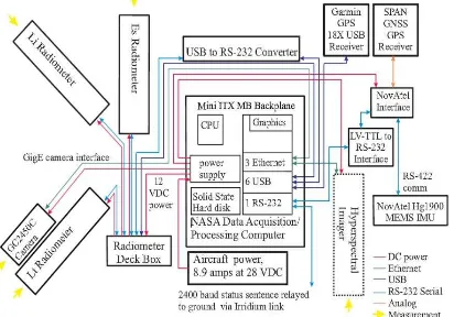
The payload components described previously are shown in the block diagram of figure 2. In addition to the primary imaging spectrometer and radiometers described above, the payload includes a scene camera co-aligned with the Lt radiometer to provide a record of sea state, with the objective of evaluating the potential for glint or wave cap contamination of the data or other surface phenomenon (e.g., foam). GPS and inertial navigation components comprising the AHRS are rigidly mounted to the imaging sensors and included in the payload data processing stream. The data acquisition system manages the acquisition and recording of all instrument data streams and provides the time stamp that permits these multiple data records to be aligned temporally and spatially with supporting measurements provided by collaborating ship and ground-based assets. The OCEANIA instrument suite did not include an on-board hyperspectral imager, focusing instead on radiometric measurements for spacecraft instrument calibration and validation. However, missions requiring high spatial and/or spectral resolution would typically include such an imager.
Figure 2. Block diagram of OCEANIA payload configuration.
cameras with dynamic range up to 120 db. This wide range permits imaging the Sun without saturation, but still provides a qualitative measurement of sky features such as clouds. This system and the detail of implementation into a mission adaptive controller design are discussed in section 4.
2.3 Flight Experiment
When SIERRA was unavailable for the OCEANIA mission the Center for Interdisciplinary Remotely-Piloted Aircraft Studies (CIRPAS) based in Monterey California was able to provide a Twin Otter aircraft that could accommodate all payload equipment. This twin-engine aircraft has the capacity to climb out on a single engine and was therefore capable of meeting the low altitude requirements for this mission.
Certification requirements for this manned aircraft precluded the implementation of any payload directed flight functionality. However we did attempt to achieve the solar angle control with the pilot in the loop. The flight plan was anchored by a set of waypoints at the northern border of the study area. A lookup table was used to determine the required headings to maintain the solar angle criteria at any particular time of day. And the pilots were instructed to attempt to fly with the wings and fuselage as flat as possible. These instructions may form the basis of the merit function derived for the optimization algorithm of an on-board flight controller.
Figure 3. OCEANIA flight lines acquired 11-5-2013 to map water leaving radiance in coastal waters.
Figure 3 presents the flight track pattern acquired for the flight test date of November 5, 2013. The ground track plot represents aircraft location received in near time through the CIRPAS RADD flight experiment tracking software, which provides the ability to monitor experimental progress similar to the NASA Mission Tools Suite described in section 1. The flight line anchor points appear as pushpins along the north border of the study area. Flight line heading was adjusted by the pilot in real time using an ephemeris-derived chart. The westerly progression of the sun is evident in the ground track angle. Individual points in the ground track are recorded at 2 second intervals. Colour coding is used to provide more information on a broad range of flight parameters obtained in real time from the Twin Otter AHRS and other supporting instrumentation. In this figure, a green colour code was used to indicate that the aircraft fuselage pitch angle was within a +/- 2 degree range, defined to be the acceptable range for the “vertical” requirement for orientation of the plane of the Li and
Lt radiometers, as discussed previously. This plot indicates that the pilots were generally able to meet this condition, but in post processing it became clear that the azimuthal orientation of this radiometer plane was more difficult to maintain within the prescribed 90 to 105 degree limits (requirement 3), supporting the argument for a more automated controller.
3. SURPRISE VALLEY MAGNETIC MAPPING MISSION
Understanding the underlying geological features of a region is a critical step in managing both mineral and groundwater resources, and is particularly important in regions where fault zones add complexity and increase the risk of societal impact from earthquakes. Remote-sensing techniques directed at inferring subsurface structure from measured gravitational and magnetic fields are finding an increasing number of applications from both aircraft and spacecraft platforms. Recent advances in the miniaturization of magnetometer instrumentation, coupled with the use of nonmagnetic materials in UAV airframe construction, provides a unique opportunity to exploit this combination
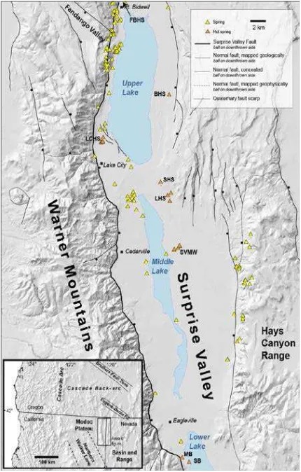
Figure 4. Fault and geothermal features in Surprise Valley, CA [from J. M. G. Glen, U. S. Geological Survey (USGS)].
Establishing these spatial correlations requires geological and geophysical mapping studies that locate subsurface structures in relationship to surface springs. These studies can include ground-based gravity and magnetic surveys, which are particularly useful for identifying buried, intra-basin structures, especially in areas where highly magnetic, dense volcanic rocks are interspersed with, and faulted against less magnetic, less dense sedimentary rock.
Ground based investigations are labor intensive and their spatial extent can be limited by impassable surface features, (e;g; marsh, dense vegetation) and inaccessible or private lands. This can result in data gaps in key areas, sometimes around active geothermal springs, where detailed surveys are most critical.
High-resolution gravity data must be collected at point locations on the ground. However, high-resolution magnetic data can be collected from the air and can provide continuous coverage (Glen et al., 2008). Prolonged low-altitude high-resolution manned aircraft surveys are dangerous, costly and relatively inflexible to changes in the survey specifications that may arise as data are collected. UAS are well suited for conducting these surveys. They can provide uniform, low-altitude, high-resolution coverage of an area without endangering a pilot and crew, and they are more easily adaptable to changes in flight plans as data are collected, potentially providing significantly improved efficiency.
The following operational requirements apply to this discussion of adaptive flight control. In this case, uncertainty in the distribution of subsurface features is the dominant emerging information that affects the adaptation of the flight plan for improved mapping efficiency.
1. The aircraft should fly at minimum safe altitude to improve the sensitivity of the magnetic field measurement. (For UAS in un-populated areas, this can be quite low.) Altitude must be known with high accuracy.
2. The magnetometer installation must be carefully calibrated to account for both hard and soft iron effects in the airframe. Composite non-magnetic airframe materials and low electrical current in the aircraft avionics and power systems, with isolated magnetometer mount points are desirable.
3. The survey flight path must update in near time to follow the strongest magnetic fields and determine the extent of the large magnetic anomaly features.
3.2 Magnetic Mapping Payload
Scientists at the United States Geological Survey (USGS), in collaboration with magnetometer equipment manufacturers have been developing miniaturized, highly sensitive instruments for use in the field from all terrain vehicles as well as UAS (Versteeg et al., 2007). Building on this capability, the composite SIERRA airframe was fitted with a modified Geometrics G-858 magnetometer system interfaced to a “common payload data system” (CPDS) as depicted in figure 5. Supporting measurements from an inertial measuring unit (IMU) interfaced to a differential global positioning system (DGPS) receiver, a high-precision three-axis magnetometer, and laser altimeter provided precise aircraft location information as required to resolve the magnetic field measurement. The aircraft autopilot telemetry system was augmented by an independent 900 MHz communications link for payload data telemetry to the ground for mapping in near time. The ground station also received DGPS correction signals from a stationary DGPS receiver.
Figure 5. SIERRA Common Payload Data System (CPDS) for Surprise Valley Mission.
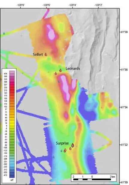
Figure 6: Magnetic residual map of a portion of the SIERRA flight data showing the location of cold (blue symbols) and hot
(red symbols) springs (from J. M. G. Glen, USGS).
3.3 Flight Experiment
more specifically, at structural transitions where the high undergoes steps, bends, or breaks. The close relationship between the springs and structure terminations revealed by this study is unprecedented. Near-time telemetry of magnetic data to the ground permitted the formulation of an emerging view of the dominant structures, but this information was not linked directly to a flight controller. This process naturally points toward incorporating the near time measurement into a searching algorithm with a more direct linkage to an autonomous flight planner.
4. MISSION ADAPTIVE AUTONOMY 4.1 Unconventional sensors
We have described the use of unconventional sensors as inputs to a more complex on-board autonomous controller and will provide more details on the path to implementation of those schemes here. The use of the magnetometer payload measurement is a straightforward example that can be extended to many types of payloads that provide a primary measurement without requiring extensive post-processing, and is only unconventional in context with its use as a direct flight or mission planning control input. The sun tracking camera system designed for the OCEANIA mission is a more specialized example of a unique sensor developed for a specific mission requirement.
Figure 7. Camera and image processing board components comprising sun tracking sensor.
Representative components of this sun tracking sensor design are depicted in figure 7, comprising an inexpensive board level camera and an integrated data processor programmed for rapid calculation of the sun image centroid on the array detector, to subpixel accuracy. A CMOS detector with nonlinear response provides a high dynamic range of ~110 db, at modest (448 x 752) resolution. The wide dynamic range permits the combination of shutter speed and filtered light attenuation to be adjusted to avoid saturation of the solar image, but still provide some indication of sky conditions. This continuous record of cloud cover is quite valuable for data post-processing. A 2mm focal length S-mount “fisheye” lens provides a field of view > 90 deg. in the pitch direction by >70 deg in roll. The accompanying processor board receives the camera interface signal and stores each frame for streaming processing at 30 Hz. The image processing routine implements an adaptive threshold detection algorithm to identify solar image pixels and simply takes the average of all row and column numbers satisfying the threshold condition to calculate the centroid of the sun image in row and column units at sub-pixel resolution. The calibration coefficients to convert row and column values to roll and pitch respectively are computed by mounting the camera on a rotary stage and imaging a 5mm diameter “white” LED at a distance of 540 mm to provide an angular image that closely matches the sun. This sun tracking system provides solar elevation and
azimuth angle via serial port to the sensor processing pipeline shown in figure 9.
4.2 On-board sensor network
Payload Instrument Power & Control
E
GROUND Iridium (4 ch) Ku-Band Sat-Com Iridium (2 ch)
Flight Deck
Figure 8. NASA Global Hawk UAS Real-Time Payload Communications & Control Systems Block diagram.
Prior discussion has concentrated on specific mission requirements and sensors but should include a more generalized capability that has been developed for the entire NASA Airborne Science fleet. Figure 8 presents both the aircraft and ground based elements of a communications and control systems as implemented on the Global Hawk UAS but replicated in similar format for other platforms, including SIERRA. The system comprises the NASA Airborne Science Data and Telemetry system (NASDAT) (Sorenson et al., 2011) which functions as a flight data recorder, onboard payload network server, and low bandwidth satcom telemetry system. Payload instruments are interfaced via standard panels having common electrical characteristics and connector format. An optional component of this system is the Payload Telemetry Link Module which processes higher level data products and is connected to high bandwidth satellite telemetry. Global Hawk is capable of carrying a very complex suite of payload instruments, and consequently is fitted with a Master Payload Controller; smaller aircraft such as SIERRA rarely require this component. Ground based elements depicted in figure 8 encompass the near time data transmission and science team mission planning described in the introduction, commonly practiced for nearly all NASA airborne science missions. This human interactive adaptation to evolving mission parameters is consistent with traditional rules for manned aircraft operation and certification of flight control equipment.
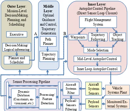
sensor processing pipeline which is responsible for real-time model estimation and sensor fusion from the onboard payload sensor using probabilistic methods. Autopilot Control Pipeline (Direct Sensor Loop Closure)
A B
Figure 9. Three-level payload directed flight controller.
The sensor processing pipeline has been tested in a few applications, including: a probabilistic occupancy grid to monitor and predict smoke plume propagation from a series of 2D visual images (Lee and Ippolito, 2009), and a magnetic anomaly map developed for unmanned ground vehicle based geophysical surveys using magnetometers (Lee, et al, 2010). A model developed for the Surprise Valley mission included two sensor processing components, with magnetometers feeding the magnetic model and the downward facing scanning radar altimeter feeding an occupancy-grid-based ground hazard model.
A middle-layer controller is responsible for trajectory generation and optimization based on the model generated by the sensor processing component. Trajectory optimization utilizes NAETGen, a real-time constrained control optimization engine for non-linear systems developed at NASA Ames Research Center in support of NASA Aeronautics (Ippolito and Yeh, 2009a; Ippolito, 2010). The inner-layer controller is responsible for controlling the vehicle at higher frequency response rates to accurately follow the trajectory specified by the middle layer controller, which requires aggressive non-linear flight control in multiple flight regimes. The inner-layer is also responsible for direct aircraft control as required for target tracking, while also minimizing perturbations within the field of view of the sensor. For hyperspectral pushbroom or other imaging applications, the unconventional prioritization of pitch and roll stabilization above the control imperative to minimize tracking error between waypoints is implemented at this level. This layer must be constrained by safe limits on all control surface manipulations to ensure that commands generated by logic in the higher levels of control cannot precipitate loss of aerodynamic stability and control. The preferred approach is to build the PDF autopilot into the line of control, but include provision for a “fail down” sequence mode that transfers control back to a certified flight control system.
This design applies Trajectory Linearization Control (TLC) developed in a collaboration between NASA and Ohio University (Adami et al., 2009) in support of the NASA Payload Directed Flight project. The TLC architecture utilizes state feedback with a reference feed-forward signal derived
from a pseudo-inverse of the aircraft dynamics, with a linear time-varying stabilizing controller in the feedback loop. This system was interfaced into the Reflection Architecture, a plug and play embedded systems architecture developed at NASA Ames Research Center (Ippolito et al, 2005).
The overarching purpose underpinning this autonomous control is to maximize the efficiency of data acquisition over the required domain while complying with all data acquisition constraints. This may require the definition of a more complex merit function (including e.g. an ephemeris model for diurnal solar angle) with optimization algorithms running in the outer layer of the controller.
5. SUMMARY AND FUTURE WORK
NASA provides the Earth science community with remote-sensing assets operating from, space, within the atmosphere, and on the ground in a sensor network providing a comprehensive view of the Earth as a system and the ability to map, monitor and study natural resources. Flight experiments conducted within NASA's Airborne Science Program have access to the Mission Tools Suite which presents scientists with the capacity to monitor progress and adapt to evolving conditions in an effort to maximize experimental productivity. Both manned and unmanned aircraft assets are fitted with onboard networking, processing, payload control, and communications modules to expedite near time access to emerging data and flight conditions. Adaptive mission technologies are increasingly employed to reduce the negative impact of uncertainties that confound pre-flight planning
We have described two specific resource mapping missions designed for the 200 kg class SIERRA UAS that are somewhat unique by virtue of complex mission requirements that invite the incorporation of unconventional sensors into flight planning and control algorithms. These missions focus on resource mapping in the coastal zone and on the mapping of subsurface geological features using magnetic field detection techniques. Flight experiments were conducted in 2012 and 2013 in the Surprise Valley of north-eastern California and over the Monterey Bay respectively. These missions were reviewed with attention to unique and demanding mission requirements, the implementation of unconventional sensors to provide the necessary information to effectively adapt these missions to mitigate intrinsic uncertainties, and the potential to include these sensor inputs into a multi-layered payload-directed flight controller architecture. A high dynamic range solar tracking sensor design is described that provides an onboard flight planner with a more direct and accurate means of controlling the solar illumination and sensor geometry that define the bi-directional reflectance distribution. Satisfying a complex set of requirements for that geometry is critical for coastal zone remote sensing, particularly for an emerging experimental design scheme which leverages multi-wavelength precision radiometer measurements to more accurately quantify water leaving radiance. Most reflectance imaging schemes, but particularly line scanner instruments are also affected by additional constraints on aircraft attitude, with corresponding ramifications to the flight control algorithm.
enables adaptive mission execution under the direction of a ground based science team. Multi layer flight controller architectures that enable flight control inputs from unconventional sensors, including primary payloads, are gaining in maturity and credibility, particularly when configured with fail safe mechanisms that can quickly revert to basic autopilot functionality in case of incipient stability divergence, or excessive air loads.
Programmatic complexities precluded direct application of automated controller designs in the resource mapping missions reported here. However, the advantages of these tools and their potential to aid the mission scientist in adapting to emerging flight conditions are evident.
ACKNOWLEDGEMENTS
The authors gratefully acknowledge the support of NASA’s Research Opportunities in Space and Earth Sciences (ROSES) Program UAS Enabled Earth Science Program, Science Innovation Fund, and Airborne Science Program for the support of the research and technology reported here.
REFERENCES
Adami, T., Zhu, J., Ishihara, A., Yeh, Y., and Ippolito, C., 2009, Six DoF Trajectory Tracking for Payload Directed Flight Using Trajectory Linearization Control, AIAA-2009-1897, AIAA Infotech@Aerospace, Seattle, Washington, Apr. 6-9, 2009.
Ambrosia, V., Wegener, S., Zajkowski, T. Sullivan, D., Buechel, S., Enomoto, F., Lobitz, B. Johan, S., Brass, J., Hinkley, E., 2011, The Ikhana unmanned airborne system (UAS) western states fire imaging missions: from concept to reality (2006–2010), Geocarto International, Vol. 26, Iss. 2,
Diaz, J., Pieri, D. Arkin, C., Gore, E., Griffin, T., Fladeland, M., Bland, G., Soto, C., Madrigal, Y., Castillo, D., Rojas, E., Achi, S., 2010. Utilization of in situ airborne MS-based instrumentation for the study of gaseous emissions at active volcanoes. International Journal of Mass Spectrometry. Volume 295, Issue 3, Pages 105–112
Fladeland, M., Sumich, M., Lobitz, B., Kolyer, R., Herlth, D., Berthold, R., ... & Bland, G. (2011). The NASA SIERRA science demonstration programme and the role of small– medium unmanned aircraft for earth science investigations.
Geocarto International, Vol. 26, Iss. 2
Dunagan, S., Berthold, R., Fladeland, M., and Pieri, D., 2007. Small UAS Technologies to Enable Earth Science Missions
Proceedings of the International Symposium on Remote Sensing
of the Environment, San Jose, Costa Rica. April 9-13, 2007.
Glen, J., Egger, A., and Ponce, D., 2008, Structures controlling geothermal circulation identified through gravity and magnetic transects, Surprise Valley, California, northwestern Great Basin: Geothermal Resources Council Transactions, v. 32, p. 279-283.
Guild L., J. Dungan, M. Edwards, P. Russell, S. Hooker, J. Myers, J. Morrow, S. Dunagan, P. Zell, R. Berthold, and C. Smith, 2011, NASA’s Coastal and Ocean Airborne Science Testbed (COAST), Proceedings 34th International Remote
Sensing of Environment, April (2011): 10-15, Sydney,
Australia.
Guild, L., S. Hooker, R. Kudela, J. Morrow, P. Russell, S. Palacios, J. Livingston, K. Negrey, J. Torres-Perez, J. Broughton, S. Dunagan, 2014, NASA COAST and OCEANIA Airborne Missions Support Ecosystem and Water Quality Research in the Coastal Zone, Abstract 2014 AGU Fall Meeting, December (2014), San Francisco, USA.
Ippolito, C., Pisanich, G. and Al-Ali, K., 2005, Component-Based Plug-And-Play Methodologies for Rapid Embedded Technology Development, AIAA-2005-7122, Infotech@ Aerospace, Arlington, VA, Sep 2005
Ippolito, C., and Yeh, Y., 2009a, A Trajectory Generation Approach for Payload Directed Flight, AIAA-2009-1351, 47th AIAA Aerospace Sciences Meeting including The New Horizons Forum and Aerospace Exposition, Orlando, Florida, Jan. 5-8, 2009.
Ippolito, C., Fladeland, M., and Yeh, Y., 2009b, Applications of Payload Directed Flight, 2009 IEEE Aerospace Conference, Big Sky, MT, March 2009.
Ippolito, C., Al-Ali, K., and Dolan, J.M., 2010, Polymorphic Control of an Autonomous Ground Vehicle over Wireless Mobile Networks, AIAA-2010-3346, AIAA Infotech@ Aerospace, 2010, Atlanta, Georgia, Apr. 20-22, 2010.
Lee, R. and Ippolito, C.. 2009, A Perception and Mapping Approach for Plume Detection in Payload Directed Flight. AIAA-2009-1898. AIAA Infotech@Aerospace Conference and AIAA Unmanned...Unlimited Conference, Seattle, Washington, Apr. 6-9, 2009
Lee, R., Yeh, Y., Ippolito, C., Spritzer, J., and Phelps, G., 2010, Payload-Directed Control of Geophysical Magnetic Surveys, AIAA-2010-3345, AIAA Infotech@Aerospace 2010, Atlanta, Georgia, Apr. 20-22, 2010.
NRC Committee on Earth Science and Applications from Space: A Community Assessment and Strategy for the Future, National Research Council. 2007. Earth Science and Applications from Space: National Imperatives for the Next
Decade and Beyond. ISBN: 0-309-66714-3, P68.
Sorenson, C. E., Forgione, J., & Barnes, C., 2011. The NASA Airborne Science Data And Telemetry System (NASDAT). In
AGU Fall Meeting Abstracts (Vol. 1, p. 1283).
Van Gilst, D. P., & Sorenson, C. E., 2011. Collection, Storage and Real-Time Transmission of Housekeeping and Instrument Data Aboard Manned NASA Airborne Science Platforms. In
AGU Fall Meeting Abstracts (Vol. 1, p. 1588).
Versteeg, R., McKay, M., Anderson, M., Johnson, R., Selfridge, B, and Bennett, J., 2007. Feasibility study for an
Autonomous UAV - Magnetometer system, Idaho National