AUTONOMOUS UNMANNED HELICOPTER SYSTEM FOR REMOTE SENSING
MISSIONS IN UNKNOWN ENVIRONMENTS
Torsten Merza
and Scott Chapmanb
a
CSIRO ICT Centre, QCAT, 1 Technology Court, Pullenvale 4069 QLD, Australia – torsten.merz@csiro.au b
CSIRO Plant Industry, QBP, 306 Carmody Road, St Lucia 4067 QLD, Australia – scott.chapman@csiro.au
KEY WORDS: Unmanned Aircraft Systems, Vegetation Monitoring, Infrastructure Inspection, Automation, Platforms, Robotics
ABSTRACT:
This paper presents the design of an autonomous unmanned helicopter system for low-altitude remote sensing. The proposed concepts and methods are generic and not limited to a specific helicopter. The development was driven by the need for a dependable, modular, and affordable system with sufficient payload capacity suitable for both research and real-world deployment. The helicopter can be safely operated without a backup pilot in a contained area beyond visual range. This enables data collection in inaccessible or dangerous areas. Thanks to its terrain following and obstacle avoidance capability, the system does not require a priori information about terrain elevation and obstacles. Missions are specified in state diagrams and flight plans. We present performance characteristics of our system and show results of its deployment in real-world scenarios. We have successfully completed several dozen infrastructure inspection missions and crop monitoring missions facilitating plant phenomics studies.
1 INTRODUCTION
There is a growing interest in deploying unmanned aircraft for vegetation monitoring, photogrammetric survey, and infrastruc-ture inspection (Berni et al., 2009, Eisenbeiss et al., 2005, Mon-tambault et al., 2010). These applications are remote sensing tasks as quantitative or qualitative information about an object is acquired without making physical contact with the object. Un-manned aircraft are attractive for data acquisition because they enable sensing with high spatial and spectral resolution any time weather permits for relatively low cost. High spatial resolution can be achieved even with low-resolution sensors by capturing data close to objects of interest. The feasibility of using small un-manned aircraft for low-altitude remote sensing has been demon-strated (Nebiker et al., 2008, Berni et al., 2009), though chal-lenges remain in widespread adoption (Hardin and Jensen, 2011). This paper focuses on the automation of the data acquisition part of a low-altitude remote sensing task.
Helicopters are well-suited for quasi-static positioning of sensors in 3D space and moving sensors along 3D paths with high preci-sion. Even in windy conditions, helicopters enable precise flight control and operations in cluttered environments because of their maneuverability and ability to fly at any low speed. Precise and repeatable collection of sensor data is achieved through automatic flight control. From an operational point of view, helicopters only require a small area for takeoff and landing and are rela-tively easy to transport thanks to their compact size. Flying un-manned helicopters, however, requires a skilled pilot, especially for flights at greater distances and close to obstacles. Within visual range (VR), flights are usually conducted as RC (radio-controlled) flights. Manual flights Beyond Visual Range (BVR) are possible in First Person View (FPV) mode with video goggles but situational awareness is challenging and it requires a reliable communication link. From a safety point of view, helicopters are also problematic. Larger helicopters especially can cause signifi-cant damage when they fail. On the other hand, larger platforms are often required for carrying heavy and bulky sensor packages or for covering large areas.
We aim to overcome the problems of deploying unmanned he-licopters for remote sensing applications by developing depend-able autonomous helicopter systems which do not require expert
Vertical camera mount
LIDAR Inspection camera
GNC system
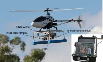
Figure 1: The CSIRO autonomous helicopter system.
users. Given there is no interaction required for specifying a task during flight, truly autonomous helicopters also do not re-quire communication links. For BVR flights at low altitude in unknown environments, i.e. without a priori information about terrain elevation and obstacles, the following three capabilities are essential for an autonomous helicopter: (1) ground detection and terrain following; (2) obstacle detection and avoidance; and (3) stable, effective control. Autonomous flights with unmanned helicopters close to ground and obstacles have been successfully demonstrated by (Scherer et al., 2008) and (Tsenkov et al., 2008). However, it is unclear if the helicopters can safely be operated be-yond visual range without a backup pilot. Moreover, the proposed methods are computationally expensive and have been demon-strated with heavy, high-end components. One of our objectives has been to maximize application payload capacity. We devel-oped computational efficient methods for flights in unknown en-vironments which only require a lightweight COTS 2D LIDAR and no separate on-board computer. A detailed description of the methods can be found in (Merz and Kendoul, 2011).
that can justifiably be trusted) as described in (Avizienis et al., 2000). Dependability has the following attributes: availability, reliability, safety, confidentiality, integrity, and maintainability. In our design, we have considered all of the attributes above.
There are several means to attain dependability: fault prevention, fault tolerance, fault removal, and fault forecasting. There is little literature on the design of dependable autonomous unmanned he-licopter systems. Most research related to dependability of such systems focuses on achieving reliability through fault tolerance. Methods for fault tolerant flight control and guidance systems can be found in (Ducard, 2009). Implementing fault tolerance requires additional computational power (e.g. diverse implemen-tations of filters and controllers) or additional hardware (e.g. re-dundant actuators or flight computers) which effectively reduces payload capacity. On the other hand, fault prevention, removal and forecasting alone reduces the risk of failures significantly. We focus on failures which are likely to occur and which have catastrophic consequences. For attaining dependability we put significant effort in the design, selection, manufacturing, testing, and maintenance of critical components. We attain fault tolerance through system monitors (error detection) which invoke system reconfigurations or control mode changes (system recovery).
In the following section, we present a decomposition of a proven autonomous helicopter system with a description of its compo-nents. Thereafter, we propose flight services which are useful for remote sensing applications. Flight services are based on the de-scribed components. Section 3 presents performance characteris-tics of our helicopter system and shows results of its deployment for real-world remote sensing missions.
2 SYSTEM COMPONENTS AND FLIGHT SERVICES
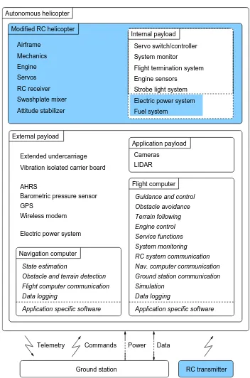
Larger autonomous helicopters are complex systems. To tackle the problem of complexity we decompose a system in hardware and software components which can be individually tested against a specification (Figure 2). For modelling system behavior and seamless integration of software components considering real-time constraints we use the ESM software framework (Merz et al., 2006). To minimize risks, critical components have to pass ground tests before they are flight tested and all glitches observed on the ground and during flight are thoroughly analyzed.
The unmanned aircraft system (UAS) we propose consists of an autonomous helicopter and a portable ground station (Figure 1). Communication with the helicopter is realized through a spread spectrum wireless modem with encryption. The ground station offers a convenient user interface to the aerial robot. It reduces risks of failures during BVR operations and simplifies flight test-ing. However, it is not an essential component for operating the helicopter. The RC transmitter is used for manual flights. In BVR mode it is switched off.
The ground station has a touchscreen with a user configurable graphical layout and a backup user interface including a flight termination switch. The touchscreen is used for (1) selecting flight plans; (2) starting and aborting mission plan execution; and (3) monitoring and setting of on-board system parameters. The backup interface permits to send commands to the helicopter in case of a failure of the graphical interface. The ground station stores flight plans, records data received from the helicopter dur-ing flight, and archives flight data after landdur-ing. Flight plans are uploaded to the flight computer through the wireless data link. For wireless communication, we use a packet based transmission method with constant transmission rate, fixed packet size, and minimal data buffering to avoid latencies.
AHRS
Figure 2: Components of the helicopter system. Components of a typical COTS RC helicopter are printed on blue background. Software components are printed in italics.
The autonomous helicopter is based on a COTS RC helicopter (Vario Benzin Trainer). The main criteria for choosing the RC he-licopter have been: (1) proven reliability with a specified payload capacity of at least 5kg; (2) easy handling; and (3) quick availabil-ity of spare parts. Modifications to the helicopter have been held to a minimum to avoid compromising its proven reliability. The available payload capacity is divided into internal and external payload. The internal payload includes all application indepen-dent components added to an RC helicopter which are integrated with the base airframe. The external payload consists of an ex-tended undercarriage and a vibration isolated carrier board hold-ing the remainhold-ing components. The extended undercarriage is at-tached to the original undercarriage of the RC helicopter. Without the external payload the helicopter is a fully functional RC heli-copter. The GNC (Guidance, Navigation, and Control) system required for autonomous flight and mission specific components are part of the external payload. We have several modified RC he-licopters of the same type and several different external payloads which can be attached to any of the helicopters. Table 1 contains technical specifications of the key components of our helicopter system.
The main internal components we add to a COTS RC helicopter are an interface to the RC components (receiver, swashplate mixer, attitude stabilizer, servos), a system monitor, an electrical power system, and a flight termination system. In addition, we replaced the original fuel tank with a larger tank and integrated sensors for fuel level, engine temperature, and engine RPM. The system monitor monitors, among others, fuel level, voltages, engine tem-perature, RC link, and a signal from the flight computer indicating its correct operation (heartbeat). A strobe light indicates critical problems such as loss of RC link by flashing with high frequency and warnings such as low fuel or low battery by flashing with low frequency.
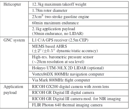
termina-Helicopter 12.3kg maximum takeoff weight 1.78m rotor diameter 23cm3
two-stroke gasoline engine 60min maximum endurance 2.1kg application payload (30min endurance, no LIDAR) GNC system L1 C/A GPS receiver (2.5m CEP)
MEMS based AHRS (±2◦/±0
.5
◦dynamic/static accuracy)
High-res. barometric pressure sensor (∼20cm resolution at sea level)
Hokuyo UTM-30LX 2D LIDAR (optional) Vortex86DX 800MHz navigation computer Via Mark 800MHz flight computer Application RICOH GX200 digital camera with zoom lens payload RICOH GR Digital III digital camera
RICOH GR Digital III camera mod. for NIR imaging FLIR Photon 640 thermal imaging camera
Table 1: Technical specifications of key system components.
tion system kills the engine and commands full collective pitch in case of RC link loss, low voltage, or miscellaneous fatal er-rors. For BVR flights, a loss of the RC link is ignored as long as the heartbeat signal is active. The flight termination is activated when the heartbeat is inactive and the RC link is lost or in case of low voltage or fatal errors. In addition, it can be activated by the flight computer.
The on-board electrical power system is designed for a wide range of supply voltages. During flight, a single LiPo battery powers the RC components and the GNC system. On the ground the he-licopter is powered externally. Having to replace only one battery enables quick turn around times. The power system also includes a low self-discharge backup battery for supplying the RC compo-nents in case of a power failure.
2.1 GNC System
The GNC system consists of a navigation computer, a flight com-puter, and the following sensors: an Attitude and Heading Ref-erence System (AHRS), a GPS receiver, a barometric pressure sensor, and optionally a 2D LIDAR for obstacle detection. The LIDAR has a 270◦scan range and is mounted vertically pointing
forward, i.e. the scanning plane is parallel to the yaw axis and the center beam parallel to the longitudinal axis of the helicopter. All components are part of the external payload and mounted to the same vibration isolated carrier board. The GPS antenna is placed on the tail boom. The pressure sensor is mounted under-neath the carrier board in a box with openings away from strong air flow. Although the AHRS is surrounded by ferrous objects and electronic components the magnetometer could be calibrated for accurate heading estimates. The greatest disturbance is the engine. Calibration was performed with running engine.
Computation is split across two computers because of limited computing power and for modularity. The navigation part is im-plemented on the navigation computer, the guidance and control part on the flight computer. Control inputs are sent to the RC system through a serial link. The execution of different software components and their data flow is managed by two coupled, de-terministic state machines, one for each computer. Both state machines are implemented in ESM. Functions are implemented in C. All computers run Linux with a real-time kernel patch and the ESM run-time environment.
The system includes a simulator component enabling hardware in the loop (HIL) simulations in real-time. HIL simulation is a valuable tool for testing the interaction of system components.
Another ground test applicable to portable helicopters is running the control system in the hovering state, moving the helicopter, and observing the servos. Both computers contain a solid state drive based data logger. The data loggers record sensor data and control inputs at a high rate and all important state transitions. This allows for accurate analysis of flights during development and in case of problems. Flight and state machine data is also sent through the telemetry link to the ground where the data is visualized and recorded.
The navigation computer calculates helicopter state estimates us-ing extended Kalman filters and processes LIDAR range data to estimate height above ground and distance to frontal obstacles. The data is sent to the flight computer at a high rate. Flight control is based on cascaded, decoupled SISO PID controllers for attitude angles, velocities, and positions using state estimates. The flight computer also includes a PI controller combined with a feedforward controller using collective pitch input for maintain-ing constant main rotor speed. In our experience, properly tuned PID controllers suffice for controlling unmanned helicopters for remote sensing applications. The basic flight modes are hover, yaw, climb, descent, and cruise. During forward flight the heli-copter controls its height either based on barometric pressure or height above ground which is estimated from LIDAR readings. The latter results in a terrain following behavior. The helicopter follows a vertical or horizontal straight line path during climb, descent, and cruise.
We added two special flight modes –pirouette descentand wag-gle cruise– which increase the field of view of the 2D LIDAR. The pirouette descent mode enables descents in unknown envi-ronments without colliding with obstacles or terrain. It creates a spinning LIDAR with a cylindrical field of view by rotating the helicopter around its yaw axis while descending vertically. During a climb, the helicopter does not perform pirouettes as we assume there are no obstacles above the helicopter. The wag-gle cruise mode is used to detect obstacles during horizontal path following. It performs a horizontal sweep while flying forward, allowing to scan a corridor-shaped space.
2.2 Application Payload
The helicopter can carry a combination of a variety of sensors typically used for remote sensing. All sensors are mounted to the same vibration isolated carrier board which also holds the GNC system. This has two advantages: there is no need for ad-ditional vibration isolation and it is possible to use the helicopter state estimates for determining the pose of a sensor. Sensors can be mounted in any orientation. Sensors for vegetation monitor-ing are typically mounted vertically pointmonitor-ing down, sensors for structure inspections are typically mounted horizontally pointing forward. The undercarriage can be further extended to accommo-date larger sensors.
The digital cameras support raw image capture and manual expo-sure and focus control. The time it takes from sending a shutter command from the flight computer until a camera captures an image has been calibrated.
2.3 Flight Services
We developed systems for delivering the following flight services: (1) take off; (2) hover; (3) heading change; (4) waypoint flight; (5) waypoint flight with obstacle avoidance; (6) waypoint flight with air traffic control interaction; (7) return to base; (8) close-range inspection; and (9) landing assistance. Note that a service delivered by a system is its perceived behavior which may dif-fer from its intended function (Avizienis et al., 2000). The term ’flight service’ refers to a description of an intended function of the helicopter system.
In the following, we provide a brief description of flight services useful for remote sensing applications. Before requesting a flight service except for service (1), the helicopter must hover. After delivery of a correct flight service, the helicopter will hover. The take offservice includes warming up the engine and spooling up the rotor. When ready for take off, the helicopter performs a ver-tical climb to a height well outside the ground effect zone. The climb finishes in hover. Thehoverservice is based on the hover mode (Section 2.1). Theheading changeservice is used for point-ing the helicopter in a specified direction durpoint-ing hover. Position changes are achieved through three differentwaypoint flight ser-vices: Service (4) is used for flights in obstacle free space. While flying to a given waypoint, the helicopter accurately tracks verti-cal and horizontal straight line paths. Service (5) enables opera-tions in airspace shared with other aircraft. To ensure separation between the helicopter and other aircraft, the helicopter interacts with theAutomated Dynamic Airspace Controller(ADAC) sys-tem developed byBoeing Research and Technology USA (Cloth-ier et al., 2011). Service (6) allows to fly safely to a specified des-tination in areas likely to contain obstacles. The implemented LI-DAR based avoidance strategy does not require maps and despite being reactive, guides the helicopter in most cases to the specified destination. Thereturn to baseservice is utilized to fly the heli-copter on the shortest path to a pre-defined location in obstacle free space avoiding pre-defined no-fly-zones. Theclose-range inspectionservice enables positioning the helicopter at a speci-fied height at a given distance from a structure. The helicopter approaches the structure defined by geographic coordinates from a given approach point until the distance measured by the LIDAR reaches the specified distance. Flight service (9) is requested to assist the user in landing the helicopter. The user only commands vertical velocity. Landing has not been fully automated yet as the helicopter currently can not reliably estimate distance to a given touch down point and horizontal velocity before touch down.
For flight services (2–5) and (8) the user can choose between pressure based height control or terrain following for low-altitude flights. Services with position or direction changes include ac-celeration and deac-celeration stages accounting for dynamical con-straints of the helicopter. A requested service will be rejected or a provided service cancelled if given parameters or circumstances do not allow a safe flight. In addition to the flight services, there is a helicopter shutdown service which is available when the air-craft is on the ground.
Missions are specified in ESM state diagrams and flight plans. ESM state diagrams are converted in state machine code with tools of the ESM framework. State machines request flight ser-vices and other serser-vices based on events from timers, serser-vices, and system monitors. A flight plan is a sequence of 3D waypoints
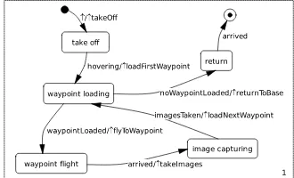
Figure 3: Example of an ESM state diagram defining a simple mission plan.
with cruise speeds and optional parameters (e.g. for terrain fol-lowing). Flight plans are uploaded from the ground station to the helicopter either before take off or while hovering. Mission plans defined in ESM are part of a complex state machine. However, thanks to the decomposition properties of ESM, the user does not have to understand details of subsystems to model behaviors. The state diagram shown in Figure 3 models a simple remote sensing mission where the helicopter is commanded to take off, fly to waypoints defined in a flight plan, take images at each waypoint, and return to base. Mission and flight plans can be generated manually or by a mission planner.
3 SYSTEM PERFORMANCE AND DEPLOYMENT
In this section, we first present performance characteristics of our helicopter system. All flights have been conducted in accordance with the Australian civil aviation safety regulations. Our system is typically operational within 15 minutes after arriving at a take off location.
Flights Hours Locations Mishapsa
VR auto ∼400 ∼100 10 0
BVR 18 9.8 2 1
Manual 938 168 11 5
a
with damage to the helicopter affecting its suitability for safe flight
Table 2: Flight statistics of four helicopters.
Table 2 shows data from the log books of the four helicopters we have been using. There were very few flights with damage to the aircraft which demonstrates the dependability of the sys-tem. Two helicopters were damaged beyond repair. The first helicopter crashed during a BVR flight and the second during a manual flight.
Table 3 lists the empirical error bounds for different basic flight modes. The errors bounds are estimated from recorded flight data of several flights in winds up to 10m/s from different directions by comparing desired values with state estimates. Velocities are with respect to the earth fixed frame. The horizontal position error of the cruise mode refers to the error when reaching a way-point. The listed control errors do not include state estimation errors and we assume that state estimation errors do not signif-icantly affect control errors. As our focus has been on depend-ability rather than control performance, there is certainly room for improvement; especially for flights at higher airspeed and in turbulent conditions. For our applications, though, the achieved control accuracy has been sufficient. In calm conditions, the pitch angle of the carrier board is less than 2◦at 3m/s forward speed.
hover 5m/s cruise 1m/s climb/desc. yaw
h95[m] 0.8 1.1 1.0
r95[m] 1.8 3.0 2.4 2.9
c95[m] 1.6
ψ95[◦] 9 8
v95[m/s] 0.9 0.3
a
95 percentile of absolute error
h=height error,r=horizontal position error,c=cross track error, ψ=heading error,v=horizontal/vertical velocity error
Table 3: Empirical control error boundsaof basic flight modes.
Height Height AGL Terrain height Reference [m]
[s]
Figure 4: Helicopter height during a terrain following flight.
10m Waypoint 2
Original flight path Waypoint 1
Detection of obstacle
Detected obstacle points Generated avoidance waypoints
Figure 5: LIDAR based obstacle avoidance.
to 2m/s. The terrain following began after a descent during which height control was changed from pressure based control to LI-DAR based control. Figure 5 shows a typical obstacle avoidance scenario. During a mission, the state machine requested the goal-oriented obstacle avoidance service described in Section 2.3 for a flight from waypoint 1 to waypoint 2 with 1m/s. The system successfully detected the tree and ’tracked’ its outline at a safe distance until it intersected with the original flight path.
3.1 Infrastructure Inspection
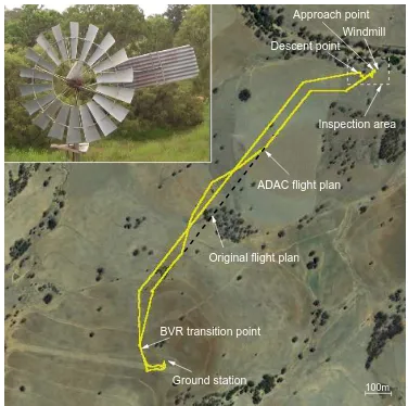
The helicopter system provides infrastructure inspection services by combining the flight services presented in Section 2.3. We have successfully completed 37 inspection missions with frontal and vertical image capture and recorded more than 14 hours of autonomous flight time. All flights were performed without pro-viding a priori information about the environment and two mis-sions were flown in BVR mode without a backup pilot. At the end of the Smart Skies project (Clothier et al., 2011), we demon-strated the execution of a BVR inspection task with air traffic con-trol interaction. The task included a 1.4km flight to an inspection area, the inspection of a windmill, and the return to base. Before take off, a flight plan was uploaded defining a descent point in the inspection area, the approach point, and the position of the windmill. During the flight to and from the inspection area, the helicopter interacted with the air traffic control system mentioned in Section 2.3 to ensure separation from other aircraft. The cruise speed was set to 5m/s. Results of one of the inspection missions
ADAC flight plan
BVR transition point
Ground station
Inspection area Windmill Descent point
Original flight plan
100m Approach point
Figure 6: Helicopter trajectory of a BVR windmill inspection mission and zoomed inspection image taken by the helicopter.
are shown in Figure 6. The helicopter hovered approximately 10m in front of the windmill to take images. The inspection im-age shows sufficient detail for analysis. During the return flight, the air traffic control system sent a flight plan to the helicopter to avoid an oncoming aircraft. A detailed description of the mission can be found in (Merz and Kendoul, 2011).
3.2 Plant Phenomics
Plant phenomics is the application of new technologies to the measurement of plant phenotype, i.e. the physical characteristics of plants, particularly when grown in mono-cultures as a crop. The meaning of ’phenomics’ derives from the word ’genomics’ which was coined during the 1990s to describe the study of the genetic composition of a species which was being revealed by new DNA detection and measurement technologies. Hence, high-throughput image analysis of crop growth is considered to be a ’phenomics’ technology. Previous research has demonstrated the value of UAS-gathered imagery to interpret spectral reflectance characteristics of crops and trees at spatial resolutions of ca. 20 cm (Berni et al., 2009) and to consequently monitor contrasting irrigation treatments, for example. Applications in plant phe-nomics aim to compare the growth and development of different plant varieties or cultivars, and the causes of such genetic dif-ferences tend to be more subtle than those between agronomic treatments.
To resolve individual leaves of wheat (1 to 2cm) using the digi-tal cameras listed in Table 1, missions have been flown at 15 to 30m, cf. the 150m of Berni et al. The flights were scheduled to cover entire fields of approximately 1 to 1.5ha in size (Figure 7) and obtained measurements across multiple experiments planted within each field. Typically, the flights were flown at two eleva-tions: at 30m to obtain high-density, high-resolution images, and at 60m to capture entire experiments in single images. We have successfully completed 40 missions and recorded more than 16 hours of autonomous flight.
50m
Autonomous flight
Ground station First waypoint
Last waypoint
landing and Take off Manual flight
[m]
[s] Autonomous flight
Manual flight Height
Reference
Figure 7: Flight path and height of a typical plant phenomics mission.
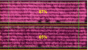
65% 87%
Figure 8: Differences in leaf area ’cover’ of two plots of wheat estimated from processed NIR images acquired by the helicopter.
the relative leaf temperature (using a thermal sensor). These types of images are being used as part of a project to identify wheat varieties with improved adaptation to higher temperature condi-tions as may be experienced if expected changes in climate come about.
4 CONCLUSIONS
We presented the design of an unmanned helicopter system ca-pable of performing remote sensing missions in unknown envi-ronments autonomously beyond visual range. Missions are spec-ified in state diagrams and flight plans. This approach is flex-ible and enables definition of complex missions. Our focus has been on system dependability which is a key requirement for real-world deployment. We use a component based approach to tackle the problem of complexity of such a system. The concepts and methods we propose are applicable to any larger unmanned heli-copter. The design has been validated through the development and deployment of the CSIRO autonomous helicopter. The he-licopter has been successfully deployed for autonomous captur-ing of images for infrastructure inspections and plant phenomics studies. We have not encountered problems with motion blur and the recorded images show objects of interest with sufficient detail. To decide if a system is suitable for a particular remote sensing task, we estimate the accuracy at which sensors can be positioned in 3D space as well as the accuracy of pose estimates during im-age capture.
Future work is directed towards further increase of dependabil-ity and the level of autonomy by including failure modes dealing with GPS problems, an autonomous landing service, and a mis-sion planner.
ACKNOWLEDGEMENTS
The authors would like to thank the CSIRO UAS team members for their contributions during the development of the helicopter system and Amy Chan for assistance with processing of wheat images. Funding was provided by the Queensland State Govern-ment Smart State Funding Scheme; the CSIRO Climate Adapta-tion Flagship; the Climate Change Research program of the De-partment of Agriculture, Fisheries and Forestry, Australian Gov-ernment (GMS-0335 A national research program for Climate-Ready Cereals) and the Australian Grains Research and Devel-opment Corporation (GRDC-CSP00136).
REFERENCES
Avizienis, A., Laprie, J. and Randell, B., 2000. Fundamental con-cepts of dependability. In: Proceedings of the Third Information Survivability Workshop, ISW-2000, Boston, USA.
Berni, J., Zarco-Tejada, P., Su´arez, L. and Fereres, E., 2009. Thermal and narrowband multispectral remote sensing for vege-tation monitoring from an unmanned aerial vehicle. IEEE Trans-actions on Geoscience and Remote Sensing 47(3), pp. 722–738.
Clothier, R., Baumeister, R., Br¨unig, M., Duggan, A. and Wil-son, M., 2011. The Smart Skies project. IEEE Aerospace and Electronic Systems Magazine 26(6), pp. 14–23.
Ducard, G., 2009. Fault-tolerant Flight Control and Guidance Systems. Springer.
Eisenbeiss, H., Lambers, K. and Sauerbier, M., 2005. Photogram-metric recording of the archaeological site of Pinchango Alto (Peru) using a mini helicopter. In: Proceedings of the 33rd CAA Conference, Tomar, Portugal.
Hardin, P. and Jensen, R., 2011. Small-scale unmanned aerial vehicles in environmental remote sensing: Challenges and op-portunities. GIScience & Remote Sensing 48(1), pp. 99–111.
Merz, T. and Kendoul, F., 2011. Beyond visual range obstacle avoidance and infrastructure inspection by an autonomous he-licopter. In: IEEE/RSJ International Conference on Intelligent Robots and Systems, IROS 2011, San Francisco, USA.
Merz, T., Rudol, P. and Wzorek, M., 2006. Control system frame-work for autonomous robots based on extended state machines. In: International Conference on Autonomic and Autonomous Systems, ICAS’06, Silicon Valley, USA.
Montambault, S., Beaudry, J., Toussaint, K. and Pouliot, N., 2010. On the application of VTOL UAVs to the inspection of power utility assets. In: Applied Robotics for the Power In-dustry (CARPI), 2010 1st International Conference on, Montreal, Canada.
Nebiker, S., Annen, A., Scherrer, M. and Oesch, D., 2008. A light-weight multispectral sensor for micro UAV – opportunities for very high resolution airborne remote sensing. International Archives of the Photogrammetry, Remote Sensing and Spatial In-formation Sciences XXXVII Part B1.
Scherer, S., S.Singh, Chamberlain, L. and Elgersma, M., 2008. Flying fast and low among obstacles: Methodology and ex-periments. International Journal of Robotics Research 27(5), pp. 549–574.