AUTONOMOUS AIRSHIP EQUIPPED BY MULTI-SENSOR MAPPING PLATFORM
Jakub Jon a, Bronislav Koska b, Ji
ří Pospíšil c
Department of Special Geodesy, Faculty of Civil Engineering, Czech Technical University in Prague a
[email protected], b [email protected], c [email protected]
KEY WORDS: Airship, Mapping, Direct Georeferencing, Thermometry, UAV, Laser scanning
ABSTRACT:
The aim of the project is to create measuring system with specific properties suitable for effective mapping of medium-wide areas (units to tens of square kilometers). The system should be useful especially for ranges that are too large for conventional surveying with GNSS or total station and too small for use of manned air vehicles from economical and accuracy point of view. Accessories of the system will allow e.g. collecting data for urban area modeling, creating thermometric georeferenced maps, mapping of dangerous or inaccessible areas (damps, open-pit mines). For this reason the platform is equipped with laser scanner, VIS camera (one for vertical capturing or more for slope capturing), thermo camera and INS/GPS as an exterior orientation (pose) determination unit. Especially in task of urban modeling the airship, as carrier, have legislative advantages due to prepared restriction for UAV. The resulting absolute accuracy of the developed system should be better than 10 cm (position standard deviation) and the random component is less than 5 cm. This accuracy is lower than for conventional measurements, but significantly higher than the scanning system carried by piloted aircraft. In terms of properties (accuracy, speed of data collection) our system is close to the terrestrial mobile scanning systems, which has disadvantage in the lack of availability in hard to reach locations.
1. INTRODUCTION
This article describes the process of set up of all components of UAV airship with multi-sensor platform to get entire system operational. Second paragraph is describing financing of the project, time schedule and participants. Third paragraph introduces airship and its attributes. Fourth paragraph gives an overview about used equipment with its parameters.
Data from each instrument complement each other in process of creation of final output therefore space relation and time synchronization of all instruments needs to be known precisely. Paragraphs five and six deal with these issues.
2. PROJECT DESCRIPTOIN
2.1 Financial support
Whole project is supported by Technology Agency of the Czech Republic from the program "Technology and System for Physical and Spatial Characteristics Determination for Protection and Formation of Environment and for Increasing of Energy Sources Potential".
2.2 Time schedule
In the summer of 2011 the instruments were purchased and the production of airships was ordered. During 2012 the platform assembly, the first calibration procedures and time synchronization was conducted. In mid-2013, we expect, the system is functional for the final tests and the first practical use can be realized.
2.3 Participants
The principal investigator is the Czech Technical University in Prague represented by the Faculty of Civil Engineering and the Faculty of Mechanical Engineering. There are two more participants, Control System International Inc. that performs
surveying activities and specializes in static and mobile laser scanning, and company ENKI, o.p.s., which has long experience in aviation thermometric mapping and environmental studies.
3. AIRSHIP
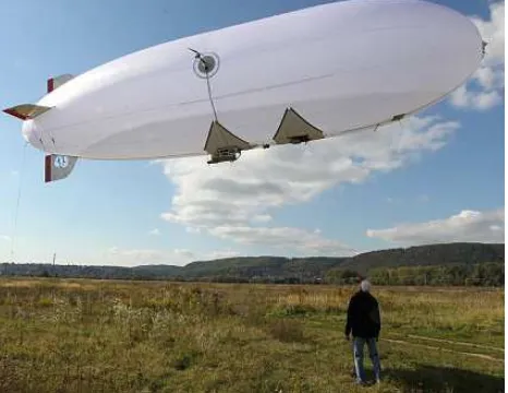
The selection of carrier was based on our specific requirements such as carrying capacity in the first place, long flight time, safety (in case of failure there is no danger of straight fall, airship staying heavier than air therefore it will drop smoothly to the ground without jeopardy of people’s health or equipment) and flight characteristics such as stability of flight in terms of vibrations and possibility to flight at low speed.
Figure 1. UAV airship ACC15X
The airship ACC15X made by airshipclub.com is 12m long with maximum oven’s diameter 2,8 m filled with helium of volume 57 m3. Operating speed 30 km/h and maximal 55 km/h
with high-rise accessibility 1000 m. Movement is provided mainly by two side electro motors with propellers. Whole system is powered by an engine generator that can work about 3 hours.
4. EQUIPMENT
Currently, complete equipment consists of INS / GPS navigation unit (iMAR iTracer – F200), laser scanner (SICK LD-LRS1000) with conical modification, digital camera in the visible spectrum (Olympus E-PM1) and thermometric professional camera (FLIR SC645). For logging data is used industrial computer Stealth LPC-125LPM. All components are mounted on one platform close to each other to prevent inaccuracies due to torsion of construction.
4.1 Measuring platform
Measuring platform is designed and optimized especially to run hanged on airship. It is mounted in the muted double gravitational gimbals and it has modular concept which allows employing different sensors and changes its amount and position. The only limitation is total weight, which shouldn’t exceed 15 kg (carrying capacity of airship).
Cardan hanging was chosen for stabilizing of the platform during a flight operations and due to the fact that it protects against unbalanced and “shaky” instrument field of view.
4.2 INS / GPS navigation unit
iMAR iTracerRT-F200
• intended for direct georeferencing • fiber optic gyroscope
• MEMS accelerometers
• accuracy according manufacturer
o ± 2 cm + 2 ppm (INS/RTK-GPS) o ± 10 cm (10 s GPS outage) o 0.01°(roll, pitch), 0.04°(heading) • fervency 200 Hz
• weight 2.4 Kg
Figure 2. iMAR iTracerRT-F200
4.3 Digital camera
Olympus PEN E-PM1
• body
o 4/3" MOS sensor 4032 x 3024 o 17.3 x 13.0 mm
• lens
o Olympus M.Zuiko 12mm f/2
Figure 3. Olympus PEN E-PM1 and M.Zuiko 12mm f/2
4.4 Thermometric camera
Professional thermometric camera Flir SC645 was acquired. Its most important parameters are stated in Tab. 1 for details see (FLIR).
Resolution [pixel] 640 x 480
Wavelength [micron] 7.5-13
Pixels spacing [micron] 17
Scanning frequency [Hz] 25
Accuracy 2 ° C or 2% of the value
Table 1. Flir SC645 parameters
Figure 4. Thermometric camera Flir SC645
4.5 Laser scanner
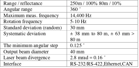
Scanner Sick LD LRS1000 is a rotational 2D scanner intended primarily for use in industrial and safety applications. With progress in the development of autonomous vehicles and mapping systems it is, thanks to a long tradition of manufacturing and good price-performance ratio, often deployed as a mapping sensor. The most important parameters of scanner are stated in Tab. 2 for details see (SICK).
Range / reflectance 250m / 100% 80m / 10%
Angular range 360 ˚
Maximum meas. frequency 14,400 Hz
Rotation frequency 5-10 Hz
Standard deviation (random) 30 mm
Systematic deviation ± 38 mm to 80 m, ± 63 mm > 80 m
The minimum angular step 0.125 ˚
Output beam diameter 40 mm
Laser beam divergence 2.8 mrad = 0.16 ˚
Interface RS-232/RS-422,Ethernet,CAN
Table 2. Sick LD LRS1000 parameters
Figure 5. Sick LD LRS10001
Due to planned usage in airborne mapping, a unique conical modification is being developed. Conventional linear laser scanner is modified into a form of conical laser scanner. In case that laser scanner stays linear, 60% of plain in which we measure points will stay unused. By turning plain into cone, we could use every laser beam direction to calculate the coordinates on surface. The other advantage of this modification is that with one sensor we could scan backward and forwards together at the same time. This modification will cause the reduction of shadow zones in the point cloud in rugged environments.
5. SPATIAL RELATIONSHIPS DETERMINING
5.1 Determination of parameters for conical laser scanner modification
For the purpose of the project was linear laser scanner supplemented by the mirror which serves for focusing laser beam at distance of 80m and to deflect the beam by 30°. Technical scheme of this modification is shown in the following figure.
Figure 6. a) Scheme of modification (left) b) scanner coordinate system (right)
On the Figure 2. a) are (2) rotary scanners head (1) collar for mounting, (3) shoulder carrying the focusing mirror, (4) symmetrically placed arm serving for the dynamic balance.
All calculations are realized in coordinate system of the scanner (Figure 2. b)) which is fixed to a scanner body, origin is placed on rotational axis in place where laser beam is deflected towards focusing mirror. The Z-axis direct upwards in direction of
the direct distance between the origin of the coordinate system of the scanner and the point of impact of the laser beam on the mirror. Advantage of c0 is the possibility of its precise
determination in laboratory. Between parameter of the plane cm and parameter c0 is possible to derive a relationship:
0 surface with coordinates X (x, y, z).
After connection of all relationships we could get equation describing mathematical model of our modified scanner (relationship between point on surface, unknowns and measured values):
To solve this equation we need to specify additional conditions such as information about scanned surface (condition for relationships between measured points). For example, one set of point belongs to the same plane or two sets of points belong to two different plains, which are perpendicular.
Figure 7. Practical test – scanner mounted on tripod
Measurements were performed using the library Sick LIDAR Matlab / C + + Toolbox, see (Derenick).
During practical test, scanner was mounted on tripod and was directed towards wall corner. Set of measurements was acquired, each of them with little different position. Each set contains ten subsets of distances in angular step of 0.25°. Subsets were averaged in to one to reduce noise.
Model of adjustment is based on the method of least squares. Specifically, the sum of squares of distances from the plane to each point is minimized, where the coordinates of points are expressed by equation (2).
Measurements are angular positions of scanner head and lengths to points. Unknowns are three parameters of mirror plane nmx,
nmy, nmz and (c0 is measure directly), and the parameters of
individual oriented planes (four for each plane).
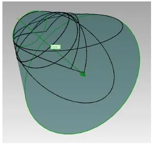
Figure 8. Final cone with points in planes
In the realized experiment four planar scans and two scans lying in two perpendicular planes were used. Each scan contained 1440 distances. A posterior unit standard deviation of adjustment is 0.0034 m in our case represents the root mean square of the distances from the points to the targeted planes.
Parameter Value [m] Std. [m]
nmx -0.861307 0.000046
nmy -0.00232 0.00060
nmz 0.508077 0.000079
Table 3. Resulted values of mirror normal vector
Standard deviation represents at distance of 100 meters deviation in x-axis 0.0091 m, y-axis 0.060 m and in z-axis direction 0.0092 m. Achieved deviation for nmx and nmz is
sufficient. It would be appropriate to propose a different measurement configuration for nmy, which would reduce the
uncertainty in the parameter. Appropriate solution should be to measure corner of a room (triplet of orthogonal planes).
5.2 Determination of external orientation parameters for digital camera
It is necessary to estimate spatial relationship between INS/GPS and digital camera for direct georeferencing of digital images. For this purpose we tested straight indirect determination of angular differences and origin off-sets of coordination system of INS/GPS and camera.
The method is based on comparison of the navigation data from the INS / GPS in specified time intervals (1 second) with calculation of external orientation parameters of the camera in the same intervals. External parameters are obtained after following steps.
Approximate relative position and orientation of cameras are obtained by structure-from-motion processing of images of calibration field, consisting of sixteen photogrammetric targets of known location, during dynamic movement (all components were mounted on a carriage).
Resulting relative position of cameras is transformed, using targets as ground control points and Helmert transformation, to the global coordinate system.
Furthermore, the positions and orientations of cameras are precised by spatial intersection from the directions back to the targets. It is necessary to calibrate internal camera parameters for back resection and to obtain image coordinates of the targets.
Figure 9. Calibration field with detail of target
Parameter Mean [°] Std. [°]
roll difference 2.08 0.18
pitch difference 6.48 0.06
yaw difference 139.01 0.14
Table 4. Angular differences between camera and INS/GPS
Parameter Mean [m] Std. [m]
x 0.32 0.06
y 0.07 0.04
z 0.22 0.08
length of vector 0.41 0.06
Table 5. Coordinate differences between camera and INS/GPS
From the results of the tests we deduced that this method is not suitable for coordinate differences determination, which must be directly measured in laboratory. Angular differences can be determined by this method, but there is still need to improve processes to increase the accuracy of the resulting differences to the level of 0.01 degree (Skaloud, 2006).
5.3 Internal thermo camera parameters determination
Geometric calibrations of the thermo camera Flir SC645 with lens A25 allows more precise processing of the thermal images into final product and, alternatively allows determination of the external orientation of the thermal images using structure-from- motion to increase likelihood of achieving relevant results. Therefore, special calibration field for thermal sensing was proposed for a geometric calibration. Some inspiration and examples of thermal calibration can be found in (Luhmann, 2010).
Figure 10. Calibration field with detail of radiant point .
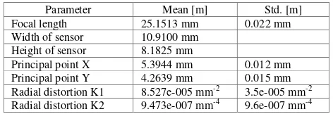
Root mean square of residuals after calibration is 0.16 pixel and maximum residual is 0.59 pixel. These values indicate the quality of achieved results.
Parameter Mean [m] Std. [m]
Focal length 25.1513 mm 0.022 mm
Width of sensor 10.9100 mm
Height of sensor 8.1825 mm
Principal point X 5.3944 mm 0.012 mm
Principal point Y 4.2639 mm 0.015 mm
Radial distortion K1 8.527e-005 mm-2 3.5e-005 mm-2
Radial distortion K2 9.473e-007 mm-4 9.6e-007 mm-4
Table 6. Results of thermo camera calibration
6. TIME SYNCHRONIZATION
6.1 Time delay of digital camera capturing
The delay of the camera's exposure time towards sent remote trigger signal was tested. This delay is necessary to know to adjust the time stamp and allow proper direct georeferencing of the image in the case of camera motion during acquisition. For this purpose we constructed a hardware device which function is similar to the remote trigger. It sends a trigger to camera each two seconds (optional interval) and also runs graphical time counter with a resolution of one millisecond. Graphical time counter (array of three LED bar-graphs) was captured by the camera and the images were subsequently evaluated. The script for evaluation was created in the Matlab programming environment. Images were transformed so the view on the counter field was orthogonal. Then a readout system above image was created, under which red intensity component was evaluated. Position of lighted fields is subsequently transferred to time information about delays.
Figure 11. Graphical time counter on the red monochromatic
Sets of samples were evaluated and the average exposure delay and variance were computed. Variance of delay is important when selecting a camera and shooting mode.
Sensing mode Average
Table 7. Results of Olympus Pen E-PM1 time synchronization
The various settings of camera give standard deviation approximately 5 msec in all cases. At theoretical speed of 15 km/h and a height of 80 m is the uncertainty in georeferencing 2.4 cm,
6.2 Time parameters of thermo camera sensing
In order to use thermo camera Flir SC645 in the project, in applications such as a thermometric orthophoto or thermometric texture from captured images, it is necessary to know the elements of the internal and external orientation just as for digital VIS camera. External orientation can be determined by direct georeferencing, based on the known space-time relationship with the GPS/INS and to determine the time-space relationship is necessary to determine the delay of image capturing towards the trigger signal and its standard deviation. Also the length of capturing is necessary to discover in order to get estimation of blur caused by motion.
6.2.1 Length of exposure delay
To determine length of exposure delay we propose method based on rotational marked wheel with a constant angular velocity. Marks were created from material with different thermal reflectivity (aluminum) compared with matt black base surface. The disc was placed in an optical gate that trigger signal to capture an image and was enlightened by the heat from the black body.
As soon as disk starts to turn optical gate starts to send signal to camera to trigger shutter. There is some delay on the way and we could use differences of marker position on captured image between marker position on reference image (position of disc in which optical gate sends signal) to estimate it.
Differences are evaluated from shits of intensity value under readout circles between reference and actual image. Then time delay is determined with a use of correlation.
Figure 13. Correlation of two intensity signals (reference red, actual blue) on one circle
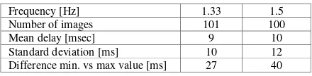
Figure 14. Evolution of time delay for individual images with rotation frequency 1.5 Hz and 1.33 Hz
Frequency [Hz] 1.33 1.5
Number of images 101 100
Mean delay [msec] 9 10
Standard deviation [ms] 10 12
Difference min. vs max value [ms] 27 40
Table 8. Results of time delay determination
Due to the manufacturer reported (FLIR) internal chip frequency 25 Hz there was an assumption that the maximum delay time is 40 msec. Camera can probably also send an image which began to be recorded before the arrival of the trigger signal.
The present results indicate that the average delay time of "accidentally" broadcasted signal is approximately 10 msec and standard deviation reaches the same size as this value. But values in the interval of 40 msec are repeated accurately (it is assumed that the accuracy reach units of msec.) and if the trigger signal is transmitted in multiple interval of 40 msec delay is almost constant.
7. CONCLUSION
The article describes activities which aim to assemble mapping UAV airship. Some of them are finished some of them needs more effort to enhance process and results. Project is about to start to be operational in mid-2013 and it will serve for regular use in academic and private field as well as an education base in future development.
8. REFERENCES
Derenick, J., Miller, T., Spletzer, J., Kushleyev, A., Foote, T., Stewart, A., Bohren, J., Lee, D.: The Sick LIDAR Matlab/C++ Toolbox: Software for Rapidly Interfacing/Configuring Sick LIDARs. Available online:
http://www3.lehigh.edu/images/userImages/jgs2/Page_7287/LU -CSE-08-008.pdf.
FLIR Systems, Inc.. Flir SC645 datasheet. Avaible online: http://mds-flir.com/datasheet/SC645%20datasheet_en.pdf.
Luhmann, T., Ohm, J., Piechel, J., Roelfs, T., 2010: Geometric Calibration of Thermographic Cameras. In: International Archives of Photogrammetry, Remote Sensing and Spatial Information Sciences, Vol. XXXVIII, Part 5, Commission V Symposium, Newcastle upon, Tyne, UK.
SICK AG: LD-OEM Laser Measurement System, Description and Technical Data of LD-LRS1000/2100/3100. Available online: http://sicktoolbox.sourceforge.net/docs/sick-ld-supplement.pdf.
Skaloud, J., Lichti, D., 2006. Rigorous approach to bore-sight self-calibration in airborne laser scanning. ISPRS Journal of Photogrammetry & Remote sensing 61 (2006) 47-59.
9. ACKNOWLEDGEMENTS
The project "Technology and System for Physical and Spatial Characteristics Determination for Protection and Formation of Environment and for Increasing of Energy Sources Potential" number TA01020698 is solved with financial support of Technology Agency of the Czech Republic.