PRECISION ANALYSIS OF POINT-AND-SCALE PHOTOGRAMMETRIC
MEASUREMENTS FOR CORRIDOR MAPPING: PRELIMINARY RESULTS
P. Molinaa,∗, M. Bl´azquez,a, J. Sastrea, I. Colominaa a
GeoNumerics S.L., Parc Mediterrani de la Tecnologia, 08860 Castelldefels (Spain) (pere.molina, marta.blazquez, jaume.sastre, ismael.colomina)@geonumerics.com
ICWG III/I
KEY WORDS:mapKITE, Unmanned Aerial Systems (UAS), Terrestrial Mobile Mapping Systems (TMMS), integrated sensor orien-tation (ISO), corridor mapping
ABSTRACT:
This paper addresses the key aspects of the sensor orientation and calibration approach within the mapKITE concept for corridor mapping, focusing on the contribution analysis of point-and-scale measurements of kinematic ground control points. MapKITE is a new mobile, simultaneous terrestrial and aerial, geodata acquisition and post-processing method. On one hand, the acquisition system is a tandem composed of a terrestrial mobile mapping system and an unmanned aerial system, the latter equipped with a remote sensing payload, and linked through a ’virtual tether’, that is, a real-time waypoint supply from the terrestrial vehicle to the unmanned aircraft. On the other hand, mapKITE entails a method for geodata post-processing (specifically, sensor orientation and calibration) based on the described acquisition paradigm, focusing on few key aspects: the particular geometric relationship of a mapKITE network —the aerial vehicle always observes the terrestrial one as they both move—, precise air and ground trajectory determination —the terrestrial vehicle is regarded as a kinematic ground control point— and new photogrammetric measurements —pointing on and measuring the scale of an optical target on the roof of the terrestrial vehicle— are exploited.
In this paper, we analyze the performance of aerial image orientation and calibration in mapKITE for corridor mapping, which is the natural application niche of mapKITE, based on the principles and procedures of integrated sensor orientation with the addition of point-and-scale photogrammetric measurements of the kinematic ground control points. To do so, traditional (static ground control points, photogrammetric tie points, aerial control) and new (pointing-and-scaling of kinematic ground control points) measurements have been simulated for mapKITE corridor mapping missions, consisting on takeoff and calibration pattern, single-pass corridor op-eration potentially performing calibration patterns, and landing and calibration pattern. Our preliminary results show that the exterior orientation, interior orientation and tie points precision estimates are better when using kinematic control with few static ground control, and even with excluding the latter. We conclude then that mapKITE can be a breakthrough on the UAS-based corridor mapping field, as precision requirements can be achieved for single-pass operation with no need for traditional static ground control points.
1. INTRODUCTION
Unmanned Aerial Systems (UAS) have come to stay among the mapping community (Colomina and Molina, 2014). Small, low-cost and easy-to-operate aerial robots have blossomed since few years ago, and they are now a consolidated technology in our modern society at various levels (from professional to mass-mar-ket niches), just leaving room for questions about its future growth quotes and evolution potential. In the geoinformation sector, sev-eral UAS have established themselves asmust-havesurveyor tools (Sensefly’s Swinglet or eBee, Trimble’s UX-5 or Ascending Tech-nologies’ Falcon-8) and even some consumer-grade platforms are being integrated into the mapping field; e.g., Phantom DJI’s via Pix4D tools. At the end, technical barriers have been broadly overcome as opposite to regulatory ones —the latter have lever-aged the use of UAS in mining and archaeological site survey as well as agriculture, but delayed operations in infrastructure in-spection or urban mapping.
Regarding urban and inter-urban scenarios, high-resolution map-ping has been recently performed with Terrestrial Mobile Map-ping Systems (TMMS) equipped with cameras and/or LiDAR sensors, able to produce 3D geoinformation with high resolution and accuracy relying on direct sensor orientation by means of navigation-grade inertial and GNSS systems. While
high-resolu-∗Corresponding author
tion close-range applications e.g. building facades, have been quite resolved by TMMS (despite the challenge of navigation in harsh urban scenarios), the lack of a “total point of view,” that is, aerial and ground view of the scene, might be a handicap.
To this respect, efforts in fusing Unmanned Aircraft (UA) im-ages with terrestrial imim-ages (P¨uschel et al., n.d.), (Mayer, 2015), or combining 3D models based on UAS images with terrestrial LiDAR ones (Optech, 2015), indicate the feasibility of such an approach to achieve the total point of view from a mapping per-spective. Yet, to our knowledge, there is no approach performing such thing in a simultaneous geodata acquisition mode. More-over, with the current UAS architectures with static ground con-trol station, limitations for the UA-to-station distance (usually, below visual line-of-sight) jeopardizes the mission productivity, specially in the context of long corridors.
aerial control and few image measurements of GCPs, and com-pared to traditional ISO and to direct sensor orientation (DiSO). The method does not rely on tie points between images, which avoids image measurements on ill-textured environments e.g. rivers, sand, trees, etc.
As previously highlighted, our work is devoted to the mapKITE paradigm for sensor orientation in corridors, which follows the trend of precise aerial control but introduces a new type of ground control, and aims at assessing the potential of the concept and identify its benefits and limitations. To do so, section 2 will pro-vide the basics about the mapKITE concept; section 3 presents the modelling aspects that define the mapKITE sensor orientation approach and section 4 exposes the framework for the achieved results.
2. THE MAPKITE ESSENTIALS
The system.A mapKITE system consists of a TMMS and UAS tandem, equipped with remote sensing payloads, and linked by a “virtual tether,” that is, a real-time supply of waypoints derived from the navigation solution of the TMMS and sent to the UAS ground control station to be executed by the UA. Basically, the effect is that of a UA following a terrestrial vehicle. (In other contexts, this technique is known as the ”follow me” UA flying mode.) These waypoints are conveniently set to comply with the mapping mission requirements (image footprint size and overlap, etc.) and potentially perform INS/GNSS and/or camera calibra-tion maneuvers. In mapKITE, the UAS ground control stacalibra-tion is mobile, carried by the TMMS vehicle thus optimizing the line-of-sight conditions, necessary for the communication link and for safety aspects. In particular, this configuration enables UAS oper-ation far beyond the starting point, in contrast to the usual [static] UAS configurations. The result is a “mapping kite” with a total point of view, from ground to air, targeting at corridor mapping applications such as mapping of roadways, railways, waterways and other linear structures. In these cases, the continuous-line-of-sight nature of the system is a productivity booster and a concept differentiator. More details about the concept and its current im-plementation can be found in (Molina et al., 2015).
New measurements within a new paradigm.One key element of a mapKITE system is an optical target placed on the roof of the terrestrial vehicle. Based on the concept of coded targets fea-turing fast and robust identification in images for target track-ing (Cucci et al., 2015), the target enables image measurement in two different ways,pointing—classical photogrammetric mea-surement of the target— andscaling—metric measurement of the image projection of the target in relation to the original target or, put simply, measurement of the scale of a point in an im-age. Additionally, these image measurements can be associated to precise global coordinates by means of the post-processed nav-igation solution of the TMMS. Consequently, the target shall be interpreted as a Kinematic Ground Control Point (KGCP) that ex-tends the classic concept of Static Ground Control Point (SGCP) by physically moving in solidarity with the terrestrial vehicle and, thus, being potentially measured in every image. Note also that, in these conditions, obtaining motionless KGCPs (an analogy to traditional GCP) is as simple as stopping the terrestrial vehicle yet much cheaper than surveying techniques. Precisely, the po-tential of this new type of ground control, the KGCP, through its point-and-scale image measurement is the object of study of the present work.
Stop-and-go calibration in missions.When considering multi-copter platforms for mapKITE, one may think of a typical mis-sion starting with an ascent to a nominal operational height and
end with a descent to ground. During these two phases, calibra-tion maneuvers, e.g. bearing turns and short translacalibra-tions, can be done while the terrestrial vehicle in motionless. Additionally, a mapKITE operator may even stop the terrestrial vehicle (and con-sequently, the UA) during the mission and command such cali-bration maneuvers aiming at strengthening the measurement net-work on those points and help with the process of self-calibration.
Navigation approach. Precision, accuracy and reliability of the mapKITE aerial and ground trajectories is instrumental in many aspects, covering real-time to post-mission. To this respect, the use of modern and modernized GNSS systems is addressed by combining reliable GPS signals with the accuracy and multipath-resistant properties of the new GNSS like Galileo or Beidou. Re-garding navigation of the UA, a hybrid INS/GNSS concept is en-visioned, enhanced by using the European Geostationary Nav-igation Overlay Service (EGNOS) that provides real-time GPS differential corrections to improve accuracy and ensure integrity of the GNSS signals. In relation to the generation of the UA waypoints by the terrestrial vehicle, the use of the Galileo E5 AltBOC (15,10) signal and modulation is of particular interest because of its robustness against multipath errors. Additionally, its 2 cm noise pseudorange shall contribute to the quality of the post-mission ground trajectory determination, which is the source of the KGCP measurements.
3. SENSOR ORIENTATION AND CALIBRATION APPROACH
As already discussed, the mapKITE control configuration con-cept includes the usual control components of integrated sen-sor orientation —aerial control with a constant shift GNSS error model and ground control (the SGCPs)— plus the KGCPs. More-over, since the KGCPs are materialized with targets of known size and shape, point-and-scale photogrammetric measurements can be made for the KGCPs. In short, a mapKITE ISO extends the usual ISO of aerial blocks by using KGCPs and their point-and-scale photogrammetric measurements. All this, together with calibration image sequences whose images are taken at different altitudes during landing and takeoff maneuvers, opens the door to the self-calibration of the interior orientation (IO) parameters as the geometry of the resulting network is rather strong.
In this article we report on preliminary research results rather than pursuing a comprehensive analysis on precision, accuracy —i.e., feasibility of calibration of systematic errors— and reliability [of the new type of measurements]. We have therefore made a num-ber of assumptions on the precision of the input measurements and on the trajectory shape of the terrestrial-aerial vehicle tan-dem (confer section 4). Similarly, we have made assumptions on the stability properties of the aircraft camera(s) which, obviously, are camera dependent and that, in some cases, may totally deviate from our assumptions. More specifically, we have assumed that IO parameters are unstable from flight to flight but stable within a flight; i.e., a block-to-block variant and in-block invariant IO hypothesis. We have also assumed that radial and tangential dis-tortions can be calibrated off-line, with lab- or field-calibration strategies, in a way that the parameters of their modeling func-tions —e.g., thek1,k2,k3,p1andp2parameters of the
Conrady-Brown model— are sufficiently decorrelated from the IO param-eters. This can be achieved with an appropriate acquisition ge-ometry.
With the above assumptions we try to emulate the situation of high-end, off-the-shelve cameras and high-end, off-the-shelve len-ses of fixed focal length. This is a reasonable setup in the context
Coordinate Reference Frames
l Cartesian local geodetic frame (Easting-Northing-height) c Cartesian camera instrumental frame (forward-left-up)
Parameters
Pl= (E, N, h)l
ground point inl-frame
P0l= (E0, N0, h0)l camera projection centre (l-frame)
Rl
c(ω, φ, κ) camera attitude matrix (parameterized by the Euler angles(ω, φ, κ)l
c (∆x0,∆y0,∆c)c interior orientation biases (c-frame)
Observations
ℓx, ℓy, ℓλ image coordinates and scale observations ofPl νx, νy, νλ image coordinates and scale residuals ofPl
Instrument constants
x0, y0, c principal point coordinates and camera constant
Table 1: Coordinate reference frames, parameters, observations and instrument constants.
of the mapKITE missions and the targeted corridor mapping ap-plications.
Last but not least in our orientation and calibration approach, is the mathematical model for point-and-scale photogrammetric measurementsℓx, ℓy, ℓλthat we will use for the KGCPs and that can be written in the obvious form
Pl=P0l+ (ℓλ+νλ)·Rlc·
ℓx+νx−(x0+ ∆x0)
ℓy+νy−(y0+ ∆y0) −(c+ ∆c)
c
(1)
whereℓλis the measured image scale factor at pointPl. The meaning of the rest of variables and reference frame symbols in the previous equation are described in Table 1.
4. SIMULATED CORRIDORS AND RESULTS
In order to understand the general properties and overall contri-bution of the new measurement types introduced for mapKITE, KGCPs and point-and-scale photogrammetric measurements, we have simulated single-strip corridor blocks by generating mea-surements for all required observables as detailed in table 2.
Seasoned researchers and practitioners know what simulations can tell and what they can be made to tell. Keeping this in mind and with the goal of developing a realistic —non-optimistic or, at least, not too optimistic— insight and intuition on the behavior of mapKITE blocks, we have “designed” a block which can be ma-terialized from an operational standpoint and we have assigned measurement precisions which are attainable, rather pessimistic than optimistic, under operational conditions.
Table 2 summarizes the mission design parameters and the preci-sion of the simulated measurements, and table 3 summarizes the results of the simulations for each simulated corridor. We discuss them in the next sections.
4.1 Block design
As described in table 2, we have simulated a 5 km, single-strip, rectilinear, 80% forward overlap block, acquired from an altitude of 100 m over flat terrain with camera parameters close to the popular Sony NEX-7 camera and a 20 mm camera constant lens
Observables Precision Units
Static GCP (SGCP)
-σE,N 3 cm
-σh 5 cm
Kinematic GCP (KGCP)
-σE,N 6 cm
-σh 10 cm
Tie Point Image Coordinates
-σx,y 3 µm
0.77 px
Point-and-scale coordinates of KGCP
-σx,y 3 µm
0.77 px
-σλ 100 ppm
GNSS aerial control
-σE,N 3 cm
-σh 5 cm
Mission design parameters Name/Value Units
Equipment (UA camera) Sony NEX-7
-Equipment (TV navigation) GNSS receiver geodetic grade -Equipment (UA navigation) GNSS receiver
geodetic grade
-Sensor size 23.5 x 15.6 mm
6000 x 4000 px
Pixel size 3.9 µm
Camera constant 20 mm
Corridor length 5 km
Corridor flying height 100 m
Base-to-height ratio 0.15
-No. of bases 328
-Calibration maneuvers start & end
-Ground Sampling Distance (GSD) 2 cm
Forward Overlap 80 %
Table 2: Precision of observables and mission design parameters.
Image tie point measurements are uniformly distributed along the image, and KGCPs correspond to the trajectory of a terrestrial vehicle “paired” to the UA trajectory, as in a mapKITE mission. SGCPs have been generated as pairs of points, aligned with the across-track direction, and distributed along the corridor with a separation of 900 metres. Since, in mapKITE, the aircraft is a multicopter, we have simulated maneuvers for image calibra-tion; that is, sets of images taken during short ascent from or de-scent to 50 m, combined with horizontal translations and heading turns. These maneuvers are always feasible at the start and end of a mapKITE mission coinciding with the takeoff and landing phases. In fact, as already mentioned, it is always possible —and potentially beneficial— to stop the mission for a short period of time, in which the aircraft repeats the calibration maneuver while the terrestrial vehicle remains static. In this case, a KGCP be-comes a SGCP.
4.2 Precision of measurements
=3 cm,σh =5 cm). We have assumed that KGCPs are mea-sured with equivalent surveying equipment as the SGCPs. How-ever, even with identical equipment, kinematic positioning is less precise than its static counterpart and, in a corridor mapping mis-sion, GNSS signal fading —if not signal occlusions— may occur further resulting in less precise measurements because of a lower signal-to-noise ratio. Therefore, we have given KGCPs a larger random error (σE,N=6 cm,σh=10 cm). In both cases, SGCPs and KGCPs, we have assumed that they are accurate since short periods of static measurements for GNSS integer ambiguity res-olution can always be implemented.
We have restricted aerial control to position control since, at this point in time of mapKITE research, we did not want to add an equipment requirement (IMU) to the unmanned aircraft payload that may prove to be not strictly necessary. (This is arguable. However, in any case, inertial measurements would just bring improvement upon the reported results.) Following the usual ap-proach of airborne photogrammetry we have assumed that the aircraft is equipped with a geodetic grade GNSS receiver, which for state-of-the-art receivers, translates into a multi-constellation and multi-frequency receiver. GNSS measurements are assumed to be processed under the Precise Point Positioning (PPP) mode which is more precise but less accurate than differential carrier phase methods. Eventual systematic errors of PPP are modeled with the usual shift parameters. According to these we have as-signedσE,N =3 cm andσh =5 cm to aerial control. (This is also arguable since differential processing might be also per-formed for short periods when the aircraft is on ground, to avoid large inaccuracies. Again, such an approach would just improve upon the reported results.)
Image coordinate measurements for natural and targeted tie points have been given an approximate precision ofσx,y≈1 px, clearly on the conservative side. Last, we have set a precision ofσλ ≈ 100 ppm for the scale component of the point-and-scale measure-ments. The value is rather speculative, based on the expected pre-cision of matching contours to extracted target edges. However, the simulations conducted so far, indicate that the parameter pre-cision is rather insensitive toσλ. For instance, settingσλ≈1000 ppm deteriorates slightly ground point vertical accuracy (17%) —although augments its redundancy number, from 4% to 54%.
4.3 Software
Observation equation 1 has been implemented in the airVISION model toolbox of GeoNumerics’ generic network adjustment plat-form GENA (Colomina et al., 2012). The rest of the mathe-matical models used in the simulations were already available in airVISION. The simulations themselves have been performed with GENA and airVISION.
4.4 Simulated configurations
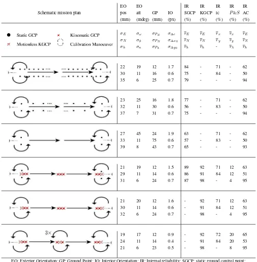
In order to facilitate the understanding of the essential proper-ties of the mapKITE orientation and calibration method, we have selected six plus one representative configurations of mapKITE missions. The selection aims also at the comparison between the traditional way of designing a corridor mapping mission (row 1), corridors featuring, long to too long GCP bridging (rows 2 and 3) and some candidate mapKITE configurations with KGCPs (rows 4, 5 and 6). The configurations correspond to the six rows of Table 3 and the single row of Table 4 respectively. All configura-tions include, at least, two camera calibration maneuvers, one for each end of the strip; one of them (Table 3, row 6) includes three additional ones.
The first configuration (Table 3, row 1) corresponds to a map-KITE flight whose orientation and calibration have been obtained in the traditional way, i.e., by using GNSS aerial control and SGCPs, at the ends of and within the strip. The bridging distance between pairs of GCPs is about 13 bases or 195 m. This configu-ration aims at being representative of non-mapKITE, traditional, as said, methods.
The second configuration (Table 3, row 2) is configuration 1 with less GCPs, with bridging distance between pairs of GCPs of about 60 bases or 900 m. It is an in-between configuration among the first and third configurations with the only purpose of illustrating the trade-offs between GCP density and performance.
The third configuration (Table 3, row 3) results from removing all GCPs but those at the strip ends. Bridging distance between pairs of GCPs is, therefore, 320 bases or the length of the strip. This configuration serves the purpose of illustrating the role of GCPs and the improvement brought by KGCPs. It is not representative of real-life situations and will not be used to draw conclusions.
The fourth configuration (Table 3, row 4) is our flagship. (It will result in being our recommended configuration.) This configu-ration includes just two pairs of GCPs at the strip ends and one KGCP for each image with its associated point-and-scale pho-togrammetric measure.
The fifth configuration (Table 3, row 5) is the fourth one without GCPs.
The sixth configuration (Table 3, row 6) adds three aircraft ma-neuvers with static terrestrial vehicle to the previous configura-tion, and in practice, also to the fourth one. Its goal is to quantify the improvement brought into the determinability of the calibra-tion parameters, their redundancy numbers of the point-and-scale measurements and any possible significant improvement in the parameters of interest, ground points and exterior orientation pa-rameters.
The last configuration (Table 4) is almost equivalent to configu-ration 4, the only difference being the precision of the scale mea-surement which, in this case isσλ=1000 ppm instead ofσλ= 100 ppm.
4.5 Simulation results
We provide Table 3 to present, on one side, a schematic view of the mission plan phases of the simulated blocks and, on the other hand, the estimated precision results for the relevant parameters of interest —Exterior Orientation (EO), Ground Points (GP) and Interior Orientation (IO)— together with the Internal Reliability (IR) for every measurement listed in 2. Yet, we provide additional explanations hereafter:
• The initial cell (first row, first column) depicts the symbols for SGCPs, KGCPs, calibration maneuvers and motionless KGCP symbols. Recall that aerial control and tie points are present in all corridors (thus not made explicit),
• The rest of the cells in the first row list the used estimators for precision (mean of the standard deviations) and internal reliability (mean of redundancy numbers) for each measure-ment,
• The rest of the rows describe the actual results following the model in the first row for the simulated blocks.
The main result is that with the mapKITE orientation and calibra-tion method (the mapKITE ISO), we obtain the same results, if not slightly better, as with the traditional ISO method with dense GCPs. Moreover the redundancy numbers of the measurements in the mapKITE ISO are high with the exception of point-and-scale measurements that range between 4% and 54%.
In table 3, first, we observe the expected results for traditional ISO in the described corridor conditions: the precision of the EO position wanders around the precision of the aerial and ground control, a strong heading angle determination and a lower pre-cision of the across-track component of the ground points. Mea-surement redundancy numbers are considered within expectations. Secondly, we observe also the effect of increasing the ground control bridging in rows 2 and 3, which is a degradation of the across-track ground point coordinates and of the EO attitudeω angle, while the EO position is still dominated by the aerial con-trol. We observe a decrease of the SGCP redundancy, as we as we decrease the number of GCPs.
When KGCPs are introduced and measured, that is, performing mapKITE ISO, we immediately observe a precision improvement of all the estimated parameters as compared to traditional ISO, even with short bridging distances (row 1). In particular, a re-markable effect on ground point precision is observed. Addition-ally, we observe that the redundancy numbers of SGCP measure-ments are higher in presence of KGCPs. As a matter of fact, we observe by the results in row 5 that even without SGCP, mapKITE ISO leads to the same results as traditional ISO with high SGCP density. We do not recommend, though, this configuration and tend to favor configuration 4 as static GCPs have proven to be an excellent tool against GNSS receiver malfunctions, weak geome-tries, frequent datum mistakes, etc. Moreover, it is feasible from an operational standpoint as the corridor ends usually correspond to system set-up periods where surveying measurements can be taken confortably.
Regarding the calibration of the IO parameters, we observe some benefit with the addition of calibration maneuvers in the middle of the strip, as in row 6. Whether this improvement, in practice, is significant or not we shall see in the future. In any case, camera calibration maneuvers with a multicopter is a low-cost operation and supposes a low impact in aerial corridor mapping missions.
We also provide measurement redundancy numbers to analyze the contribution of these new measurements as compared to the traditional ones (table 3, right columns). First of all, we observe a high redundancy for KGCPs. This indicates a good condition for error identification through regression diagnostics mechanisms, which is convenient for mapKITE as we expect the terrestrial ve-hicle trajectory to be a major source of errors. Secondly, we ob-serve (table 3) a low redundancy of the point-and-scale measure-ment, which indicates a strong influence of such measurements with respect to the rest. However, in table 4, forσλ=1000 ppm, the scale measurement mean redundancy number goes up to 54% due to its lower weight at the expected expense of a less pre-cise vertical component determination. Admittedly, at the current stage of this research, we have not rigorously characterized the precision of the scale measurement. In any case, double KGCP targeting results in significant higher redundancy numbers.
5. SUMMARY AND PRELIMINARY CONCLUSIONS
We have described the mapKITE orientation and calibration con-cept that we also call the “mapKITE ISO” and have performed simulations with rather conservative assumptions on the quality of the input measurements to understand its potential benefits.
The simulations indicate, that the mapKITE ISO can replace tra-ditional ISO with great savings in time and money for corridor mapping projects.
The research leading to these results has been funded by the Eu-ropean Community Horizon 2020 Programme under grant agree-ment no. 641518 (project mapKITE,www.mapkite.com) man-aged by the European GNSS Agency (GSA).
MapKITE has been patented by GeoNumerics (Spanish patent 201231200) and further PCT applications have been filed to cover Europe, United States and Brazil.
REFERENCES
Bl´azquez, M. and Colomina, I., 2012. Performance analysis of Fast AT for corridor aerial mapping. ISPRS - International Archives of the Photogrammetry, Remote Sensing and Spatial In-formation Sciences XXXIX-B1, pp. 97–102.
Colomina, I. and Molina, P., 2014. Unmanned aerial systems for photogrammetry and remote sensing: A review.{ISPRS}Journal of Photogrammetry and Remote Sensing 92, pp. 79 – 97.
Colomina, I., Bl´azquez, M., Navarro, J. and Sastre, J., 2012. The need and keys for a new generation network adjustment software. ISPRS - International Archives of the Photogrammetry, Remote Sensing and Spatial Information Sciences XXXIX-B1, pp. 303– 308.
Cucci, D., Constantin, D. and Rehak, M., 2015. Smile targets in aerial photogrammetry. In: Proceedings of the International Micro Air Vehicle Conference and Competition, Vol. 54, Aachen, Germany.
Delair Tech, 2014. Power lines inspection using mini-UAV. On-line athttp://goo.gl/NK5zZq; accessed 25-January-2015.
Mayer, H., 2015. From Orientation to Functional Modeling for Terrestrial and UAV Images. In: 55th Photogrammetric Week, Institut f¨ur Photogrammetrie, Universit¨at Stuttgart, pp. 165–174.
Molina, P., Bl´azquez, M., Sastre, J. and Colomina, I., 2015. A method for simultaneous aerial and terrestrial geodata acquisition for corridor mapping. ISPRS - International Archives of the Pho-togrammetry, Remote Sensing and Spatial Information Sciences XL-1/W4, pp. 227–232.
Optech, 2015. ILRIS Terrestrial Laser Scanner Integrating UAV Camera Imagery. Online athttp://goo.gl/ERIsA9; accessed 25-January-2015.
P¨uschel, H., Sauerbier, M. and Eisenbeiss, H., n.d. A 3D model of Castle Landenberg (CH) from combined photogrammetric pro-cessing of terrestrial and UAV-based images. Vol. XXXVII-B1, Beijing, China, pp. 963–970.
Rehak, M. and Skaloud, J., 2015. Fixed-wing micro aerial vehicle for accurate corridor mapping. ISPRS - International Archives of the Photogrammetry, Remote Sensing and Spatial Information Sciences.
Schematic mission plan
EO EO IR IR IR IR IR
pos att GP IO SGCP KGCP ic P&S AC
(mm) (mdeg) (mm) (px) (%) (%) (%) (%) (%)
σE σω σPE σ∆c rE rE rx rx rE
σN σφ σPN σ∆x0 rN rN ry ry rN
σh σκ σPh σ∆y0 rh rh - rλ rh
22 19 12 1.7 84 - 71 - 62
30 11 16 0.6 75 - 84 - 50
35 6 25 0.7 79 - - - 94
23 25 16 1.8 77 - 71 - 62
32 11 30 0.6 56 - 83 - 50
37 7 31 0.7 75 - - - 94
27 45 24 1.9 63 - 71 - 62
33 11 75 0.6 57 - 83 - 50
39 8 43 0.7 65 - - - 93
21 19 12 1.5 89 92 71 12 63
29 11 14 0.6 86 91 84 12 51
31 6 24 0.7 87 98 - 4 95
21 20 12 1.6 - 92 71 12 63
30 11 14 0.6 - 91 84 12 51
32 6 24 0.7 - 98 - 4 95
19 17 12 0.9 - 92 72 20 65
24 11 14 0.4 - 91 84 20 53
21 6 23 0.5 - 98 - 8 95
EO: Exterior Orientation; GP: Ground Point; IO: Interior Orientation; IR: Internal reliability; SGCP: static ground control point; KGCP: kinematic ground control point; ic: image coordinates; P&S: point-and-scale; AC: aerial control
Table 3: Precision and internal reliability results for the mapKITE corridors, varying SGCPs, KGCPs and calibration manoeuvers.
Schematic mission plan
EO EO IR IR IR IR IR
pos att GP IO SGCP KGCP ic P&S AC
(mm) (mdeg) (mm) (px) (%) (%) (%) (%) (%)
21 20 12 1.6 88 92 71 12 63
30 11 14 0.6 86 91 84 12 50
32 6 29 0.7 86 98 - 54 94
Table 4: Precision and internal reliability results for the mapKITE corridor usingσλ= 1000ppm.