379
15
Closed-Loop Spatial Audio Coding
Ikhwana Elitri
Having in mind the growing demand for the reliable delivery of high- quality multichannel audio in various multimedia applications such as home enter-tainment, digital audio broadcasting, computer games, music streaming ser-vices as well as teleconferencing, eficient coding techniques [1] have become paramount in the audio processing arena. The traditional approach for com-pressing multichannel audio has been to encode each audio channel using a mono audio coder, such as Dolby AC-3 and MPEG advanced audio coder (AAC) [2]. However, for the majority of coders adopting this method, the number of bits to be transmitted tends to increase linearly with the number of channels.
Recently, a new concept for encoding multichannel audio signals has been proposed. It comprises the extraction of the spatial cues and the downmixing
CONTENTS
15.1 Overview of MPEG Surround ...380
15.1.1 Spatial Analysis and Synthesis ... 382
15.1.2 Quantization and Coding ...384
15.2 Closed-Loop R-OTT Module ... 386
15.2.1 Analysis-by-Synthesis Framework ... 386
15.2.2 R-OTT Module within AbS-SAC Framework ... 387
15.3 Simpliied AbS Algorithm ... 388
15.3.1 Full Search AbS Optimization ... 388
15.3.2 An Approach for Algorithm Simpliication ... 389
15.3.3 Basic Scheme of the Encoder ... 390
15.3.4 Suboptimal Algorithm ... 392
15.3.5 Complexity of Sub-Optimal Algorithm ... 393
15.4 Results ... 393
15.4.1 Evaluation of Closed-Loop R-OTT Module ... 395
15.4.2 Evaluation of Sub-Optimal Algorithm ... 396
15.4.3 Objective Evaluation ... 396
15.4.4 Subjective Evaluation ... 398
15.4.5 Complexity Assessment ... 399
15.5 Conclusions ... 399
References ...400
380 Mixed-Signal Circuits
of multiple audio channels into a mono or stereo audio signal. The down-mix signals are subsequently compressed by an existing audio encoder and then transmitted, accompanied by the spatial cues coded as spatial param-eters. Any receiver system that cannot handle multichannel audio can simply remove this side information and just render the downmix signals. This pro-vides the coder with backward compatibility, which is important for imple-mentation in various legacy systems. In addition, by utilizing the spatial parameters, the downmix signals can be directly upmixed at the decoder side into a multichannel coniguration that may be different from the one used at the encoder side. This technique is known as spatial audio coding (SAC).
Various SAC techniques, such as binaural cue coding (BCC) [3] and MPEG 1/2 layer 3 (MP3) Surround [4], have been proposed. Interchannel level dif-ference (ICLD), interchannel time difdif-ference (ICTD), and interchannel coher-ence (ICC) are extracted as spatial parameters that are based on human spatial hearing cues. Techniques such as parametric stereo (PS) [5] and MPEG Surround (MPS) [6,7] may also utilize signal processing techniques, such as decorrelation. The great beneit of these perceptual-based coders is that they can achieve bitrates as low as 3 kb/s for transmitting spatial param-eters, as in the case of MPS.
As one can observe, each of these coding techniques has its unique advan-tages and disadvanadvan-tages. However, they can all be classiied as open-loop systems, where the encoders of BCC, MP3 Surround, and MPS do not con-sider the decoding process during encoding. The major drawback of an open-loop system is that there is no mechanism employed to reduce the error introduced by quantizing the spatial parameters and coding the downmix signals. In this chapter, an analysis by synthesis spatial audio coding (AbS-SAC) technique is presented, which provides the advantages of a closed-loop system in order to improve the quality of multichannel audio reproduction. We believe that the AbS-SAC technique can be implemented in any of the recent SAC schemes, even though in this work the AbS-SAC is applied solely in the context of the MPS architecture.
The rest of this chapter is organized as follows. Section 15.1 provides an overview of MPS. Subsequently, the closed-loop R-OTT module and the sim-pliied AbS algorithm are presented in Sections 15.2 and 15.3, respectively. Experiments that prooing the proposed methods and results are given in Section 15.4 followed by conclusions in the last section.
15.1 Overview of MPEG Surround
To provide a meaningful illustration, a basic block diagram of MPS is shown in Figure 15.1. An analysis quadrature mirror ilterbank (A-QMF) is used to decompose the audio signal in each channel into subband signals, while a
Q1
3
Ch. 1 A-QMF Downmix signals Downmix signals
Audio
Block diagram of MPEG Surround.
K24255_C015.indd 381
382 Mixed-Signal Circuits
synthesis QMF (S-QMF) is used to transform them back into a time-domain signal. Considering the importance of reducing the number of audio chan-nels, multiple audio signals at the encoder side are typically downmixed into a mono or stereo signal, which can be further encoded by any kind of audio coder such as MP3 and high-eficiency advanced audio coder (HE-AAC). The major beneit of downmixing audio channels is a possibility to employ an existing, legacy audio coder, allowing backward compatibility. In order to be capable of creating back all audio channels at the decoder side, channel level differences (CLDs), ICCs, and channel prediction coeficients (CPCs) must be extracted as spatial parameters and transmitted as side information of the downmix signal. Furthermore, residual signal can be computed as error compensation due to downmixing process and transmitted to the decoder for enabling high-quality audio reconstruction. Interestingly, when operat-ing at lower bitrates the residual signal can be ignored and replaced in the decoder by a synthetic signal constructed using a decorrelator.
15.1.1 Spatial Analysis and Synthesis
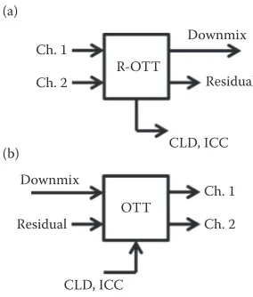
The MPS system comprises two pairs of elementary building blocks for channel conversion and the reverse process: one-to-two (OTT) and two-to-three (TTT) modules. The OTT module is used to convert a single channel to two channels while the TTT module is used to convert two channels to three channels. The reverse conversions are done by the reverse OTT (R-OTT) mod-ule and the reverse TTT (R-TTT) modmod-ule. CLDs, ICCs, and residual signal are extracted from the R-OTT module, whereas CPCs, ICCs, and residual signal are calculated from the R-TTT module. The whole process in the encoder and decoder is built up by combining several OTT and TTT modules in a tree structure. This section simply describes the extraction of CLD, ICC as well as residual signal, as they are implemented within the proposed framework. For further details on CPC the readers can refer to ref. [10].
The schematics of the OTT and R-OTT modules are depicted in Figure 15.2. The R-OTT converts two input channels into one output channel and then extracts CLD and ICC as spatial parameters. Conversely, the OTT re-synthe-sizes two channels from one channel, utilizing the spatial parameters.
The irst spatial parameter, CLD denoted as C, relates energies of the audio signals in the irst and second channels which can be written as
C e
x2[n], respectively. For transmission, the quantized logarithmic values of the
CLDs are conveyed. The second spatial parameter, ICC denoted as I, relects
383 Closed-Loop Spatial Audio Coding
the degree of correlation between both input channels which can be deter-mined by
The downmix signal y[n] is a scaled sum of the input signals. One possible representation of the downmix signal can be written as
y n x n x n
a b
[ ]= 1[ ]+ 2[ ]
+ (15.3)
where the energy constants a and b are calculated as ( )2 1 2 2 1 2
representing the energy preservation constraint [10].
Furthermore, the residual signal r[n] is determined from the following decomposition:
Block diagram of (a) the OTT module and (b) the R-OTT module as used in MPS.
384 Mixed-Signal Circuits
At the decoder side, both audio signals are recreated by estimating a and
b as follows:
ˆ cos
a=X (A+B) (15.7)
ˆ cos
b =Y (A−B) (15.8)
where the X, Y, A, and B variables given as
X C
C
= ˆ ˆ
1+ (15.9)
Y
C
= 1
1+ ˆ (15.10)
A = 1 I
2arccos( )
ɵ
(15.11)
B X Y
X Y A
= tan − − arctan +
( ) (15.12)
are determined from the quantized values of CLD, Cɵ, and the quantized values of ICC, Iˆ. Hence, both signals can be reconstructed as
ˆ ˆ ˆ ˆ
x n1[ ]= ay n[ ]+r n[ ] (15.13)
ˆ ˆ ˆ ˆ
x n2[ ]=by n[ ]−r n[ ] (15.14)
which are similar to Equation 15.5 but use the decoded downmix and resid-ual signals, y nˆ[ ] and r nˆ[ ], respectively.
15.1.2 Quantization and Coding
The logarithmic value of the extracted CLD, calculated as 10 ⋅ log
10(C), is
represented using one of the following nonuniform quantization values: CLD =[ 150, 45, 40, 35, 30, 25, 22, 19, 16, 13, 10, 8,
6, 4
− − − − − − − − − − − −
− − ,, 2, 0, 2, 4, 6, 8,10,13,16,19, 22, 25, 30, 35, 40, 45,150]−
385 Closed-Loop Spatial Audio Coding
where ive bits are allocated to send the index of this quantized CLD. Additionally, the extracted ICC, I, is represented by one of the following nonuniform quantization values:
ICC=[ 0.99, 0.589, 0, 0.36764, 0.60092, 0.84118, 0.937,1]− −
where three bits are allocated for transmitting the index of the quantized ICC.
The residual signal is encoded in the same way as in LC-AAC. The MPS standard speciies the transformation of the residual signal from the sub-band domain to the spectral coeficients of the MDCT transform. A frame, comprised of 1024 spectral coeficients, is segmented as scale factor bands, whereas many as 49 scale factor bands are used.
For each band, a scale factor is determined and the spectral coeficients are quantized as follows:
where ix[k] is the quantized spectral coeficient with its value limited from
−8191 to +8191, r[k] is the spectral coeficient of the residual signal, and SF is
the scale factor. Consequently, 14 bits are required to represent the index of the quantized value. The quantizer may utilize a psychoacoustic model to compute the maximum allowed distortion while an analysis by synthesis procedure is carried out to select the best scale factor and quantized spectral coeficient, resulting in a minimal error.
Huffman coding is then carried out for further compression where several Huffman codebooks, designed for different sets of spectral data, are pro-vided. The quantized spectral coeficients of one or more scale factor bands are grouped and then encoded with an appropriate codebook depending on the maximum absolute value of the quantized spectral coeficients within the group. Groups that have all of their quantized spectral coeficients at zero values are associated to codebook 0, where all of the quantized spec-tral coeficients within this group do not need to be transmitted. Particular attention is given to the last codebook which is provided for groups with the maximum absolute values greater than or equal to 16 when a special escape sequence is used. A set of n-tuples of quantized spectral coeficients within a group, consisting of either two or four coeficients, are then represented as Huffman codewords. To keep their size small, most codebooks are given unsigned values. Thus, the sign of each nonzero coeficient is represented as an additional bit appended to the unsigned codeword.
386 Mixed-Signal Circuits
15.2 Closed-Loop R-OTT Module
15.2.1 Analysis-by-Synthesis Framework
Analysis-by-synthesis (AbS) technique is a generic method that has already been implemented in many areas, such as estimation and identiication. Several decades ago, this concept was proposed as a framework for encod-ing speech signals and determinencod-ing the excitation signal in a linear predic-tive coding (LPC)-based speech coder. Since then, many other speech coders have been proposed within this framework, such as the most popular code-excited linear prediction (CELP), which is currently speciied as one of the tools in the MPEG-4 Audio standard. CELP is also currently adopted in the development of the MPEG standard, ISO/IEC 23003-3/FDIS, Uniied Speech and Audio Coding (USAC). The AbS technique is currently applied in many applications, including the quantization of spectral coeficients of the MPEG-AAC audio codec.
An AbS system is able to synthesize a signal by a set of parameters where the values of these parameters are usually made variable in order to produce the best-matched synthesized signal. The difference between the observed signal and the synthesized signal, called the error signal, is utilized in an error minimization block. A set of parameters which produce minimum error signal are selected as optimal parameters and sent to the decoder.
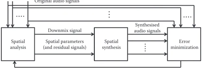
The framework of the AbS-SAC is given in Figure 15.3. A spatial synthesis block, similar to that performed at the decoder side, is embedded within the AbS-SAC encoder as a model for reconstructing multichannel audio signals. Assuming that there is no channel error, the audio signals synthesized by the model in the encoder will be exactly the same as the reconstructed audio signals at the decoder side. The error minimization block is used to compare the input signals with the reconstructed signals based on a suitable criterion such as mean squared-error (MSE) or other perceptual relevant criterion.
Original audio signals
Spatial synthesis Spatial
analysis
Error minimization Synthesised
audio signals
Spatial parameters (and residual signals)
Downmix signal
FIGURE 15.3
Framework of analysis-by-synthesis spatial audio coding (AbS-SAC).
387 Closed-Loop Spatial Audio Coding
The resultant downmix and residual signals as well as the optimal spatial parameters are then transmitted to the decoder.
Based on this framework, various implementations are possible. They are listed as follows:
• Any approach of spatial analysis and synthesis can be implemented. • Different numbers of input and output channels can also be used. • Various types of suitable error criterion can be utilized.
• For taking into consideration the error introduced in the communi-cation channel, a block modeling the channel error can be inserted between the spatial analysis and synthesis block.
• The AbS-SAC approach can be implemented for only a single param-eter recalculation without multiple iterations. This can be considered as a modiication to the original open-loop spatial analysis block. • The implementation can be intended to ind the optimal synthesized
signals by performing the trial and error procedure. Either the origi-nal blocks or the adapted version of the spatial aorigi-nalysis and synthe-sis can be applied.
15.2.2 R-OTT Module within AbS-SAC Framework
The OTT and R-OTT modules, as used in MPS, can be implemented within the AbS-SAC framework, where two channels of the original audio signals are fed to an R-OTT module as the spatial analysis block. On the other hand, the OTT module is performed as the spatial synthesis block for reconstruct-ing two channels of synthesized audio signals, so that Equation 15.8 becomes the formula of the model. In this chapter, this is referred to as a closed-loop R-OTT module where a new optimized downmix signal can be approxi-mated as
y n x n x n
a b
new[ ]
[ ] [ ]
1 2
= +
+
ˆ ˆ (15.16)
Moreover, based on the new optimized downmix signal Equation 15.5 can be used to obtain the expression for the new optimized residual signal as
rnew[ ]n = x n1[ ]−ayˆ new[ ]n = byˆ new[ ]n −x n2[ ] (15.17)
where either x n1[ ]− aɵynew[ ]n or byˆ new[ ]n −x n2[ ] can be used to determined rnew[n]. If both input signals have the exact same magnitude but
oppo-site phases (i.e., x1[n] =−x2[n]), then the downmix signal has all-zero
val-ues, ynew[n] = 0. Consequently, the residual signal can be determined as
388 Mixed-Signal Circuits
rnew[n] =x
1[n] =−x2[n], and a speciic information has to be transmitted to the
decoder conveying this information.
The proposed closed-loop R-OTT algorithm relies on an approximation in Equation 15.16 when recalculating the downmix signal as a new, optimized signal, ynew[n]. Therefore, the signal distortion reduction process is based on how to create the new optimized downmix signal on the encoder side, such that the synthesized downmix signal on the decoder side fulils the desired criteria. In practice, this is achieved by ensuring that the approxima-tion error, which is the difference between the synthesized downmix signal,
ˆ
y n[ ], and the new optimized downmix signal, ynew[n], is minimized. In order to obtain the minimum approximation error, both the synthesized and the approximated signals should be synchronized and compared.
The closed-loop R-OTT method is ideally capable of considerably mini-mize the error introduced by the quantization process of the spatial param-eters. This is because the new optimized downmix and residual signals,
ynew[n] and rnew[n], are computed based on estimated energy constants, aˆ and ˆ
b, so that the quantization errors of CLD and ICC are now compensated for through the newly optimized signals. Consequently, the quantization errors of CLD and ICC no longer affect the overall distortion of the synthesized audio signals.
15.3 Simplified AbS Algorithm
15.3.1 Full Search AbS Optimization
Referring to the proposed AbS-SAC framework for SAC as given in Figure 15.3, a case of the simplest AbS implementation to encode two-channel audio signals can be illustrated. In order to ind the optimal downmix and residual signals, as well as the optimal parameters, a full search AbS optimization should be applied. An OTT module is used as a model for reconstructing two channels of audio signals. As the full searching procedure is performed, there is no need for applying the spatial analysis block.
An AbS optimization procedure can be carried out in such a way that the inputs of the optimization procedure are the quantization values of the downmix and residual signals, as well as the spatial parameters. All of these inputs can be varied to reconstruct various forms of audio signals. The pur-pose of the AbS optimization procedure is to examine all possible outcomes obtained by combining all inputs in every possible way, that is, all possi-ble combinations of every variapossi-ble. For each combination, the OTT module reconstructs audio signals and the error minimization block then computes signal distortion. Any combination that obtains minimum error is chosen as the optimal one.
389 Closed-Loop Spatial Audio Coding
The quantization values of the spectral coeficient quantizer of the downmix and residual signals that are becoming the inputs of the AbS opti-mization procedure range from −8191 to +8191, meaning that there are 16,383
quantization values for each spectral coeficient of the downmix signals. On the other hand, 31 and 8 quantization values of the CLD and ICC, respec-tively, are also available, provided that the MPS’s quantizers are used. As a result of combining all those quantization values, for each index of the spectral coeficient the number of available combinations can be computed as 16,383 × 16,383 × 31 × 8 = 6.6564 × 10¹⁰. Note that for simplifying the
calcu-lation, the spatial parameters are assumed to be calculated for every spectral coeficient. The scale factor band is ignored.
15.3.2 An Approach for Algorithm Simplification
A simpliied trial and error procedure can be applied in order to ind sub-optimal signals and parameters as a solution for the impractical imple-mentation requirements of the full search AbS procedure. Three steps of simpliications are applied to make the algorithm simple. First, the number of parameters and spectral coeficients involved in the searching procedure are signiicantly reduced. For instance, rather than inding an optimal spec-tral coeficient from all quantization values, a suboptimal coeficient is sim-ply chosen from a limited number of quantization values which are assigned based on decoded spectral coeficients. Considering the trade-off between the complexity and the degree of suboptimality, the number of coeficients and parameters involved in the searching procedure can be made variable.
Second, the main AbS-SAC algorithm is performed as a sequential pro-cess in that the suboptimal signals and parameters are not selected at the same time but one after the other. The suboptimal spectral coeficients of the downmix and residual signals can be determined irst. Once the suboptimal downmix and residual signals are found, the suboptimal CLDs and ICCs can be selected. Alternatively, suboptimal spatial parameters are selected irst followed by choosing suboptimal spectral coeficients. Performing the searching algorithm in a sequential process will signiicantly reduce the number of possible combinations to be examined.
Finally, the sequential process is performed iteratively until an insignif-icant error reduction is achieved. The reason for performing the iteration process is that the suboptimal spatial parameters are found based on the selected suboptimal downmix and residual signals. Additionally, the subop-timal spectral coeficients of the downmix and residual signals are selected based on the chosen suboptimal spatial parameters. Consequently, it is possible to re-optimize the downmix and residual signals after determin-ing suboptimal spatial parameters. In contrast, it is also possible to re-select new suboptimal spatial parameters once suboptimal downmix and residual signals are found. It is expected that undertaking the iteration process will gradually reduce signal distortion.
390 Mixed-Signal Circuits
The limited number of quantization values, where the suboptimal spec-tral coeficient is selected from, can be determined as follows: the specspec-tral coeficients decoded by the spectral decoder become the inputs to the algo-rithm. A number of quantization values deined as the candidates for subop-timal spectral coeficient named as predetermined vector, ixp[k], can then be assigned based on the decoded spectral coeficients, ix[k], as
ix k ix k v ix k v ix k ix k index of spectral coeficient, and 2v+ 1 is the size of the predetermined
vec-tor, ixp[k], with v an integer number relecting the computational complexity of the searching procedure.
A limited number of quantization values of spatial parameters are deter-mined in a similar way. The CLDs and ICCs obtained from the quantizer are used as the initial values. A set of predetermined values of CLDs, Cp, and a set of predetermined values of inter channel coherences, Ip, are determined using
P decoded parameter, and w is an integer number relecting the complexity of the procedure. For CLD w≤ 15 and for ICC w≤ 3.
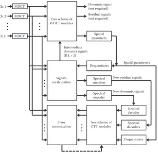
15.3.3 Basic Scheme of the Encoder
The suboptimal AbS optimization is performed based on the proposed MDCT-based closed-loop R-OTT module. The downmix and residual sig-nals, as well as the spatial parameters extracted from the closed-loop R-OTT module, are used as the initial input of the suboptimal AbS optimization. Practically, the AbS-SAC encoder is implemented, as shown in Figure 15.4. The audio signal in each channel is transformed to spectral coeficients by
391 Closed-Loop Spatial Audio Coding
means of MDCT. A tree scheme employing the closed-loop R-OTT modules is then performed in order to extract the spatial parameters. The new opti-mized downmix and residual signals are calculated based on the quantized spatial parameters. The downmix signal, as well as the residual signals, are then encoded by the spectral encoders, which actually consist of spectral coeficient quantization and the noiseless coding scheme. Prior to being sup-plied to the tree of OTT modules, all signals are decoded back by the spectral decoders. The decoded downmix and residual signals, as well as the quan-tized spatial parameters, are then used by the tree of OTT modules to upmix the audio signals. The error minimization block compares the spectral coef-icients of the reproduced audio signals with those of the original signals and then computes the errors.
A closed-loop optimization procedure, utilizing the error minimization block and the tree of OTT modules, can be carried out. The inputs of the optimization loop are the decoded spectral coeficients of the downmixed
MDCT
Block diagram of the AbS-SAC encoder.
392 Mixed-Signal Circuits
and residual signals, as well as the decoded spatial parameters. The purpose of the closed-loop approach is to examine all possible outcomes obtained by combining all quantization values of the spectral coeficient and spatial parameter quantizer in every possible way.
15.3.4 Suboptimal Algorithm
The operation of the algorithm can be explained as follows. For each index of the spectral coeficient, the candidates for suboptimal spectral coeficients of the downmix and residual signals are combined. Then, all resulting pos-sible combinations are examined to jointly choose a suboptimal coeficient, which provides the smallest error among the other tested coeficients, for the downmix signal, as well as a suboptimal coeficient for each residual signal. In performing this task, the tree of OTT modules takes the decoded spa-tial parameters, given by the dequantizer, as inputs. However, the process of selecting the suboptimal spatial parameters is not performed at this stage.
Note that this task has to be carefully completed by considering the Huffman encoding process. As explained previously (see Section 15.1.2), there is a case where all spectral coeficients within a group have zero values. For such a case there is no need to transmit the magnitude of the spectral coeficients. Modifying one or more spectral coeficients within that group causes the Huffman encoding process to be associated with another code-book. As a result, the spectral coeficients within the group need to be trans-mitted, which causes an increase in the transmitted bitrate. However, the error reduction achieved by modifying those spectral coeficients may not provide a worthy advantage, due to an increase in the transmitted bitrate.
For this reason, the search for the suboptimal spectral coeficients, par-ticularly downmix and residual signals, is not performed if the maximum absolute value of a group is zero. The process of choosing the suboptimal spectral coeficients is then followed by the selection of the suboptimal spa-tial parameters. For each parameter band, predetermined values of CLDs and ICCs are combined to form all possible combinations. A set of CLDs and ICCs is then selected as the suboptimal spatial parameters. At this stage, the downmix and the residual signal optimization is not performed.
The whole sequential process of searching for suboptimal signals and parameters is repeated as an iteration process. For the second and subse-quent iterations, the chosen suboptimal signals and parameters should be used as inputs of sequential process rather than the ones from the spectral decoder and the spatial dequantizer. The iteration process is terminated when error reduction below a given threshold has been reached. The qual-ity of the reconstructed audio is expected to improve with every iteration, however, the amount of improvement may reduce. Even if further iterations are executed the resultant values may not converge to the optimal values of both the spectral coeficients and the spatial parameters. Thus, the goal of this simpliied AbS algorithm is not to provide the optimal or near-optimal
393 Closed-Loop Spatial Audio Coding
signals and parameters. Instead, it is intended to provide a solution for impractical implementation of the full search AbS procedure while mini-mize the signal distortion.
The whole sequential process of searching for suboptimal signals and parameters is repeated as an iteration process. For the second and subse-quent iterations, the chosen suboptimal signals and parameters should be used as inputs of the sequential process rather than the ones from the spectral decoder and the spatial dequantizer. The iteration process is termi-nated when an error reduction below a given threshold has been reached. The quality of the reconstructed audio is expected to improve with every iteration, however, the amount of improvement may reduce. Even if further iterations are executed, the resultant values may not converge to the opti-mal values of both the spectral coeficients and the spatial parameters. Thus, the goal of this suboptimal algorithm is not to provide the optimal or near-optimal signals and parameters. Instead, it is intended to provide a solution for the practical implementation of the optimal searching procedure while minimizing the signal distortion.
15.3.5 Complexity of Sub-Optimal Algorithm
The proposed simpliied AbS algorithm is scalable, and its algorithmic com-plexity depends mainly on the number of loop procedures that have to be per-formed in inding the suboptimal spectral coeficients and spatial parameters, as well as the number of R-OTT modules whose signals and parameters are optimized. In order to reduce the complexity of the algorithm, the number of loop procedures and the involved R-OTT modules can be decreased. Based on equations from 15.7 through 15.14, for each spectral coeficient an R-OTT module performs a number of operations, Nott, consisting of 264 additions/
multiplications. Hence, the number of operations, Nop, for each index of
spec-tral coeficient required by the simpliied AbS algorithm can be determined as
Nop = Nott ×Nloop (15.20)
where Nott is the number of operations performed by an R-OTT module and
Nloop is the number of loop procedures need to be performed. As an
illus-tration, the number of loop procedures, Nloop, that have to be executed for
encoding ive-channel audio signals is given in Table 15.1.
15.4 Results
In order to evaluate the proposed system, a number of experiments designed to assess the encoding of 5 and 10 audio channels were conducted. The audio
394 Mixed-Signal Circuits
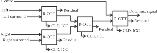
excerpts, sampled at 48 kHz, listed in Table 15.2 were prepared for the exper-iments. They were selectively chosen from a broad range of long sequence 5.1 audio signals ranging from speeches, pop, and classical music, as well as speciic sounds such as clapping hands. For each audio sequence, a lim-ited 12-s audio excerpt was selected based on the possibility of more tran-sient events. All of the 10-channel audio signals were produced by upmixing the ive-channel signals using a simple amplitude panning technique. The tree scheme of R-OTT modules for downmixing ive channels into a mono downmix, as given in Figure 15.5, was used in the experiments. However,
TABLE 15.1
Complexity of Simpliied AbS Algorithm
v Size of Predetermined Vector Number of Loops
0 1 0
1 3 243
2 5 3125
3 7 16,807
W Size of Predetermined Vector Number of Loops
0 1 0
1 3 6561
2 5 390,625
TABLE 15.2
List of Audio Excerpts for Experiments
Excerpt Name Description
Applause Clapping hands of hundreds of people
Drum Drum and male vocal with guitar as background Laughter Sound of hundreds of people laughing
Talk Male and female speech with music background Vivaldi Classical music with vocal
Centre
Left Residual
R-OTT
R-OTT R-OTT
R-OTT CLD, ICC
CLD, ICC
CLD, ICC Residual
Residual
Residual
Downmix signal
CLD, ICC Left surround
Right
Right surround
FIGURE 15.5
A tree scheme of R-OTT modules used in the experiments.
395 Closed-Loop Spatial Audio Coding
the low-frequency enhancement (LFE) channel was excluded for simplicity. Each channel of audio signals was segmented into 2048 time-domain sam-ples with 50% overlap. For calculating CLDs and ICCs 20 parameter bands were used. The 20 parameter bands for the MDCT-based R-OTT were deter-mined by mapping the 20 parameter bands of the CM-QMF to the 49 scale factor bands of the spectral coeficients. The downmix signal was encoded by AAC. The AAC multichannel codec, implemented as FAAC 1.28 and FAAD2 2.7, was used for benchmarking to demonstrate the usefulness of the proposed AbS-SAC approach, even though it is not the best implementation of the AAC standard.
15.4.1 Evaluation of Closed-Loop R-OTT Module
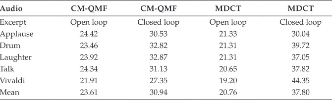
The evaluation of the closed-loop R-OTT module is aimed at demonstrating that the closed-loop approach can both improve the segSNR compared to the open-loop and perform much better in the MDCT domain. Table 15.3 shows the results of the experiment comparing segSNRs of ive-channel audio encoders employing open-loop and closed-loop R-OTT modules in both the CM-QMF-based and MDCT-based scenarios. All encoders operate at a bitrate of 160 kb/s per audio channel. Here all encoders are optimized to provide maximum segSNR performance.
The results show that the closed-loop R-OTT method improves average seg-SNR of all the tested audio excerpts. It clearly indicates that the closed-loop R-OTT method is capable of minimizing signal distortion, resulting in seg-SNR improvement. Furthermore, the MDCT-based closed-loop R-OTT mod-ule outperforms, in terms of segSNR, the CM-QMF-based closed-loop R-OTT module for all tested audio excerpts other than Applause. For this Applause audio excerpt, both CM-QMF and MDCT schemes are competitive. It is an indication that the closed-loop R-OTT module generally performs better in the MDCT domain when compared with the CM-QMF domain. Moreover, the results also show that the open-loop R-OTT module has smaller segSNRs in the MDCT domain rather than in the CM-QMF domain. As expected, it indicates that the open-loop R-OTT module is basically not an appropriate
TABLE 15.3
SegSNRs (dB) of Open- and Closed-Loop R-OTT Modules
Audio CM-QMF CM-QMF MDCT MDCT
Excerpt Open loop Closed loop Open loop Closed loop
Applause 24.42 30.53 21.33 30.04
Drum 23.46 32.82 21.31 39.72
Laughter 23.92 32.87 21.31 37.05
Talk 24.34 31.13 20.65 37.82
Vivaldi 21.91 27.35 19.20 44.35
Mean 23.61 30.94 20.76 37.80
396 Mixed-Signal Circuits
method to be applied in the MDCT domain. However, employing a closed-loop approach indicates that a signiicant improvement is achieved, even better than the CM-QMF-based method.
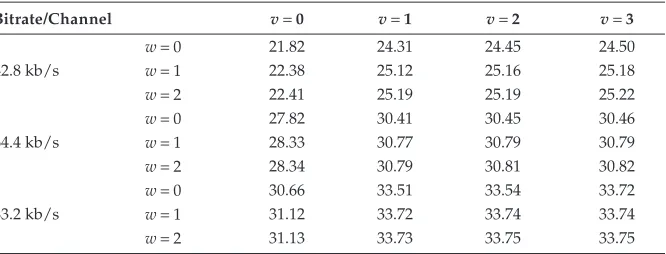
15.4.2 Evaluation of Sub-Optimal Algorithm
The performance of the suboptimal algorithm is assessed by investigating the SNR of the reconstructed audio signals against the complexity of the algorithm. The suboptimal algorithm is tested for various computational complexities by assigning v= 0, 1, 2, 3 and w= 0, 1, 2. Assigning v= 0 and w= 0 means that the suboptimal algorithm is not performed. Moreover, v= 0
and w≠ 0 means that the suboptimal algorithm chooses the suboptimal
spa-tial parameter but does not ind the suboptimal spectral coeficients of the downmix and residual signals. On the other hand, deining v≠ 0 and w= 0
instructs the algorithm to select the suboptimal spectral coeficients without selecting suboptimal spatial parameters. The algorithm is terminated when the segSNR improvement is less than 10−4. The average segSNRs achieved by
the AbS-SAC, operating at three different bitrates, 42.8, 65.4, and 83.2 kb/s per audio channel, are given in Table 15.4.
As can be seen, the encoder employing suboptimal algorithm (i.e., v≠ 0 and w≠ 0), for various values of v and w, can improve the segSNR although the
improvement is different for each complexity level. The results suggest that the best coniguration to perform the proposed suboptimal algorithm, in terms of the segSNR improvement with the least complexity, is achieved by setting v= 1
and w= 1. However, to lower the complexity to a more reasonable level one can
set v= 1 and w= 0 and still achieve considerable segSNR improvement. 15.4.3 Objective Evaluation
The goal of this experiments is to objectively assess perceptual quality of the proposed AbS-SAC for various operating bitrates. To our knowledge, no
TABLE 15.4
Average SegSNRs (dB) for Various Complexity Levels
Bitrate/Channel v= 0 v= 1 v= 2 v= 3
w = 0 21.82 24.31 24.45 24.50
42.8 kb/s w = 1 22.38 25.12 25.16 25.18
w = 2 22.41 25.19 25.19 25.22
w = 0 27.82 30.41 30.45 30.46
64.4 kb/s w = 1 28.33 30.77 30.79 30.79
w = 2 28.34 30.79 30.81 30.82
w = 0 30.66 33.51 33.54 33.72
83.2 kb/s w = 1 31.12 33.72 33.74 33.74
w = 2 31.13 33.73 33.75 33.75
397 Closed-Loop Spatial Audio Coding
objective perceptual test is currently available for high-quality multichan-nel audio signals. Thus, we have adapted the perceptual evaluation of audio quality (PEAQ), an ITU-R BS.1387-1 recommendation for assessing a mono audio signal, and currently under standardization process to include mul-tichannel audio assessment, for evaluating mulmul-tichannel audio signals. The objective difference grade (ODG), that has ive grades: 0 (imperceptible), −1
(perceptible but not annoying), −2 (slightly annoying), −3 (annoying), and −4
(very annoying), was irst measured for each channel of audio signal. The average values of the ODG scores over all channels are then presented as the inal results for multichannel audio. A software developed by McGill University is used for calculating ODG score. Moreover, the experiments also include encoding of 10-channel audio signals. This is intended to show that, for larger channels at the given bitrate per audio channel, the perfor-mance improvement is even higher. Considering the complexity of the AbS-SAC encoder, for encoding 5 audio channels, the suboptimal algorithm is assigned with v= 1 and w= 1 while, for encoding 10 audio channels,
param-eters are set to v= 1 and w= 0.
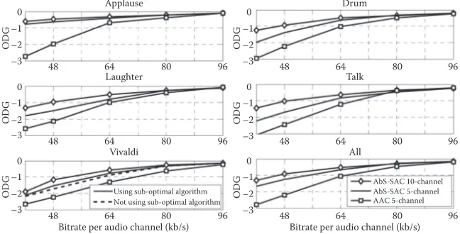
The results of the experiments for encoding 5-channel and 10-channel audio signals are given in Figure 15.6. For simplicity, the results of AAC 10-channel are not shown, as they are almost identical to those achieved on AAC 5-channel. The overall ODG, averaged over all audio excerpts as shown in the lowest right plot, shows that the AbS-SAC, applied to both 5 and 10 channels, signiicantly outperforms, in terms of PEAQ, the tested AAC multichannel for all operating bitrates from 40 to 96 kb/s per audio
0
Bitrate per audio channel (kb/s)
Using sub-optimal algorithm
Bitrate per audio channel (kb/s)
AbS-SAC 10-channel AbS-SAC 5-channel AAC 5-channel
80 96
FIGURE 15.6
Objective difference grade (ODG) of the AbS-SAC for various bitrates in comparison with the tested AAC multichannel. The ODG scores of the tested AAC multichannel, for encoding 10-channel audio signals, are not plotted as they are similar to the ODG scores of the tested AAC multichannel for encoding 5-channel audio signals.
398 Mixed-Signal Circuits
channel. However, the performance increase is greater when encoding 10 channels. It can be seen that an improvement of more than 2 points of ODG grade is achieved on the Applause audio excerpt at a bitrate of 40 kb/s per audio channel. Moreover, up to 1 point of ODG improvement is achieved on every tested audio excerpt. The results indicate that the proposed AbS-SAC technique signiicantly improves encoding performance for a wide range of tested audio materials.
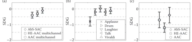
15.4.4 Subjective Evaluation
The proposed AbS-SAC approach, for encoding ive-channel audio signals, has also been evaluated using listening tests. The subjective assessment of small impairments in the audio system, as recommended in the ITU-R BS.1116-1 using the “double-blind triple stimulus with a hidden reference” method, is used. The subjective difference grade (SDG), having ive grades that are similar to ODG, is used. Three codecs were taken under test: AbS-SAC, AAC multichannel, and HE-AAC multichannel. In order to reduce the dificulty, that the listeners would experience in scoring the tested audio excerpts because of too small impairment, a low but still realistic bitrate should be chosen. In the experiments, a bitrate of 51.2 kb/s per audio chan-nel, equal to an overall ive-channel bitrates of 256 kb/s, is chosen for both the SAC and AAC multichannel. Below this bitrate, the proposed AbS-SAC cannot provide a signiicant segSNR improvement. On the other hand, operating both coders above the chosen bitrate would increase the dificulty for the listeners in assessing the tested audio excerpts. In addition, it is still in the range of the normal operation bitrates of the AAC multichannel which is used as a benchmark. Moreover, the HE-AAC multichannel operates at its maximum typical bitrate of 32 kb/s per audio channel, which is equal to 160 kb/s for all ive audio channels. Operating the HE-AAC above this bitrate is not useful in terms of coding eficiency, which means that the HE-AAC multichannel may not achieve a better performance.
A total of 20 listeners participated in this listening test. As speciied in the expertise of the listeners are evaluated by averaging their SDG scores over all audio excerpts. Based on this average SDG score, a postscreening method was applied. Three listeners with an average SDG score greater than zero are assumed to be unable to correctly distinguish between the hidden reference and the tested audio object. Thus, the data from those three listeners was discarded. Only the SDG scores from the other 17 listeners were used for the results.
Figure 15.7a presents the average SDG score of each tested audio codec averaged over all audio excerpts. The error bars show the 95% conidence intervals of the mean scores. The results show that the SDG scores of all the tested codecs are competitive and very close to a grade of imperceptible. However, the proposed AbS-SAC approach achieves the highest SDG score. Furthermore, Figure 15.7b shows the SDG score of every tested audio excerpt
399 Closed-Loop Spatial Audio Coding
averaged over all tested audio codecs, where the Applause audio excerpt has the lowest SDG score. As expected, it suggests that the Applause audio excerpt is the most critical item among the tested audio excerpts. For this Applause audio excerpt the proposed AbS-SAC approach also achieves the highest SDG score as shown in Figure 15.7c.
15.4.5 Complexity Assessment
In order to assess the performance of the suboptimal algorithm with regards to complexity, the bottom-left graph in Figure 15.6 shows the ODGs of two variants of the proposed AbS-SAC technique, with two extremely different complexity scales, for encoding ive channels of the Vivaldi audio excerpt. The irst one is the AbS-SAC codec using the suboptimal algorithm where
v= 1 and w= 0 and all spectral coeficients at every OTT module are
opti-mized, and the other does not use the suboptimal algorithm. The results clearly demonstrate that without the suboptimal algorithm the proposed codec is still able to achieve signiicant quality improvement while the sub-optimal algorithm improves the performance further.
15.5 Conclusions
This chapter proposes a new AbS-SAC technique where the AbS concept is applied when choosing the suboptimal downmix signal and the spatial parameters so as to minimize the encoded signal distortion. It is demon-strated that the closed-loop R-OTT algorithm signiicantly reduces the error introduced by the spatial parameter quantization process resulting in sig-niicant segSNR improvement. In addition, it is shown that the frequency domain parameterization is more suitable for the AbS-SAC method instead of the sub-band domain as applied in MPS for encoding error reduction.
0
The results of the subjective test, to compare performance of the proposed AbS-SAC, AAC mul-tichannel, and HE-AAC multichannel: (a) SDG scores of the tested audio codecs averaged over all audio excerpts, (b) SDG scores of all audio excerpts averaged over the tested audio codecs, (c) SDG scores of the tested audio codec for the applause audio excerpt.
400 Mixed-Signal Circuits
Additionally, the MDCT allows simpliication of the coding structure by removing the transformation of the residual signals from the sub-band domain to spectral coeficients of the MDCT for the purpose of quantization. Moreover, a simpliied AbS-SAC search algorithm has also demonstrated its ability to ind suboptimal signals and parameters with signiicantly lower complexity to address the practicality of implementation of the optimal searching procedure. Subjective tests show that the AbS-SAC method out-performs, in terms of SDG score, the tested AAC multichannel, at a bitrate of 51.2 kb/s per audio channel. In addition, the AbS-SAC method has con-sistently higher PEAQ ODG scores than the tested AAC multichannel, for bitrates ranging from 40 to 96 kb/s per audio channel.
References
1. Brandenburg, K., Faller, C., Herre, J., Johnston, J. D., Kleijn, W. B. Perceptual coding of high-quality digital audio. Proc. of the IEEE, 101(9), 1905–1919, 2014. 2. Herre, J., Dietz, M. MPEG-4 high-eficiency AAC coding. IEEE Signal Process.
Mag., 25(3), 137–142, 2008.
3. Baumgarte, F., Faller, C. Binaural cue coding—Part I: Psychoacoustic funda-mentals and design principles. IEEE Trans. Speech, Audio, Lang. Process., 11(6), 509–519, 2003.
4. Moon, H. A low-complexity design for an MP3 multichannel audio decoding system. IEEE Trans. Speech, Audio, Lang. Process., 20(1) 314–321, 2012.
5. Breebaart, J. van de Par, S., Kohlrausch, A. Schuijers, E. Parametric coding of stereo audio EURASIP J. Appl. Signal Process., 2005, 1305–1322, 2005.
6. Hilpert, J., Disch, S. The MPEG surround audio coding standard [Standards in a nutshell]. IEEE Signal Process. Mag., 26(1) 148–152, 2009.
7. Herre, J., Kjorlings, K., Breebaart, J., Faller, C., Disch, S., Purnhagen, H., Koppens, J. et al. MPEG Surround—The ISO/MPEG standard for eficient and compatible multichannel audio coding. J. Audio Eng.Soc., 56(11), 932–955, 2008.
8. Kondoz, A. Digital Speech: Coding for Low Bit Rate Communication Systems. London: John Wiley Ltd, 2004.
9. Elitri, I., Gunel, B., Kondoz, A. Multichannel audio coding based on analysis by synthesis. Proceedings of the IEEE, 99(4), 657–670, 2011.
10. Breebaart, J., Hotho, G., Koppens, J., Schuijers, E., Oomen, W., de Par, S. V. Background, concepts, and architecture for the recent MPEG Surround stan-dard on multichannel audio compression. J. Audio Eng. Soc.,55(5), 331–351, 2007.
Q3