A NOVEL PROPOSAL OF GAOFEN-3 SATELLITE CONSTELLATION FOR
MULTI-APPLICATIONS
Xiaolan Qiu a,b,c, Chibiao Ding a,b,c*, Bin Lei a,c, Bing Han a,c, Fangfang Li a,c
a Key laboratory of Geo-spatial Information Processing and Application System, Chinese Academy of Sciences, Beijing, China b Institute of Electronics, Chinese Academy of Sciences, Suzhou Research Center, Suzhou, China
c Institute of Electronics, Chinese Academy of Sciences, Beijing, China
(xlqiu, cbding, leibin, han_bing, ffli1)@mail.ie.ac.cn
Commission I, WG I/3
KEY WORDS: Satellite constellation, Gaofen-3, SAR, Multi-applications, InSAR
ABSTRACT:
Gaofen-3 is the first C-band fully polarimetric SAR satellite in China, which is widely used in various fields such as ocean monitoring, disaster reduction and so on. In this paper, a new satellite constellation is proposed based on the orbit of Gaofen-3 satellite. The constellation includes Gaofen-3 and other two duplicates. It is able to do repeat-pass interferometry, repeat-pass differential interferometry, along-track interferometry and stereo measurement. With these abilities, it can generate the earth DEM without ground control points and have better performance in moving target identification and monitoring. The performance and the system requirements are analysed, which provides a good reference for the design of spaceborne SAR constellation.
* Corresponding author
1. INTRODUCTION
Gaofen-3 is the first C band fully polarimetric SAR satellite in China. It can work in twelve different modes, in which the highest resolution reaches 1 meter. It also is the first Chinese dual-channel spaceborne SAR, which has the ability of along-track interferometry. Gaofen-3 was launched in August 2016, and was officially put into operation in January 2017. Now Gaofen-3 is widely used in various fields such as ocean monitoring, disaster reduction, water conservancy and so on. However, single low-orbit SAR satellite observation has its limitations, such as a long revisit cycle, bad performance in low or high speed moving target monitoring. So, a number of SAR constellations are proposed and established. For example, the Sentinel-1 A/B constellation (Ramón Torres, 2016), the COSMO-SkyMed constellation (D. O. Nitti, 2009) and the proposed RADARSAT Constellation Mission (RCM) (Sergey Samsonov, 2016), which all aim at a shorter revisit period, so the satellites in each constellation are in the same orbit with different true anomalies. The SAR-lupe constellation, which has three different orbits, can achieve both a short revisit period and different observation directions. The Tandem-X constellation (Manfred Zink, 2016) has a HELIX satellite formation, which aims at high-quality interferometry to get high-quality DEM. Besides, it is able to do SAR-GMTI with the along-track baseline (Stefan. V, 2011). Moreover, the interferometric Cartwheel (R. Fjortoft, 2004) and the BISSAT mission (A. Moccia, 2002) are proposed, which have bistatic SAR imaging mode. However, all these constellations above are some kind of single-functional in our opinion. Except for the bistatic SAR constellations, the cooperation of the satellites in a constellation is not very close.
In this paper, a new multi- functional constellation is proposed based on the Gaofen-3 orbit. The main orbital elements are given and the orbits are demonstrated. Furthermore, the work modes and the multi-applications are analysed and simulated. Also, the requirements about the SAR systems to fulfill these
applications are given, which provides a good reference for spaceborne SAR constellation design.
2. DESIGN OF THE GAOFEN-3 CONSTELLATION
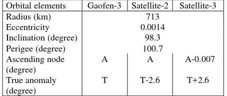
The Gaofen-3 satellite flies in a sun-synchronous orbit. The orbit radius is about 710 km and the inclination is about 98 degrees. With such an orbit, the satellite revisit period is about 29 days. In order to make an extension of the observation ability of Gaofen-3, a constellation including Gaofen-3 and other two duplicates is designed. The following table shows the orbit difference between Gaofen-3 and the other two satellites. In this constellation, satellite-2 flies in the same orbit of Gaofen-3, with about 2.6 degree true anomaly departure, which takes about 44.8 seconds for satellite-2 to fly to the same position as Gaofen-3 in the earth coordination. Satellite-3 flies in an orbit close to the Gaofen-3 orbit, with a 0.007 degree ascending node difference and 2.6 degree true anomaly difference. Satellite-3 keeps ahead of Gaofen-3, the along-track baseline is about 326 km while the cross-track baseline is about 500 m. According to Gaofen-3 repeat-pass InSAR processing results, a 500 m cross-track baseline can guarantee good coherence, the coherent coefficient is around 0.8 and can reach 0.88 in some cases (Tao Zhang, 2017).
Orbital elements Gaofen-3 Satellite-2 Satellite-3
Radius (km) 713
Eccentricity 0.0014
Inclination (degree) 98.3
Perigee (degree) 100.7
Ascending node (degree)
A A A-0.007
True anomaly (degree)
T T-2.6 T+2.6
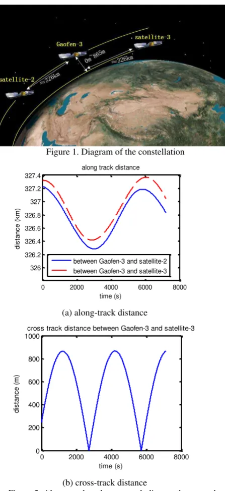
Figure 1 illustrates the constellation. The differences of the orbits are enlarged to show the geometry. The cross and along track distance of the satellites are calculated and drawn in Figure 2, where the cross track distance between Gaofen-3 and satellite-3 varies from zero to 865 m.
Figure 1. Diagram of the constellation
0 2000 4000 6000 8000
cross track distance between Gaofen-3 and satellite-3
time (s)
Figure 2. Along-track and cross-track distance between the satellites
3. WORKING MODES AND ABILITIES OF THE CONSTELLATION
Based on the above designed constellation, four typical working modes are proposed for different applications, which are described as follows.
3.1 Stereo and InSAR mode
Stereo and InSAR mode aims to get the high-quality DEM without ground control points. The imaging geometries of the three satellites are shown in Figure 3.
Figure 3. Stereo and InSAR working mode illustration
In this mode, Gaofen-3 and satellite-3 work in non-squint case, where the Doppler centroid is close to zero. With a cross baseline about 500 m and a time interval about 45 s, the image pairs can get good coherence, providing the phase stability and consistency were guaranteed by the two SAR systems. Satellite-2 works in squint case by controlling the SAR antenna to look forward or backward. Then satellite-2 and Gaofen-3 can form stereo SAR image pairs. As designed in this constellation, the along-track distance is about 326 km, so the intersection angle between scenario to satellite-2 and scenario to Gaofen-3 can be about20 . To avoid interference and ambiguity between the signals of the two satellites, the simultaneous imaging areas will keep a reasonable distance. So it is better for satellite-2 to look backward. Simulation shows that, if satellite-2 looks forward and we hope to guarantee a 10 s observation interval between Gaofen-3 and satellite-2 for a selected scene, and the intersection angle can be about15 , which can still guarantee a good performance of stereo measurement as analysed in the following.
For stereo SAR, the 3-D location of each matched pixel can be calculated by the following equations,
1 1 1 1 1 1
Gaofen-3 and satellite-2, respectively.
1
R and R2 are the slant ranges measured for this target in
both images.
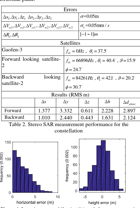
For Gaofen-3, a dual frequency GPS receiver is used, and after kinematic processing, a 3-D position accuracy of 5 cm and velocity accuracy of 0.05 mm/s is achieved as reported by Chibiao Ding (2017). The slant range error caused by the system is within 0.3m (Chibiao Ding, 2017) and the slant range error by the atmosphere after correction is about 1m which can be further improved according to the meteorological information (Michael Eineder, 2011). resulted location error. Then, the 3-D location performance for stereo measurement is analysed by Monte-Carlo experiments, and the results can be found in Table 2 and Figure 4. Here is
Table 2. Stereo SAR measurement performance for the constellation
Figure 4. Location error while 15.9 and slant range error is 1m
It can be seen that, the stereo measurements can get a height precision about 2.2m when 15.9 and the slant range error is 1m. And when 20.2 , the height error is then about 1.6 m. This means the stereo measurement can provide lots of control points for Gaofen-3 and satellite-3 to do the InSAR calibration and DEM generation work. Though, the precision for one single control point is not very high, the number of the control points can be large, which can also provide qualified DEM.
3.2 InSAR and DInSAR mode
InSAR and DInSAR mode aims to generate the DEM combined with the deformation information, so that some disasters, such as landslides, can be monitored.
Figure 5. InSAR and DInSAR working mode illustration
In this mode, all three SAR satellites work in the non-squint case. Gaofen-3 and satellite-3 get the cross-track InSAR image pairs. Satellite-2 and Gaofen-3 form the repeat pass DInSAR configuration. With the DEM provided by Gaofen-3 and satellite-3, the differential phase caused by deformation can be extracted more precisely.
3.3 Multi-angle observation mode
The multi-angle observation mode aims to get more comprehensive information about the observed scenario. For the mountain area, the shadow can be decreased, and for the city area, the outlines of the buildings can be more complete.
Figure 6. Multi-angle observation illustration
In this mode, Gaofen-3 still works in the non-squint case, as its antenna is not able to scan in azimuth. The satellite-2 and satellite-3 should have the azimuth scanning ability and work in forward- and backward- looking configuration. Then the constellation can obtain three different observation angles each time. Together with the left and right looking ability in ascending and descending orbit, it can obtain six different observing angles for each scenario. With these different observations, target detection and recognition task will have more supports, and multi-direction stereo measurement can be done to get better results.
3.4 Moving target monitoring mode
Figure 7. Moving target monitoring mode illustration
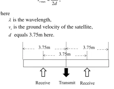
In this mode, each SAR works in the dual-receiving channel (DRC) mode, while Gaofen-3 is side-looking, satellite-2 and satellite-3 are forward-looking and backward-looking. The SAR antenna of Gaofen-3 is 7.5m in azimuth direction as shown in Figure 8. While working in the DRC mode, the receive centers have a distance of 3.75 m. With such an along-track baseline, the maximum unambiguous radial velocity vrmax can be calculated by the following equation
max
v is the ground velocity of the satellite,
d equals 3.75m here.
Figure 8. Illustration of the Gaofen-3 DRC mode
So vrmax is about 48 m/s, which is quite a high speed and is almost enough for most of the ground and ocean moving targets. However, the along-track interference for a single SAR only can get the radial velocity. We do not know the true moving direction and the true velocity amplitude. In this constellation, the true velocity of moving targets can be estimated by two or three satellites (Paco Lopez-Dekker, 2014). Because satellite-2 and satellite-3 can get their radial velocities, while the radial directions are different from Gaofen-3. The relationship between the true velocity vector and the radial velocities is shown in Figure 9. Then the velocity amplitude vreal and the
direction angle vcan be solved by the following equations
cos cos( )
Figure 9 Illustration of the relationship between the true velocity and the radial velocity of a moving target
As to the minimum detectable velocity and the precision of the velocity estimation, it can be estimated by the following estimation is limited to this level.
Because the moving target will appear at different position in each SAR image of the image sequence, the velocity also can be confirmed by this information. The time interval of these images can be more than 10 s, and the target differential position extraction precision is on the resolution level, so the velocity estimated using the image sequence can reach a better precision on the decimetre per second level. As a result, the constellation can do the moving target identification work using the DRC mode on-board each satellite, and then estimate the true velocities of moving targets from the image sequence, so as to get better performance in moving target monitoring.
4. CONCLUSION
In this paper, a new multi-application SAR constellation is proposed. The designed constellation can do stereo measurement combined with InSAR and DInSAR, and is able to monitor the moving targets and get their velocity with amplitude and direction. The orbits and the collaboration working modes for the constellation are designed, concerning the Chinese Gaofen-3 satellite. Furthermore, the performances, such as stereo SAR measurement, are analysed theoretically and by simulations. This constellation concept and the performance analysis results provide good references for SAR constellation design of multi-applications.
ACKNOWLEDGEMENTS
REFERENCES
Ramón Torres, et al, 2016, Sentinel-1B LEOP and commissioning, In 2016 IEEE International Geoscience and Remote Sensing Symposium (IGARSS), Beijing, China, pp. 3877 – 3881
D. O. Nitti, et al, 2009, Quantitative analysis of stripmap and spotlight SAR interferometry with COSMO-SkyMed constellation, In 2009 IEEE International Geoscience and Remote Sensing Symposium, pp. II-925 - II-928
Sergey Samsonov, et al, 2016, RADARSAT constellation mission for monitoring ground deformation in Alberta's oil sands, In 2016 IEEE 17th Annual Wireless and Microwave Technology Conference (WAMICON), pp. 1-4
Manfred Zink, et al, 2016, TanDEM-X mission status: The complete new topography of the Earth, In IEEE International Geoscience and Remote Sensing Symposium (IGARSS), Beijing, China, pp. 317 – 320
Stefan V, et al, 2011, Large along-track baseline SAR-GMTI: First results with the TerraSAR-X/TanDEM-X satellite constellation, In 2011 IEEE International Geoscience and Remote Sensing Symposium, pp.1319-1322
R. Fjortoft, et al, 2004, Impact of ambiguities in multistatic SAR: some specificities of an L-band interferometric cartwheel, In 2004 IEEE International Geoscience and Remote Sensing Symposium, pp 1754 – 1757
A. Moccia, et al, 2002, BISSAT: a bistatic SAR for Earth observation, In IEEE International Geoscience and Remote Sensing Symposium, pp. 2628-2630
Paco Lopez-Dekker, et al, 2014, Experimental Bidirectional SAR ATI acquisitions of the ocean surface with TanDEM-X, In 10th European Conference on Synthetic Aperture Radar, pp.1-4
Chibiao Ding, et al, 2017, Preliminary Exploration of Systematic Geolocation Accuracy of GF-3 SAR Satellite System, Journal of Radars, 2017. 6 (1), pp.11-16.
Tao Zhang, et al, 2017, Repeat-pass SAR Interferometry Experiments with Gaofen-3: A Case Study of Ningbo Area, http://lanl.arxiv.org/abs/1704.01067