3D MODELING FROM GNOMONIC PROJECTIONS
L. Barazzetti (1), M. Previtali (1), M. Scaioni (2)
(1) Politecnico di Milano, Department of Building Environment Science and Technology Via M. d’Oggiono, 18/a, 23900 Lecco, Italy
email: [email protected], [email protected] - web: http://www.icet-rilevamento.lecco.polimi.it/ (2) Tongji University, Department of Surveying and Geo-Informatics
1239 Siping Road, 200092 Shanghai, P.R. China - email: [email protected]
Commission III
KEY WORDS: Gnomonic Projection, Matching, Orientation, Robust Estimation
ABSTRACT:
The paper presents a strategy able to derive and process high resolution images created by means of gnomonic projections. The implemented pipeline can be split into two phases: first, the sensor resolution of the camera is physically increased by acquiring and merging a set of images with a rotating camera equipped with a long focal lens; then the new set of gnomonic projections is processed with a 3D reconstruction methodology able to deal with very large images. Several issues are addressed in the paper, starting from image acquisition up to 3D modelling. Gnomonic projections have been demonstrated to be powerful tools when traditional pinhole images do not allow the reconstruction of small and fine details. Examples and comparisons aimed at determining the correctness of the mathematical approach for image orientation are illustrated as well.
1. INTRODUCTION
The chance to obtain accurate and detailed 3D models of close-range and architectural objects from image-based processing has been widely demonstrated over the last years. Nowadays all traditional photogrammetric and computer vision tasks can be carried out in an automatic way: camera calibration, image orientation, and 3D surface reconstruction through dense image matching. Very often existing methods integrate traditional techniques of both photogrammetry and computer vision (Barazzetti et al., 2011). The result is that today these solutions can compete with close-range 3D scanners, usually more expensive and cumbersome although simpler to be used at the data acquisition stage.
On the other hand, some problems related to the physical characteristics of imaging sensors need to be addressed. Modern CCD and CMOS sensors capture images with geometric resolution superior to 20 Mpx and radiometric resolution higher than 16 bits. The level of detail of a 3D modelling project strictly depends on the ground sample distance (GSD). The reconstruction of fine details needs the acquisition of ad-hoc datasets of images where all small parts must be clearly visible. This can be usually achieved by reducing the camera-object distance and then by increasing the total number of images to be processed.
Another solution is instead based on Super Resolution (SR), which can be intended as a procedure which increases image resolution (Milanfar, 2010). One possible way is a reduction of the pixel size (preserving the metric sensor size), which however tends to worsen the signal-to-noise ratio. Alternatively, the chip-size could be increased but capacitance increases and storage problems arise.
Another method is based on the use of a set of low resolution (LR) images that are then merged to obtain a SR mosaic. The main idea is the acquisition of images with sub-pixel shifts and a following data processing system capable of fusing all the different information. In the literature, there is an impressive number of papers dealing with this topic (some examples are Bascle at al., 1996; Berthod et al., 1994;
Dellaert at al, 1998; Elad and Feuer, 1999; Irani et al., 1992; Numnonda et al., 1993, Shekarforoush et al., 1996). The workflow is often quite similar: after a preliminary image alignment, images are combined to extract a ‘sharp’ image with a superior resolution. In some cases, shifts can be replaced by a series of multi-focus data (Elad and Feuer, 1997), where multiple shots with different focus points can be acquired and merged to obtain a sharp image.
The key concept is a subdivision of source images into decompositions that are then integrated to obtain a composite reconstruction. Then the sharp image is created with an inverse multi-resolution transform.
One of the most remarkable advantage of these methods regards the opportunity to use standard cameras with a consequent reduction of costs. Standard applications are the ones in the medical domain, microscopy, micro-mineralogy, macro-photography, and satellite images, among the others. In this paper we present an alternative solution (encapsulated now in a complete data processing pipeline) where the actual camera’s sensor size is virtually increased by using long focal lenses coupled with the gnomonic projection to fuse standard pinhole images.
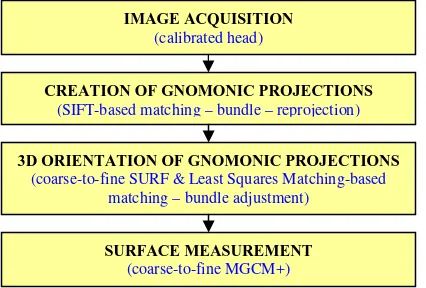
Shown in Figure 1 is a synthetic flowchart. Starting from the intuition of Kauhanen et. al (2009), the metric pixel size and focal length of original images can be transferred to the final mosaic, whereas sensor size is increased as a function of the field of view covered during image acquisition. In addition, the geometric barrel or cushion distortion of the new virtual sensor is also removed for further matching and surface reconstruction purposes.
After the automatic creation of several gnomonic projections with a variable sensor size, an automated methodology for image orientation was implemented to handle imagery with very large image resolution, preserving original data with a multi-resolution matching approach.
Fig. 1. The flowchart for images acquisition and 3D reconstruction from gnomonic projections.
In the current implementation a modified release of Multi-photo Geometrically Constrained Matching (MGCM+) algorithm was used (Previtali et al., 2011). At the end, surface can by meshed and textured.
The experiments carried out showed a sub-pixel precision during bundle adjustment, proving the correctness of the adopted gnomonic camera model. The advantages of the method will be demonstrated by the products that can be created by using only a limited number of high resolution gnomonic projections; these include 3D models, DEMs, orthophotos and true-orthophotos. The method allowed the creation of synthetic cameras with sensor size twice or three times as much as standard matrix sensors, which however is not the physical limit of the method. Indeed, the method could provide gigapixel images for very long telephoto lenses, although memory issues arise and increase CPU time.
2. THE METHOD
2.1 Generation of high resolution images through gnomonic projections
Multiple images taken with a rotating camera can be registered and stitched within a homographic transformation:
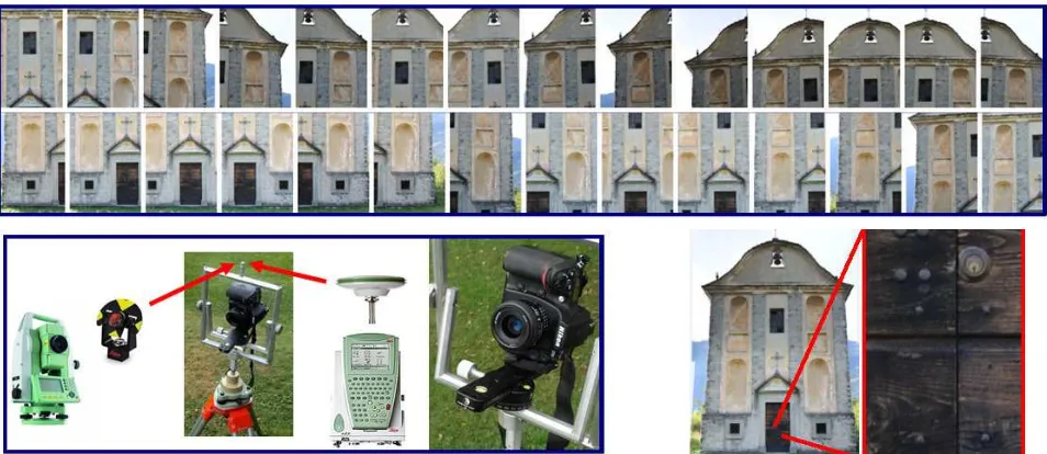
1 different camera attitudes), parallax errors can be removed from the dataset. In addition, the perspective centre is aligned with a pole on top of the head. Here, a prism or a GNSS receiver can be placed in order to geo-reference the survey into a geodetic reference system (see Fig. 3). The coordinates are measured with these external sensors (theodolite or GNSS) to give the location of the perspective centre of the final gnomonic projection. The vertical shift between the pole and the camera can be easily estimated with a calibration project, and can be therefore assumed as being constant for all images. These 3D coordinates will be directly used as pseudo-observations (see next Section) in bundle adjustment in order to control block deformations.
In general, a projection is a mapping of the Earth onto a flat surface. Here, the scene around the camera represents the globe. Gnomonic projections are obtained by projecting the point on the globe onto a plane tangent to the sphere (Fig. 2). The equations for a projection with central latitude 0 and first applied to reduce the intensity difference between overlapping images (Uyttendaele et al., 2001). Secondly, a
multi-blending algorithm (Burt and Adelson, 1983) removes the remaining image edges avoiding blurring of high operator). All descriptors are compared with a kd-tree search in O(nlog n) time.
Finally, the matched image points allow the estimation of the unknown parameters within a bundle adjustment based on the Levenberg-Marquardt algorithm (Brown and Lowe, 2007). Images can then be mapped with a gnomonic projection to obtain a high resolution mosaic. Image distortion can be removed beforehand from original data with a proper calibration project (Remondino and Fraser, 2006).
Fig. 2. Generation of a gnomonic projection, i.e. a non conformal mapping where great circles are mapped to straight lines. It replicates the effect of image acquisition by means of spherical lenses.
CREATION OF GNOMONIC PROJECTIONS
(SIFT-based matching – bundle – reprojection)
3D ORIENTATION OF GNOMONIC PROJECTIONS
(coarse-to-fine SURF & Least Squares Matching-based matching – bundle adjustment)
IMAGE ACQUISITION
(calibrated head)
SURFACE MEASUREMENT
The final mosaic is a (distortion-free) gnomonic projection with a focal length equal to that of the original images. The sensor is virtually increased (in this case the final mosaic is 6512×8900 pix) but pixel size is preserved. In a few words, if the original sensor size was 36 mm ×23.9 mm, the new projection is virtually acquired with a camera with a sensor of about 54.7 mm × 74.76 mm.
2.2 Processing of multiple gnomonic projections
As previously mentioned, the 3D reconstruction pipeline is based on a block of gnomonic projections virtually acquired with different sensors. However, the focal length and pixel size of each projection are constant, whereas radial and tangential distortions can be compensated for during the generation of the mosaic. If radial and tangential distortions are modelled, the principal point is the centre of the projection. This means that calibration parameters can be automatically fixed by looking at the size (in pixel) of each new projection and the metric pixel size of single pinhole shots.
Obviously, the reader might ask why original images are not used for data processing, as they are standard pinhole imagery and 3D reconstruction can be achieved with the normal procedures reported in the literature. First of all, a gnomonic projection can be crated from images that have a limited overlap (at least between 2 images), while image orientation requires points matched on multiple shots (at least 3 images). Therefore, the use of a single image from a set of many improves the robustness of image orientation and reduces the global number of views. Then, according to authors’ experience, if many images have the same perspective centre, convergence problems might arise during a standard photogrammetric bundle block adjustment (exception made for bundle implementations which consider an appropriate set of initial values). However, it could be difficult to generate these initial approximations for image blocks having complex configurations. Finally, as demonstrated by Stamatopoulos and Fraser (2011), the standard collinearity principle is not always appropriate if long focal length lenses (field of view less than 10°) are
employed. Here, although images are acquired with telephoto lenses, the final projection is virtually acquired with a normal lens when compared to the new sensor size.
An example of 3D processing is the main façade of the church shown in Figures 3 and 4, which was reconstructed from a set of 5 SR images only. One of the main problems of data processing is the final image size, which makes coarse-to-fine approaches indispensable. SURF operator and robust estimators are initially run to detect a set of corresponding points on sub-sampled images (generally 25% of the original size), then Least Squares Matching (LSM) allows a refinement on full resolution images (Baltsavias, 1991). A free-network bundle adjustment (Granshaw, 1980) is used to recover camera poses (Fig. 4), obtaining an estimated sigma-naught of about 0.6 pixels. This value confirms the correctness of the mathematical model for image orientation, although more details are given in the following Section. Finally, the surface of the object can be reconstructed with the dense multi-photo matcher proposed in Previtali et al. (2011). This allows one to deal with SR images (at their original size) and provided the results shown in Figure 4, which consist in a high resolution textured 3D model. Metric rectification is a very common product for this category of objects and can be easily achieved by using the central projection taken in front of the façade. In this case, the photogrammetric project provided a set of image-to-object points for the estimation of the rectifying homography. It is interesting that the direct use of sets of parallel and perpendicular lines is a mistake for the considered church: elements like pillars or beams are not completely vertical or horizontal (this effect is not clearly visible with a simple visual inspection). Results are visible in Fig. 5, with a final image of 6512×8900 pix and a GSD equal to 1 mm. This value is about three times better than that achievable with a standard 35 mm lens, which could be the authors’ first choice in the case of standard pinhole images.
Obviously, the use of a detailed 3D model (DEM or mesh for this 2.5D object) provides not only rectified images, but also orthophotos and true-orthophotos in order to correct the location of elements out of the chosen object plane.
Fig. 4. Orientation results and 3D model from dense matching.
Fig. 5. A rectified projection (6512×8900 pix) and a particular showing the level of detail obtained (1 pix = 1×1 mm2).
3. EXPERIMENTS
In this section a comparison between data extracted from gnomonic projections and benchmark datasets is reported. The aim was the analysis of metric performances and the experimental validation of mathematical models for image orientation.
3.1 Comparison with accurate metric data
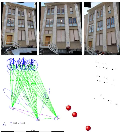
It is normal to compare image measurements with a corresponding (accurate) dataset to try out the accuracy of the reconstruction (Fig. 6). If the goal is the analysis of bundle adjustment accuracy, a possible solution is the use of independent check points. Obviously, in this case we are interested not only in an accuracy evaluation, but also in bundle statistics (sigma-naught and covariance matrices) to check the correctness of all algorithms implemented. The reference dataset consists in 28 photogrammetric targets (white dot and black background with a cross in the middle) placed on a building façade (9×12 m). The 3D coordinates were initially measured with a theodolite Leica TS30 and a geodetic network based on three stations (multiple intersection). The adjustment provided points with precision of about X = Z = ±0.3 mm (façade plane) and Y = ±0.5 mm (depth).
A total number of 3 convergent projections was then created with a Nikon D700 equipped with a 50 mm lens and image coordinates were measured manually (we assumed a precision of these points of ±1 pix). Bundle adjustment was carried out by including also all projection centres (measured with the theodolite after placing a 360° prism on top of the head), and 8 control points (a priori sigma naught of ±1 pix). This allows the registration of both projects in the same reference system and makes possible to analyse accuracy using the remaining check points. Obviously, as the head was calibrated using an optical alignment to obtain a precision of
a few millimetres, perspective centres were weighted using a precision X0= Y0= Z0=± 1 cm, whereas for 3D coordinates the precision given by geodetic network adjustment (always less than 1 mm) has been utilised.
The difference between the perspective centre coordinates measured with the theodolite (360° prism on top of the head and Z coordinates corrected using a known vertical shift) and the adjusted coordinates is also interesting (less than 1 cm, confirming the correct calibration of the head), as shown in Table 2.
Fig. 6. Projections, geodetic network with error ellipses (targets, image locations and stations), and 3D view of projection poses.
X Y Z
Mean (mm) -1.4 1.3 0.1
St.dev (mm) 1.0 1.2 1
Max (mm) 0.3 3.3 1.5
Min (mm) -3.0 -0.8 -1.75
Table 1. Difference statistics on a set of 20 check points.
X0 (mm) Y0 (mm) Z0 (mm)
Projection 1 -7.1 2.9 1.8
Projection 1 -7.9 -0.6 -3.5
Projection 3 2.4 -6.7 -7.7
Table 2. Differences between theodolite and image-based exterior orientation parameters.
3.2 Surface measurement
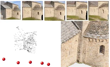
Fig. 7. Original images, orientation results and 3D point cloud from dense matching (ca 4 million points).
This approach is needed in order to preserve all the information contained in the gnomonic projections and process the images at the finest level (their original size). Indeed, an image matching approach based on subsampled images without a coarse-to-fine strategy contradicts the gnomonic projection concept. MGCM+ is a dense image matching algorithm developed to deal with high resolution images. The final model is obtained by processing the images at their full size so that high quality of the final result can be maintained. At the coarser level the tie points extracted in the orientation phase are meshed in order to obtain an approximate model of the surface. This initial model is then refined with MGCM+. In the next step the quasi-dense point cloud obtained is meshed again and the obtained surface is used as an initial model for the following iteration. Operatively, three iterations were used in the reported experiments.
The matching algorithm used here is based on the Multi-Photo Geometrically Constrained Matching – MGCM (Baltsavias, 1991) adapted to deal with dense reconstruction of 3D surfaces (not only 2.5D) for close-range applications. For this reason, it has been renamed MGCM+. Although the MGCM algorithm is more than twenty years old, probably it is still one of the most precise and reliable methods for image coordinate measurement. However, in order to improve its performances in the case of large and complex 3D objects, some improvements were needed: a proper selection method for the ‘master image’, the choice of the images to be matched together, the definition of reasonable approximate parameters in the linearized least squares problem, etc. Using the previously defined coarse-to-fine approach with an approximate model, some of the previously mentioned problems can be solved as described in Previtali et al. (2011). In fact, starting from a coarse model of the surface the ‘master image’ can be selected considering the image scale and the convergence angle. In a similar way the images to be matched together can be chosen using some visibility considerations preventing blunders due to the use of occluded parts. The problem of approximate parameters can be partially overcome using OE parameters and refined approximate models in different iterations.
The point cloud of the considered basilica was compared with a laser scanning dataset acquired by a Riegl LMS-Z420i (www.riegl.com), obtaining a discrepancy of about ±7 mm after the alignment with the ICP algorithm (Besl and McKay, 1992 - Fig. 8). This value is quite similar to the nominal precision of the laser scanner employed.
Fig. 8. Comparison between the point cloud extracted from the projections and laser scanner data: the discrepancy is 7 mm. The colour bar ranges from -0.03 to 0.03 m.
4. CONSIDERATIONS AND CONCLUSIONS
The use of gnomonic projections seems a promising field of research and does not modify significantly the traditional processing methods based on pinhole images.
The needed hardware is surely more cumbersome, as a tripod and a rotating head are mandatory to obtain precise results and remove parallax errors. The direct use of a hand-held digital camera is not here considered, although this case would deserve to be investigated in the future.
At the current development stage, gnomonic projections are created with image matching techniques. This requires an overlap between consecutive images and well-textured objects. This limitation can be overcome with motorized heads able to provide the rotation matrices of all single pinhole images. In this case it is possible to obtain projections with the same set of calibration parameters (even the sensor size) since a constant acquisition procedure can be replicated for all poses. Moreover, this kind of head is already available on the market and can be purchased for less than 1000 €. An alternative solution could be a robotic theodolite coupled with a camera. In this case, the theodolite could be directly used for image registration into a geodetic reference system.
It is important to underline that all calibration parameters of each single projection are known. The focal length f and the pixel size p are constant whereas the sensor size is increased depending on the rotation during image acquisition. If we consider a full frame sensor (e.g. Nikon D700 with a pixel size of 8.4 m) and a 35 mm lens, which is a quite standard configuration for real projects, we can assume that the gnomonic projection created with 200 mm lens gives a new image (using a similar field of view) of about 23800×23800 pix. This simple consideration stresses the potential of the method and makes easier to understand that the use of very long focal lenses (e.g. 600 mm – ca 71400×71400 pix) can produce images that cannot be easily processed with standard PCs (for this reason no longer focal length than 90 mm lens has been in the reported experiments).
(camera, GNSS, theodolite, terrestrial laser scanner), like during a standard survey. The adjustment is not here intended as an absolute orientation with a similarity transformation, but pseudo-observations are used to (i) remove the rank deficiency and (ii) to control block deformations, as shown in the example with theodolite data (Subsect. 31.).
The pipeline for 3D processing follows a coarse-to-fine approach to exploit the full potential of these images. Our solution uses the LSM algorithm during the orientation and surface reconstruction phases. Initial matches extracted from low resolution images with the SURF operator are considered as approximate locations and are then refined. The sub-pixel precision after bundle adjustment confirmed the validity of processing algorithms and the correctness of the mathematic models.
Obviously, the method is very attractive not only for 3D modelling, but also for metric rectification and especially for building facades. Many shots can be reduced to few (even just one) projections that can be processed quickly. Other similar interesting applications are the analysis of flat-like objects (e.g. paintings) where high resolution orthophotos can be produced.
To conclude, the direct use of this technique could overcome many limitations of traditional pinhole images. It is also noteworthy how a combined bundle adjustment (pinhole and gnomonic) is feasible as the general formulation does not change significantly. This means that gnomonic projections could be employed to reconstruct fine details whereas pinhole shots could provide a general network around the object. Further experiments will be carried out to try out the feasibility of this combined adjustment.
Acknowledgements
This project has been partially funded under the grant FIRB 2010. Acknowledgements go Kwang Hua Foundation, Tongji University (Shanghai, P.R. China).
REFERENCES
Baltsavias, E.P., 1991. Multiphoto Geometrically Constrained Matching. Ph. D. thesis, Inst. of Geodesy and Photogrammetry, ETH Zurich, Switzerland, Mitteilungen No. 49, 221 pp.
Barazzetti, L., Forlani, G., Remondino, F., Roncella, R. and Scaioni, M., 2011. Experiences and achievements in automated image sequence orientation for close-range photogrammetric projects. Proc. of SPIE Optics+Photonics, Vol. 8085, 23-26 May, Munich, Germany.
Uyttendaele, M., Eden, A. and R. Szeliski, 2001. Eliminating ghosting and exposure artifacts in image mosaics. Proc. CVPR’01, Vol. 2, pp 509-516
Bascle, B., Blake, A. and Zisserman, A., 1996. Motion deblurring and super-resolution from an image sequence. In Proc. of the Fourth European Conference on Computer Vision, Cambridge, England, 573–581
Berthod, M., Shekarforoush, H., Werman, M. and Zerubia, J., 1994. Reconstruction of high resolution 3D visual information. Proc. of the Conference on Computer Vision and Pattern Recognition, Seattle, WA, 654–657
Brown, M. and Lowe, D.G., 2007. Automatic panoramic image stitching using invariant features. International Journal of Computer Vision, 74(1): 59-73.
Burt, P. and Adelson, E., 1983. A multi-resolution spline with application to image mosaics. ACM Transactions on Graphics, 2(4): 217-236.
Dellaert, F., Thrun, S., and Thorpe, C., 1998. Jacobian images of super-resolved texture maps for model-based motion estimation and tracking. Proce. of the Fourth Workshop on Applications of Computer Vision, Princeton, NJ, 2–7
Elad, M. and Feuer, A., 1997. Restoration of single super-resolution image from several blurred, noisy and down-sampled measured images. IEEE Transactions on Image Processing, 6(12): 1646–58
Elad, M. and Feuer, A., 1999. Super-resolution restoration of an image sequence - adaptive filtering approach. IEEE Transactions on Image Processing, 8(3): 387–395
Granshaw, S.I., 1980. Bundle adjustment methods in engineering photogrammetry. Photogrammetric Record, 10(56): 181-207.
Hartley, R.I. and Zisserman A., 2004. Multiple View Geometry in Computer Vision. Second edition. Cambridge University Press, Cambridge, 672 pages.
Kauhanen, H., Heiska, N. and Kurkela, M., 2009. Long focal length panoramic imaging for photogrammetric reconstruction. Proc. of the 3D ARCH Conference, Trento, Italy, 5 pages, on CD-ROM
Irani, M, Rousso, B. and Peleg, S. Image sequence enhancement using multiple motions analysis, 1992. Proc. of the Conference on Computer Vision and Pattern Recognition, Urbana-Champaign, Illinois 216–221
Lowe, D.G., 2004. Distinctive image features from scale-invariant keypoints. International Journal of Computer Vision, 60(2): 91-110.
Milanfar, P., 2010. Super-Resolution Imaging. CRC Press, 490 pages
Numnonda, T., Andrews, M. and Kakarala, R., 1993. High resolution image reconstruction by simulated annealing. Image and Vision Computing, 11(4): 213–220
Previtali, M., Barazzetti, L., Scaioni, M., Yixiang, T. (2011). An automatic multi-image procedure for accurate 3D object reconstruction. 4th International Congress on Image and Signal Processing - IEEE Conference Record Number 18205, Shanghai, 15-17 October, 5 pages
Remondino, F. and Fraser, C., 2006. Digital camera calibration methods: considerations and comparisons. International Archives of Photogrammetry, Remote Sensing and Spatial Information Sciences, vol. XXXVI, 5, 266-272
Shekarforoush, H., Berthod, M, Zerubia, J. and Werman, M., 1996. Sub-pixel bayesian estimation of albedo and height. International Journal of Computer Vision, 19(3): 289–300