LAMPIRAN A : DATA SIMULASI
A.1 Iterasi Rancangan Antena Mikrostrip Patch Segiempat Konvensional
Gambar A.1.1 Iterasi Ukuran Patch
Gambar A.1.3 Iterasi Perubahan Posisi Pencatuan
(a) Tampilan 2 Dimensi
(b) Tampilan 3 Dimensi
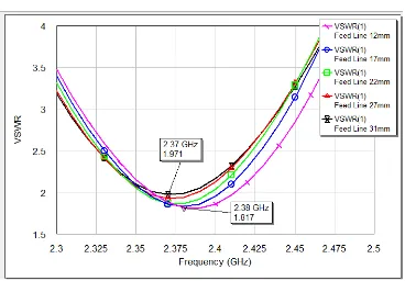
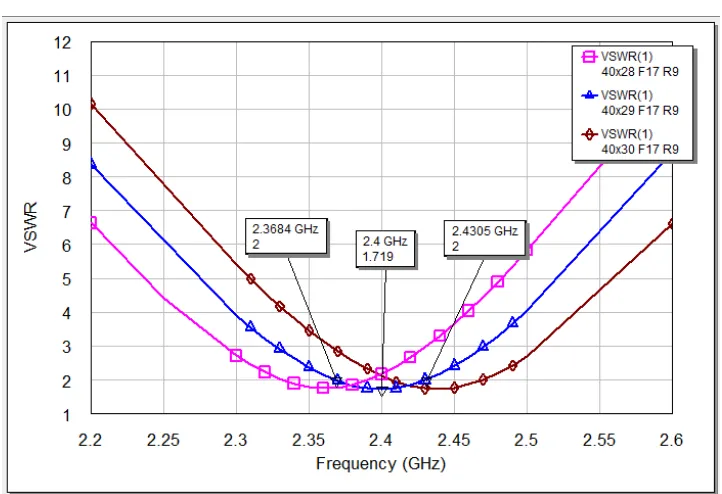
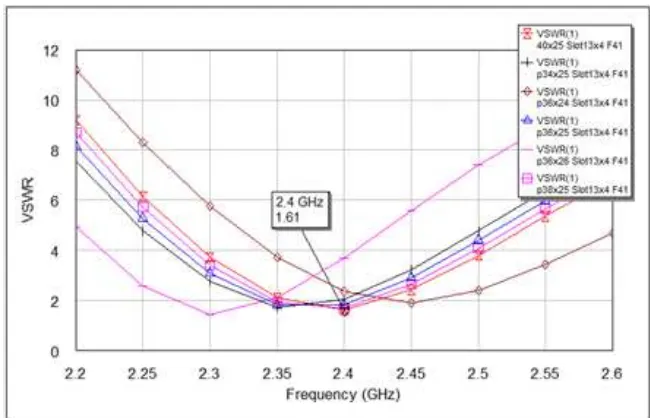
A.2 Iterasi Rancangan Antena Mikrostrip Patch Segiempat dengan Single Stub
A.3 Iterasi Rancangan Antena Mikrostrip Patch Segiempat dengan Pencatuan Aperture Coupled
Gambar A.3.1 Iterasi Ukuran Patch
Gambar A.3.3 Iterasi Panjang Saluran Pencatu
(a) Tampilan 2 Dimensi
(b) Tampilan 3 Dimensi
Gambar A.3.5 Rancangan Antena Mikrostrip Patch Segiempat Aperture Coupled
A.4 Iterasi Rancangan Antena Mikrostrip Patch Segiempat dengan Pencatuan Aperture Coupled dengan Gap Udara
Gambar A.4.1 Iterasi Ukuran Patch
Gambar A.4.3 Iterasi Panjang Saluran Pencatu
Gambar A.4.4 Iterasi Hasil Optimum
(b) Tampilan 3 Dimensi
Gambar A.4.5 Rancangan Antena Mikrostrip Patch Segiempat Aperture Coupled
LAMPIRAN B : DATA PENGUKURAN
B.1 Hasil Pengukuran Pola Radiasi Antena Mikrostrip Patch Segiempat dengan
B.2 Hasil Pengukuran Pola Radiasi Antena Mikrostrip Patch Segiempat Pencatuan Aperture Coupled
B.3 Hasil Pengukuran Pola Radiasi Antena Mikrostrip Patch Segiempat Pencatuan Aperture Coupled dengan Gap Udara
B.4 Hasil Fabrikasi Antena Mikrostrip Patch Segiempat dengan Single Stub
LAMPIRAN C : AWR DESIGN ENVIRONMENT
C.1 Introduction
The AWR Design Environment comprises two powerful tools that can be used together to create an integrated system and RF design environment: Visual System Simulator™ (VSS) and Microwave Office (MWO). These powerful tools are fully integrated in the AWR Design Environment and allow you to incorporate circuit designs into system designs without leaving the AWR Design Environment.
Microwave Office enables you to design circuits composed of schematics and electromagnetic (EM) structures from an extensive electrical model database, and then generate layout representations of these designs. You can perform simulations using one of Microwave Office’s simulation engines -- a linear simulator, an advanced harmonic balance simulator, a 3D-planar EM simulator (EMSight), or an optional HSPICE simulator -- and display the output in a wide variety of graphical forms based on your analysis needs. You can then tune or optimize the designs and your changes are automatically and immediately reflected in the layout.
VSS enables you to design and analyze end-to-end communication systems. You can design systems composed of modulated signals, encoding schemes, channel blocks and system level performance measurements. You can perform simulations using VSS’s predefined transmitters and receivers, or you can build customized transmitters and receivers from basic blocks. Based on your analysis needs, you can display BER curves, ACPR measurements, constellations, and power spectrums, to name a few. VSS provides a real-time tuner that allows you to tune the designs and then see your changes immediately in the data display.
At the core of MWO and VSS capability is advanced object-oriented technology. This technology results in software that is compact, fast, reliable, and easily enhanced with new technology as it becomes available.
Support is also available from the Applied Wave Research website at
Environment Help menu. The Support page provides links to the following:
• the current software version
• the KnowledgeBase, which contains Frequently Asked Questions (FAQs) from MWO and VSS users, Application Notes, Tutorials, and project examples
C.2 Design Flow
The basic design flow in the AWR Design Environment is shown in the following flow chart.
C.3 Starting Awr Programs
To start the AWR Design Environment: 1. Click Start on your desktop.
2. Choose Programs > AWR Suite 2004 > AWR Design Environment. The following AWR Design Suite main window displays.
C.4 AWR Design Environment Components
The AWR Design Environment contains the windows, components, menu selections and tools you need to create linear and nonlinear schematics, set up EM structures, generate circuit layouts, create system diagrams, perform simulations, and display graphs. Most of the basic procedures apply to both Microwave Office (MWO) and Visual System Simulator (VSS).
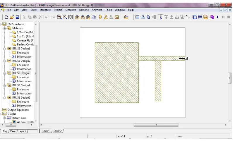
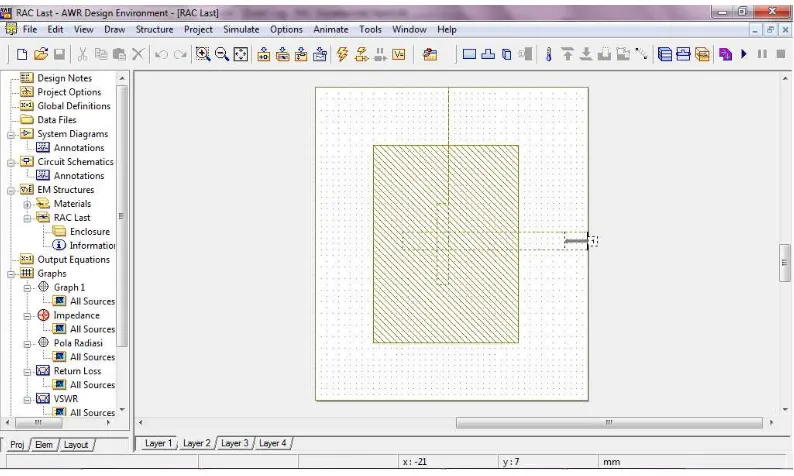
C.5 Creating EM Structures
C.6 Adding EM Structure Drawings
Before you draw an EM structure, you must define an enclosure. The enclosure specifies things such as boundary conditions and dielectric materials for each layer of the structure. To define an enclosure, double-click Enclosure under your new EM structure in the Project Browser to display a dialog box in which you can specify the required information.
After you define the enclosure, you can create drawings by accessing options from the Draw menu to draw components such as rectangular conductors, vias, and edge ports. You can view EM structures in 2D (structure) and 3D by using the View menu, and you can view currents and electrical fields using the Animate menu.
C.7 Creating Output Graphs and Measurements