Hybrid Mesh Ad-hoc On-demand Distance Vector
Routing Protocol
Asad Amir Pirzada, Marius Portmann
∗and Jadwiga Indulska
∗Queensland Research Laboratory, National ICT Australia Limited,
Brisbane, QLD 4000, Australia.
{asad.pirzada,marius.portmann,jadwiga.indulska}@nicta.com.au
Abstract
Wireless Mesh Networks (WMNs) have recently gained increasing attention and have emerged as a technology with great potential for a wide range of applications. WMNs can be considered as a super-set of traditional mobile ad-hoc networks (MANETs), where the network is comprised of mobile client de-vices (MESH CLIENTs). In addition toMESH CLIENTs, a WMN can also contain relatively static devices called
mesh routers (MESH ROUTERs). Such hybrid WMNs
are characterized by a high level of heterogeneity, since staticMESH ROUTERs are typically much less
re-source constrained than mobile MESH CLIENTs, and
are also often equipped with multiple radio inter-faces. Traditional ad-hoc routing protocols do not differentiate between these types of nodes and there-fore cannot achieve optimal performance in hybrid WMNs. In this paper, we propose simple extensions to the Ad-hoc On-demand Distance Vector (AODV) routing protocol, which aim to take advantage of the heterogeneity in hybrid WMNs by preferentially routing packets via paths consisting of high
capac-ity MESH ROUTERs. In addition, we implement a
sim-ple channel selection scheme that reduces interfer-ence and maximizes channel diversity in multi-radio WMNs. Our simulation results show that in hybrid WMNs, our extensions result in significant perfor-mance gains over the standard AODV protocol.
Keywords: Wireless Mesh Networks, Routing, Hybrid
Mesh Networks, Channel Diversity
1 Introduction
Wireless Mesh Networks (WMNs) are self-organizing and self-configuring wireless networks, typically im-plemented with IEEE 802.11 hardware. In conven-tional wireless LANs, clients communicate with ac-cess points via a single-hop wireless link and acac-cess points are interconnected via a wired backbone in-frastructure. WMNs do not rely on such a wired backhaul and implement connectivity via a wireless multi-hop network. Their robustness, self-organizing and self-configuring nature, and the low cost of wide area deployment make WMNs an attractive platform for a wide range of applications, such as public safety and emergency response communications, intelligent transportation systems, or community networks.
*The authors are also affiliated with the School of Informa-tion Technology and Electrical Engineering, The University of Queensland, Brisbane, QLD 4072, Australia.
Copyright c°2007, Australian Computer Society, Inc. This pa-per appeared at the Thirtieth Australasian Computer Science Conference (ACSC2007), Ballarat, Australia. Conferences in Research and Practice in Information Technology (CRPIT), Vol. 62. Gillian Dobbie, Ed. Reproduction for academic, not-for profit purposes permitted provided this text is included.
We can differentiate between two types of
nodes in a WMN: MESH ROUTERs and MESH CLIENTs.
MESH ROUTERs are relatively powerful and static
nodes, which have either access to mains power or are equipped with high capacity batteries. In addition,
MESH ROUTERs typically have multiple radio interfaces,
which significantly increases the transmission capac-ity if the radios are operated on orthogonal channels. In contrast toMESH ROUTERs,MESH CLIENTs are rela-tively resource constrained mobile client devices, such as WiFi-enabled PDAs. These devices usually have only a single radio interface and their key constraint is limited battery power.
A WMN that is entirely comprised of
MESH ROUTERs is referred to as an infrastructure
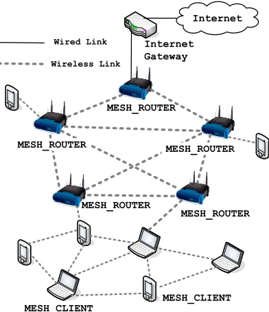
WMN, whereas a client WMN is a network made up of client devices only (Akyildiz & Wang 2005). A client WMN is essentially identical to a pure mobile ad-hoc network (MANET) (Pirzada, McDonald & Datta 2006), and we can therefore consider WMNs a superset of MANETs. A hybrid WMN, such as illustrated in Fig. 1, consists of both MESH ROUTERs
and MESH CLIENTs, with both types of nodes
per-forming routing and forwarding functionality. In this case, MESH ROUTERs form the (wireless) backbone of
a hybrid WMN, whereas MESH CLIENTs can be seen
as a dynamic extension.
Current routing protocols for WMNs can be roughly grouped into two categories. The first cat-egory consists of protocols that are based on tradi-tional routing protocols for wired networks such as RIP (Routing Information Protocol) or OSPF (Open Shortest Path First). Since these protocols are not able to handle node mobility or highly dynamic net-works in general, their application is restricted to
atively static infrastructure WMNs.
The second category consists of protocols that are based on MANET routing protocols. Tremendous re-search efforts have been made in this area over the last few years and an impressive number of mobile ad-hoc routing protocols has been proposed (Royer & Toh 1999). These protocols were designed for net-works with highly mobile and typically power con-strained devices. As a consequence, they are able to handle node mobility and the generally dynamic na-ture of client WMNs and hybrid WMNs, which is why they form the basis of most current WMN routing protocols.
However, since these routing protocols have been designed for relatively homogeneous MANETs, con-sisting entirely of resource constrained mobile devices, they do not perform optimally in highly heteroge-neous hybrid WMNs. Current WMN routing pro-tocols do not differentiate between different types of nodes (MESH CLIENTs andMESH ROUTERs) in the net-work and are therefore unable to take full advantage
of high capacity MESH ROUTERs in hybrid WMNs.
A fundamental problem of multi-hop wireless net-works in general and WMNs in particular is the lim-ited scalability and the degradation of performance with increasing path length. One approach to over-come this problem is to use multiple radio interfaces per node, operating on orthogonal channels. Multi-radio nodes have significantly increased capacity, due to reduced interference and the ability of full-duplex communication, which is not supported by single ra-dio nodes. In order to achieve optimal performance in a multi-radio WMN, an efficient channel allocation and selection scheme is required. Even with complete knowledge of the network topology, optimal channel assignment is very difficult to achieve and is consid-ered an NP-hard problem (Raniwala & Chiueh 2005). The routing protocol presented in this paper aims to achieve two goals. First, it tries to make
opti-mal use of high capacity MESH ROUTERs in a hybrid
WMN by routing packets along paths consisting of
MESH ROUTERs whenever possible. This not only
in-creases the overall throughput and reduces latency, it also helps to conserve the battery power of client devices. Secondly, we present a very simple yet effec-tive scheme that tries to maximize per-path channel diversity. For example, the scheme aims to prevent the use of the same channel on neighbouring links of an end-to-end path, which would lead to significant interference and performance degradation.
The Ad-hoc On-demand Distance Vector (AODV) routing protocol (Perkins, Royer & Das 2003) forms the basis of our work. AODV is a popular reactive MANET routing protocol with excellent scalability properties. Even though AODV has inherent sup-port for multi-radio nodes, it lacks built-in supsup-port for optimal channel or interface selection and is there-fore unable to maximize channel diversity. AODV has been designed for homogeneous MANETs where nodes have similar computational communication re-sources and are also similar in terms of their level and pattern of mobility. Thus, AODV will not be able to perform optimally if deployed on a hybrid WMN with high capacity MESH ROUTERs that are static and are equipped with multiple radios.
In this paper, we present an extended version of AODV, called AODV-HM (AODV-Hybrid Mesh). The key contributions of our work are:
• We propose a simple modification of AODV’s
route discovery mechanism to allow selection of
paths which maximize the use of MESH ROUTERs
and minimize the involvement of MESH CLIENTs.
These routes are more stable due to the lower mobility of MESH ROUTERs and provide lower
la-tency, improved packet delivery rates and a lower control packet overhead.
• We integrate a channel selection scheme into
AODV’s route discovery mechanism which in-creases channel diversity of end-to-end paths. This reduces interference and contention and fur-ther increases the packet delivery rate and re-duces latency.
The remainder of the paper is organized as fol-lows: Section 2 discusses relevant related work. The AODV-HM protocol is explained in Section 3. In Sec-tion 4 we provide details of our simulaSec-tion environ-ment. Simulation results and their analysis are pre-sented in Section 5 with concluding remarks in Sec-tion 6.
2 Related Work
2.1 Hyacinth
Hyacinth (Raniwala & Chiueh 2005) is a multi-channel static wireless mesh network protocol that uses multiple radios and channels to improve the net-work performance. It supports a fully distributed channel assignment algorithm, which can dynamically adapt to varying traffic loads. It uses a spanning-tree based routing algorithm to load balance the network as well as to rectify route failures. TheMESH ROUTERs having access to the wired network are considered as the root nodes of the spanning tree. Hyacinth’s chan-nel assignment algorithm breaks a single-chanchan-nel col-lision domain into multiple colcol-lision domains, each op-erating on a different frequency. The channel assign-ment algorithm operates in two phases: Neighbour-Interface Binding and Neighbour-Interface-Channel Assignment. In the first phase each node separates its interfaces into UP-NICs and DOWN-NICs. Each node has con-trol to change the channel on its DOWN-NICs only. During the second phase each node exchanges a peri-odic message, which contains the channel usage sta-tus, with its neighbours in the interference range. Us-ing the per-channel total load information a node can issue a change channel message to its neighbour in order to switch to a least used channel. The advan-tage of this channel assignment scheme is that a fat-tree architecture is obtained in which links close to the root of the spanning tree are given higher band-width. The channel assignment is further integrated with the routing process. Each node having routing information to the root advertises this information to one-hop neighbours. This advertisement also contains the cost metric, which comprises of the hop-count and the residual uplink capacity. Each node receiving this advertisement makes a decision, based upon the cost, as regards to joining the advertising node. If the node decides to join, it sends an acceptance message to the advertising node and a departing message to the par-ent node with which it was previously attached. New
nodes joining the network broadcastHELLO packets,
such as to initiate the joining process by the neigh-bouring nodes.
2.2 Single-Radio Multi-Channel Routing
Protocol
that once the route is established, nodes are not re-quired to switch channels for the duration of the flow. The protocol considers all nodes in the network to be in essentially one of four states: free, locked, switch-ing or hard-locked. The free nodes are nodes that are not supporting any flow at the moment. Locked nodes are those that are currently supporting one flow. A switching node is one that is supporting two or more flows on different channels. A hard-locked node is one, which due to certain constraints, cannot become a switching node. MCRP benefits from mul-tiple channels without modifying the MAC protocol. The routing scheme is similar to that of AODV. How-ever, each Route Request packet (RREQ) is broadcast on each channel in a round robin manner and each receiving node also rebroadcasts theRREQ. Intermedi-ate nodes also creIntermedi-ate a Reverse Route to the source and maintain a channel number for the next hop with each Reverse Route table entry. To convey the chan-nel information of the next hop, each RREQ contains the operating channel1number of the hop sending the RREQ. The RREQ also contains the channel table and flow table to be propagated along with eachRREQ. The channel table contains the count of similar channels being consecutively used on a single flow path. The flow tables maintain a count of simultaneous flows being carried out on a single channel. These tables are used by the destination node to make a decision regarding the selection of the optimal route from mul-tiple receivedRREQs. The Route Reply packet (RREP) is unicast from the destination to the source on the
optimal path. All nodes forwarding the RREQchange
their operating channels to the channel selected by the destination.
2.3 Multi-Radio Link Quality Source
Rout-ing
The Multi-Radio Link Quality Source Routing (MR-LQSR) (Draves, Padhye & Zill 2004) protocol has been developed by Microsoft for static community wireless networks. The protocol works in conjunc-tion with the Mesh Connectivity Layer (MCL). The MCL permits higher layer applications to connect to the wireless mesh network using Wi-Fi or WiMAX. The MCL implements an interposition layer between the link and network layers. It essentially consists of a loadable driver, which acts as a virtual network adapter with the ability to multiplex several physical adapters. Routing of packets is carried out by MR-LQSR, which is an optimized version of the Dynamic Source Routing (DSR) protocol. The MR-LQSR pro-tocol assumes that the number of wireless interfaces is equal to the number of channels being used in the network. The protocol identifies all nodes in the wire-less mesh network and assigns weights to all possible links. To do so, the link information including chan-nel assignment, bandwidth and loss rates are prop-agated to all nodes in the network. This propaga-tion is combined with the delivery of DSR control packets. The Expected Transmission Time (ETT) on each link is computed using the Expected Transmis-sion Count (ETX), bandwidth and packet loss. The ETT metric is further used to compute the Weighted Cumulative Expected Transmission Time (WCETT), which defines the path metric designed for multi-radio WMNs. The WCETT is then applied to the Link Cache scheme of the DSR protocol. In native DSR, the default cost of links is set to one. Hence, when the Dijkstra algorithm is executed over the link cache by a source node, the shortest path in terms of num-ber of hops is always returned. However, when the
1
The operating channel of a node is the default channel on which it is generally listening on.
WCETT is used as the link cost, the protocol aims to return the path in terms of link bandwidth, loss rate and channel diversity.
2.4 Multi-Channel Routing Protocol
The Multi-Channel Routing (MCR) protocol
(Kyasanur & Vaidya 2006) has been developed for dynamic WMNs, where nodes have multiple wireless interfaces, each supporting multiple channels. The protocol makes use of an interface switching mech-anism to assign interfaces to channels. Two types of interfaces are assumed: fixed and switchable. In fixed interfaces, K number of interfaces out of a total M interfaces are assumed to be operating on K fixed channels. In the switchable interfaces, the remaining interfaces are dynamically assigned to any of the remaining channels. Switching is carried out depending upon the maximum number of data packets queued for a single channel. Multiple queues are maintained for all switchable interfaces. Each node maintains a neighbour table and a channel usage list. The neighbour table contains information regarding the fixed channels used by the node’s
neighbours. The channel usage list contains the
count of nodes that are using each channel as their fixed channel. Each node periodically transmits a
HELLO packet on all channels, containing the node’s
fixed channel number. Each node receiving theHELLO packet updates its neighbour table and channel usage
list. The information from the table and list is
used to control the channel and interface
switch-ing mechanism. The switching mechanism assists
the MCR protocol in finding routes over multiple channels. MCR uses a new routing metric, which is computed as a function of channel diversity, interface switching cost and hop-counts. The diversity cost is assigned according to the least number of channels used in a route. Thus, a route with a larger number of distinct channels in a route is considered to be having a lower diversity cost. The switching cost is used to minimize the frequent switching of wireless interfaces. The route discovery mechanism of MCR
is similar to that of DSR. In addition, each RREQ
also contains the channel number and switching
cost. When the destination receives the RREQ, it
computes the diversity cost (number of channels in
the RREQ) and the switching cost (sum of all link
switching costs). These costs help the destination in determining and selecting the optimal path available between the source and the destination.
Table 1 presents a comparison of the discussed pro-tocols. All protocols assume homogeneous node con-figurations i.e. equal number of interfaces and do not differentiate between different node types. Hyacinth and MR-LQSR have been specifically designed for in-frastructure WMNs and have no support for client
mobility. Hyacinth, MR-LQSR and MCR use
Table 1: Comparison of Recent WMN Protocols
Protocols Research Group
Year Type Mobility Derivative Routing Met-ric
Remarks
Hyacinth Stony Brook University
2005 Multi-Radio
No Spanning Tree
Hop Count, link/path loads
Independent channel switch-ing protocol required.
MCRP University of Illinois, Urbana-Champaign
2004 Single-Radio
Yes AODV Hop Count High speed interface switch-ing required.
Complex to handle multiple flows.
MR-LQSR Microsoft Research
2004 Multi-Radio
No DSR WCETT Proprietary Mesh Connectiv-ity Layer.
Bandwidth computed using packet probes.
Requires propagation of in-termediary node ETT’s to source node.
MCR University of Illinois, Urbana-Champaign
2006 Multi-Radio
Yes DSR Channel di-versity and switching cost
Hybrid of fixed and switch-able channels.
Periodic distribution of chan-nel usage lists.
3 Mesh-Aware AODV Protocol
3.1 Standard AODV
The AODV is inherently a distance vector routing protocol that has been optimised for ad-hoc wireless networks. It is an on demand or reactive protocol, as it finds the routes only when required. AODV borrows basic route establishment and maintenance mechanisms from the DSR protocol, and hop-to-hop routing vectors from the Destination-Sequenced Distance-Vector (DSDV) routing protocol. To avoid the problem of routing loops, AODV makes extensive use of sequence numbers in control packets. When a source node intends to communicate with a desti-nation node whose route is not known, it broadcasts a Route Request packet (RREQ). Each RREQ contains an ID, source and destination node IP addresses, and sequence numbers together with a hop count and con-trol flags. The ID field uniquely identifies the RREQ; the sequence numbers indicate the freshness of control packets and the hop-count maintains the number of nodes between the source and the destination. Each
recipient of the RREQ that has not seen the source
IP and RREQ ID pair or does not have a fresher (with larger sequence number) route to the destina-tion rebroadcasts the same packet after incrementing the hop-count.
Intermediate nodes create and preserve a Reverse Route to the source node for a certain interval of time.
When the RREQ reaches the destination node or any
node that has a fresh route to the destination, a Route Reply packet (RREP) is generated and unicast back to the source of the RREQ. Each RREP contains the des-tination sequence number, the source and the desti-nation IP addresses, route lifetime, and a hop count and control flags.
Each intermediary node that receives theRREP in-crements the hop-count, establishes a Forward Route to the source of the packet, and transmits the packet via the Reverse Route. To preserve connectivity in-formation, each node executing AODV can use link-layer feedback or periodicHELLOpackets to detect link breakages to nodes that it considers as its immediate neighbours. In case a link break is detected for a next hop of an active route, a Route Error packet (RERR) is sent to its active neighbours that were using that particular route.
When using AODV in a network with multi-radio nodes, each RREQ is broadcast on all interfaces. In order to avoid broadcast storms, a random delay is added in the transmission of each RREQ.
Intermedi-ate nodes with one or more interfaces operating on a shared channel, receive theRREQ and create a Re-verse Route that points towards the source node. If
the RREQ is a duplicate, it is simply dropped. The
first receivedRREQreceived by the destination or any intermediary node is selected and all otherRREQs are discarded. TheRREP is generated in response to the selectedRREQ, and is sent back to the source node on the existing Reverse Route.
3.2 AODV-HM
We have made the following assumptions for the de-sign and evaluation of our AODV-HM protocol:
• AllMESH CLIENTs andMESH ROUTERs should have
at least one common operating channel.
• The transmission and reception ranges of the
wireless transceivers are comparable.
• The wireless antennas are omni-directional. The aim of AODV-HM is to maximize the in-volvement of MESH ROUTERs into the routing process without significantly lengthening the paths. In addi-tion, we want to maximize channel diversity in the selected paths. To implement these features we make
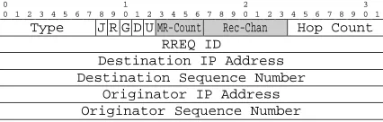
two changes to the RREQ header. First, we add a
4-bit counter (MR-Count) indicating the number of
MESH ROUTERs encountered on the path taken by the
RREQ. We further add a 7-bit field (Rec-Chan), which advertises the optimal channel to be used for the Re-verse Route. We have used the existing 11 reserved bits in theRREQ header. The first four bits represent the MR-Count while the remaining seven represent the Rec-Chan as shown in Fig. 2.
0 1 2 3 0 1 2 3 4 5 6 7 8 9 0 1 2 3 4 5 6 7 8 9 0 1 2 3 4 5 6 7 8 9 0 1
Type J R G D U MR-Count Rec-Chan Hop Count RREQ ID
Destination IP Address Destination Sequence Number
Originator IP Address Originator Sequence Number
Figure 2: AODV-HM Route Request Packet Header
3.2.1 Discovery of MESH ROUTERs
Whenever a MESH CLIENT intends to communicate
Receive RREQ
Select Min (Hop-Count–MR-Count) RREQ
Rec-Chan= Vacant Channel MR-Count ++
Create Reverse Route on Rec-Chan
Figure 3: RREQProcessing in AODV-HM
its routing table, it broadcasts a RREQ on all of its interfaces. Prior to the broadcast, it also sets the
MR-Count in the RREQ to zero. Each MESH ROUTER
forwarding the RREQ increments the MR-Count field
by one. When the RREQ is received by the
destina-tion or any intermediary node that can respond, the process shown in Fig. 3 is initiated.
If the RREQ has not been received earlier2, a RREQ-Timer is started and a RREQ-Counter is ini-tialized. The RREQ-Timer determines the amount of time a node should wait after receipt of the first
RREQ and before forwarding the optimal RREQ. The
RREQ-Timer helps to evaluate alternate copies of the
same RREQ arriving via different paths. The
RREQ-Counter maintains a count of these copies. All copies of theRREQare then buffered until the time when ei-ther the RREQ-Timer expires or the RREQ-Counter reaches a certain threshold.
The optimal values for the RREQ-Timer and Counter are primarily dependent upon the average node density. In case the density is high, the RREQ-Counter will reach its threshold value well within the RREQ-Timer. However, in case of a sparse network, the RREQ-Counter may never reach its threshold value before the RREQ-Timer expires. In the stan-dard AODV protocol, the minimum Route Discovery Latency (RDL), i.e. time between transmission of the first RREQ and the receipt of its correspondingRREP, is
RDL = 2×np×NODE TRAVERSAL TIME
where np is the number of nodes on the path
(excluding the source node) taken by the RREP.
NODE TRAVERSAL TIME is the approximate time taken by a packet to pass through one node.
For lower RREQ-Counter values in high density networks, AODV-HM incurs a RDL similar to that
2
Determinable through the Source IP andRREQID mapping.
of the standard AODV. However, in sparse networks with large RREQ-Counter values, AODV-HM may incur a maximum RDL of:
RDL = np×NODE TRAVERSAL TIME +
np×RREQ-Timer
In order to minimize the RDL, a low value of the RREQ-Counter is maintained or the RREQ-Timer is kept as close to the NODE TRAVERSAL TIME as possible.
When the Timer expires or the RREQ-Counter threshold is reached, theRREQ, for which the routing metric (Hop-Count - MR-Count) is minimal, is selected. This selection is done from the set of n
RREQs, stored in the RREQ Buffer (RREQ-BUFF), as
indicated in Equation 1.
RREQs=RREQi| min
1≤i≤n(Hop-Counti−MR-Counti) (1)
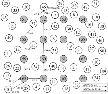
Let’s consider the scenario shown in Fig. 4, where
MESH CLIENT-5 (Source) wants to communicate with
MESH CLIENT-45 (Destination).
The darker nodes represent theMESH ROUTERs and
the remaining nodes are MESH CLIENTs. Standard
AODV does not distinguish between MESH ROUTERs
andMESH CLIENTs. Accordingly, when a route
discov-ery is initiated fromMESH CLIENT-5 forMESH CLIENT -45, the first arriving RREQ at MESH CLIENT-45 estab-lishes the route. The first route, between the source and destination, established using standard AODV is represented as follows:
RSD1= (5→63→59→55→37→45)
RouteRSD1has a hop-count of five and contains three
intermediary MESH ROUTERs and one MESH CLIENT.
However, there may be occasions where the firstRREQ arriving at the destination contains noMESH ROUTERs,
e.g. RSD = 5→22→14→35→37→45. If
MESH CLIENTs operate on a single channel, as is
typ-ically the case, the above scenario would lead to a significant performance degradation over a route con-sisting only of MESH CLIENTs (Li, Blake, Couto, Lee & Morris 2001).
In contrast, AODV-HM is able to create Reverse
Routes that traverse predominantly MESH ROUTERs
by delaying RREQs at intermediary nodes and
se-lectively forwarding the one consisting mostly of
MESH ROUTERs, instead of the first one to arrive.
For example, MESH ROUTER-60 is likely to receive
more than oneRREQs originating from MESH CLIENT -5. In case the firstRREQ reachesMESH ROUTER-60 via
32
MESH CLIENT-34 (with MR-Count=1), and theRREQ
reaches MESH ROUTER-60 via MESH ROUTER-64 (with
MR-Count=2), AODV-HM would select the latter which contains the smaller number of MESH CLIENTs.
In standard AODV, MESH ROUTER-60 would simply
forward the firstRREQreceived fromMESH CLIENT-34. Similarly, more than oneRREQs are received by the destination MESH CLIENT-45. Let’s assume fiveRREQs
from MESH CLIENT-5 have reached MESH CLIENT-45
and stored in the RREQ-BUFF. The paths taken by the five RREQs are as follows:
RSD1 = 5→63→34→35→37→45
RSD2 = 5→63→59→55→51→45
RSD3 = 5→63→59→55→51→20→45
RSD4 = 5→63→64→60→56→52→45
RSD5 = 5→63→64→40→6→7→45
Now using Eq. 1, we get the minimum difference be-tween the Hop-Count and MR-Count for the above routes as follows: RSD1: 5 - 1 = 4,RSD2: 5 - 4 = 1,
RSD3: 6 - 4 = 2,RSD4: 6 - 5 = 1 andRSD5: 6 - 2 = 4 respectively. The minimum cost is achieved using theRREQ that arrived via routesRSD2 andRSD4. In case two or moreRREQs have the same cost, the first of these to arrive is responded to and the corresponding route is established.
3.2.2 Channel Diversity
In a wireless network, as the physical medium is shared, nodes have to constantly contend with each other to gain access to the network. All nodes before making a transmission execute the Carrier Sense Mul-tiple Access with Collision Avoidance (CSMA/CA) protocol to avoid future collisions (IEEE 1997). The effectiveness of the CSMA/CA protocol is influenced by the density, mobility and traffic pattern of the net-work (Bianchi 2000). In order to minimize packet col-lisions and contention, the physical medium is gener-ally segregated using non-interfering channels. This in turn reduces the number of nodes contending per channel, which also lowers the number of packet col-lisions.
As mentioned earlier, the standard AODV pro-tocol typically adds some random delay prior to the transmission of RREQs over multiple interfaces. Thus, the Reverse and Forward Routes may or may
not have similar channel assignments3. For
ex-ample, in Fig. 4 the route between MESH CLIENT
-5 and MESH CLIENT-45 indicated with dashed
ar-rows includes three MESH ROUTERs: 55, 59 and 63.
Let’s assume that the MESH CLIENTs have one radio
each operating on Channel 1 (CH-1) and that the
MESH ROUTERs have three radios each, operating on
Channel 1 (CH-1), Channel 6 (CH-6) and Channel 11 (CH-11) respectively. During the route discov-ery process, MESH ROUTER-63 introduces a small
ran-dom delay before forwarding the RREQ on each of
its three channels. If we assume the smallest
de-lay is selected for CH-6,MESH ROUTER-59 receives the
first RREQ via this channel. In this case, the
Re-verse Route is created to MESH CLIENT-5 via CH-6.
When MESH ROUTER-59 retransmits theRREQ, it
em-ploys a similar mechanism. However, this time the firstRREQto reachMESH ROUTER-55 is via CH-1. Thus,
MESH ROUTER-55 creates the Reverse Route to the
source MESH CLIENT-5 via CH-1. Similarly, the
Re-verse Route from MESH CLIENT-37 is created via CH-1. This essentially introduces another collision
do-main between MESH ROUTER-59 and MESH CLIENT-37.
3
The firstRREQreceived on any interface determines the channel
used for the Reverse Route to the source node.
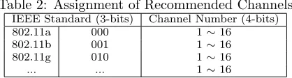
Table 2: Assignment of Recommended Channels
IEEE Standard (3-bits) Channel Number (4-bits)
802.11a 000 1∼16
802.11b 001 1∼16
802.11g 010 1∼16
... ... 1∼16
Packets sent from MESH ROUTER-59 to MESH ROUTER
-55, as well as packets sent from MESH ROUTER-55 to
MESH CLIENT-37 have to contend for the same medium
since they all share the same common channel (CH-1). Thus, the worst case channel selection strategy scenario for a route traversing through nodes with multiple radios may degrade to that of a path com-prised of single-radio nodes.
In AODV-HM, we use a simple mechanism to achieve effective channel assignment during route
dis-covery. Each node, before propagating a RREQ,
ap-pends the Recommended Channel (Rec-Chan) to the RREQ, as shown in Fig. 2 and Fig. 3. The Rec-Channel informs theRREQrecipient about the desired channel to be used for creating the Reverse Route. The Rec-Chan value is implemented as a 7 bit number, and its value is set according to Table 2. The first three bits define the IEEE physical layer standard the ra-dio is operating on. The following 4 bits indicate the specific channel number. For example, in the network shown in Fig. 4, allMESH CLIENTs are operating a sin-gle radio and are tuned to CH-1 of 802.11b. In this case, Rec-Chan will have a value of 17 (0010001). If a node operates only one radio, the Vacant Channel is the current operating channel. A node with multiple radios has the discretion to recommend any Vacant Channel. The Vacant Channel is selected based upon the following two criteria:
• The Rec-Chan is not interfering with the channel being used on the Reverse Route.
• The Rec-Chan is the least loaded channel. ARREQ can be received by a multi-radio node on one of its Receive Channels (Rx-Chan). However, de-pending upon the current assignment of channels to the interfaces, the Rx-Chan may or may not be equal to the Rec-Chan. For example, a node could have all of its radios tuned to channels other than the Rec-Chan, which would make it impossible create a Re-verse Route using the Rec-Chan. In case a node has an interface operating on Rec-Chan, it creates the Reverse Route to the previous hop using that inter-face, otherwise it creates the Reverse Route via the Rx-Chan.
Coming back to the example of Fig. 4, before ini-tiating the RREQ, MESH CLIENT-5 sets the Rec-Chan
to its current operating channel, i.e. CH-1. As
MESH CLIENT-5 is a single radio node, the RREQ is
received by MESH ROUTER-63 on CH-1 only. In this
case Rx-Chan is equal to Rec-Chan, soMESH ROUTER -63 creates the Reverse Route toMESH CLIENT-5 using
CH-1. MESH ROUTER-63 is operating on three
chan-nels, i.e. CH-1, CH-6 and CH-11. Using the criteria mentioned above, it now selects the Vacant Channel to be equal to CH-6. The Rec-Chan is then set to the
Vacant Channel and the RREQ is broadcast over all
three interfaces. MESH ROUTER-64, which is also op-erating the same three channels, now receives three
RREQs from MESH ROUTER-63. Since the Rec-Chan in
all threeRREQs is CH-6, MESH ROUTER-64 creates the
Reverse Route toMESH ROUTER-63 using CH-6.
In our example, MESH CLIENTs are operating on
0 5 10 15 20
Aggregate Goodput (bps)
0 5 10 15 20
Packet Delivery %age
0 5 10 15 20
Routing Packet Overhead
0 5 10 15 20
Average Latency (seconds)
0 5 10 15 20
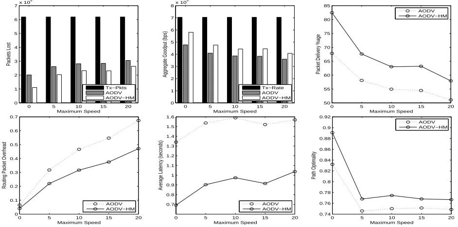
Figure 5: Results of Simulation 1
also does not interfere with the channel used on the Reverse Route. Similarly,MESH ROUTER-60 creates the Reverse Route via CH-11 and recommends the Vacant Channel CH-6. In this manner, AODV-HM creates
a route between MESH CLIENT-5 andMESH CLIENT-45
with less interference and contention compared to the route that is selected by standard AODV.
The routing metric used in AODV-HM aims to
minimize the number of MESH CLIENTs present in a
particular route. This may seem analogous to short-est path routing, but this is not the case, since the metric attempts to route traffic through the
MESH ROUTERs, which in turn maximize the stability
and channel diversity of the routes. A number of other routing metrics like ETX, ETT and WCETT
also exist. Of these metrics, only WCETT takes
advantage of the channel diversity, however, its di-rect application to AODV, which is a distance vec-tor routing protocol, requires extensive modifications to the protocol’s inherent working (Ramachandran, Buddhikot, Chandranmenon, Miller, Belding-Royer & Almeroth 2005).
4 Simulation Environment
We evaluated the efficiency of the AODV-HM proto-col through extensive simulations in NS-2 (NS 1989), using the Extended Network Simulator (ENS) exten-sions (Raman & Chebrolu 2005). A WMN covering an area of 1 square km is established using uniformly
distributed static MESH ROUTERs and randomly
dis-tributed mobileMESH CLIENTs. Concurrent UDP
con-nections are established between randomly selected source and destinationMESH CLIENTpairs. A total of four simulations were conducted to evaluate the per-formance of the AODV-HM protocol under varying mobility, traffic load and node configurations. The parameters common to all four simulations are listed in Table 3. The simulations provide the following per-formance metrics:
Packets Lost: The number of data packets that were lost due to unavailable or incorrect routes, MAC layer collisions or through the saturation of interface queues.
4
The values of these parameters are varied in Simulations 1, 2, 3 and 4 respectively.
Table 3: Simulation Parameters
Examined protocols AODV and AODV-HM
Simulation time 900 seconds Simulation area 1000 x 1000 m Propagation model Two-ray Ground
Re-flection
Mobility model forMESH CLIENTs Random waypoint Maximum speed ofMESH CLIENTs4 1 m/s
Transmission range 250 m Number of connections4 30
Traffic type CBR (UDP)
Packet size 128 bytes
Packet rate 25 pkts/sec Number ofMESH ROUTERs4 25
Number ofMESH ROUTERInterfaces4 3
Number ofMESH CLIENTs 50 Number ofMESH CLIENTInterfaces 1
MESH CLIENTRREQ-Counter 5 packets
MESH ROUTERRREQ-Counter 25 packets
MESH CLIENTRREQ-Timer 50 ms
MESH ROUTERRREQ-Timer 250 ms
Aggregate Goodput: The number of data bits suc-cessfully transmitted in the network per second.
Packet Delivery Percentage: The ratio between the number of data packets successfully received by destination nodes and the total number of data pack-ets sent by source nodes.
Routing Overhead: The ratio of the total number of control packets generated to the total number of received data packets.
Average Latency:The mean time in seconds taken by data packets to reach their respective destinations.
Path Optimality: The ratio between the length (number of hops) of the shortest possible path and the actual path taken by data packets.
5 Results and Analysis
5.1 Simulation 1 : Varying the MESH CLIENT
Speeds
In Simulation 1, we have varied the maximum speed
of theMESH CLIENTs from 0 m/s to 20m/s, with
10 20 30 40 50
Number of Connections
Packets Lost
Number of Connections
Aggregate Goodput (bps)
Tx−Rate
Number of Connections
Packet Delivery %age
AODV
Number of Connections
Routing Packet Overhead
AODV
Number of Connections
Average Latency (seconds)
AODV
Number of Connections
Path Optimality
AODV AODV−HM
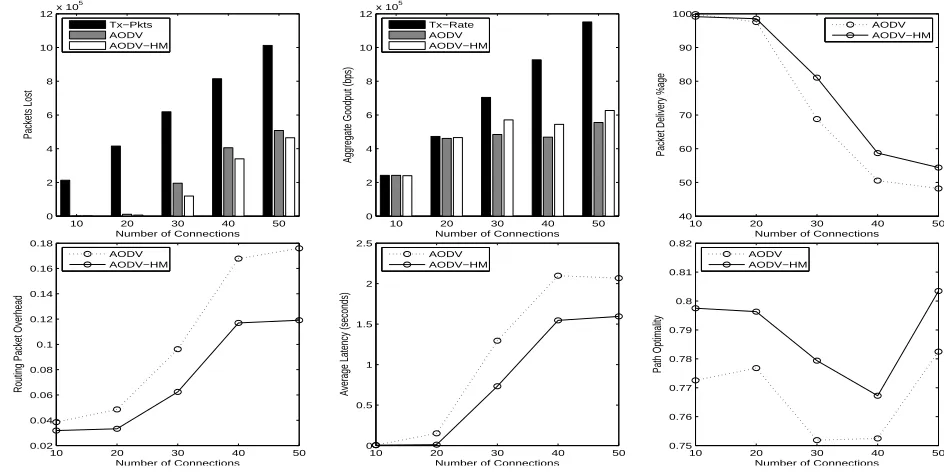
Figure 6: Results of Simulation 2
AODV-HM compared to standard AODV. This is pri-marily due to the selection of staticMESH ROUTERs in the routing process, which offer more stable routes with less contention. On the other hand, the stan-dard AODV has no option for prioritizing the
rout-ing accordrout-ing to the node type. Thus both the
MESH ROUTERs and MESH CLIENTs are randomly
se-lected in establishing a route. Routes consisting
mostly of single-radio MESH CLIENTs have a higher
packet loss due to the extended contention for the wireless medium, which can lead to saturated inter-face queues and packets being dropped. The routes
formed by AODV-HM may also involveMESH CLIENTs
in its paths, but their number is relatively smaller.
The lower number of MESH CLIENTs in the path
means improved utilization of the channel diver-sity and lower contention for the wireless medium. This in effect reduces the packet drop when the AODV-HM protocol is engaged. However, when the
MESH CLIENTs move at a higher speed, the routes are
frequently broken and recreated. Thus we see an in-crease in the number of packets lost with the inin-crease in the network mobility.
The number of packets lost in the network, due to collisions or saturation of interface queues, di-rectly influences the aggregate goodput of the net-work. AODV-HM shows improved goodput over stan-dard AODV for all speeds. Even though AODV-HM aims to route traffic through the MESH ROUTERs, at higher speeds the routes become extremely unstable due to the movement of the source, destination and intermediaryMESH CLIENTs. The packet delivery rate of AODV-HM ranges from 83% at zero mobility to almost 57% at a speed of 20 m/s. Nevertheless, the packet delivery of AODV-HM is consistently higher than for standard AODV.
AODV-HM has the ability to create more stable routes by preferably involving static MESH ROUTERs. This in turn reduces the number of route discov-eries in the network, thereby lowering the control packet overhead. In addition, as AODV-HM is able to achieve a higher packet delivery rate, the control packet overhead per received data packet is signif-icantly lower than for AODV. However, it should be noted that AODV-HM does not incur any addi-tional byte overhead, since the MR-Count and Rec-Chan fields occupy existing fields of the AODVRREQ
header. The average latency of the network using AODV-HM is considerably lower than that of the standard AODV at varying speeds. The lower latency highlights the success of AODV-HM’s route selection mechanism along with the dynamic channel assign-ment carried out during the route discoveries. As mentioned earlier, standard AODV selects the first incomingRREQ. However, the firstRREQto arrive does not necessarily arrive via the shortest path (in terms of the number of hops). Our simulations show that by
delaying theRREQs in AODV-HM, the chance of
dis-covering shorter paths is increased. This is shown in the path optimality metric, which shows that AODV-HM paths have higher path optimality, i.e. they are shorter.
5.2 Simulation 2 : Varying the Traffic Load
In Simulation 2, we varied the traffic load in the net-work by increasing the number of simultaneous
con-nections between the MESH CLIENTs from 10 to 50,
with an increment of 10 connections. Our results (Fig. 6) show that at lower traffic loads, the perfor-mance of AODV-HM is comparable to that of the standard AODV protocol. However, as the load is in-creased, the packet loss incurred by AODV increases significantly, thereby decreasing the goodput of the network. The packet delivery rate for both proto-cols stays close to 100% up to 20 concurrent connec-tions. Beyond this point, the packet delivery rate of both protocols starts to degrade. Since the routes
cre-ated by AODV-HM contain moreMESH ROUTERs than
those created using AODV, we see an improved per-formance of the former under increasing traffic loads, relatively to AODV. The routing packet overhead of AODV-HM also remains lower. The latency of the network increases with the increase in the traffic load due to increasing contention for the wireless medium by nodes operating on interfering channels. However, AODV-HM still manages to maintain a significant im-provement over AODV.
5.3 Simulation 3 : Varying the Number of
MESH ROUTERs
Interest-0 4 9 16 25
Number of Mesh Routers
Packets Lost
Number of Mesh Routers
Aggregate Goodput (bps)
0 4 9 16 25
Number of Mesh Routers
Packet Delivery %age
0 4 9 16 25
Number of Mesh Routers
Routing Packet Overhead
0 4 9 16 25
Number of Mesh Routers
Average Latency (seconds)
0 4 9 16 25
Number of Mesh Routers
Path Optimality
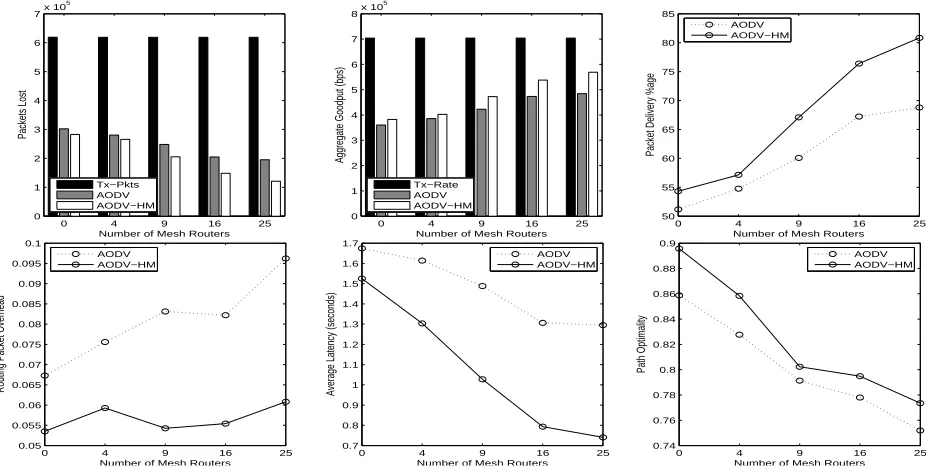
Figure 7: Results of Simulation 3
ingly, the results (Fig. 7) show that even when no
MESH ROUTER is present in the network, AODV-HM
still has a lower packet loss than standard AODV.
This is because AODV-HM delays the receivedRREQ
and responds to the one with the lowest hop count, since in this case MR-Count=0. In contrast, standard
AODV responds to the first RREQ that it received,
which may not necessarily have arrived via the short-est path, due to interference or contention on one of the links. This use of non-shortest paths in AODV increases the total load in the network and increases contention and packet loss. This is also confirmed by looking at the path optimality of AODV-HM, which is much closer to the shortest possible path5 than the paths created by AODV. The performance of both protocols improves with an increasing number
of MESH ROUTERs in the network. However,
AODV-HM makes more efficient use of theMESH ROUTERs and achieves an improved packet delivery rate, decreased packet overhead, and significantly lower latency.
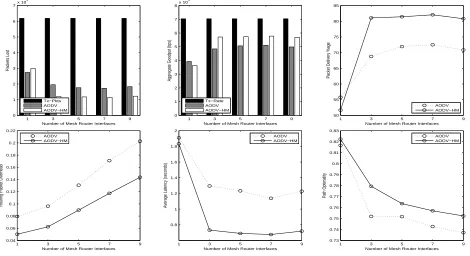
5.4 Simulation 4 : Varying the Number of
Radios on each MESH ROUTER
In Simulation 4, we varied the number of radio in-terfaces in eachMESH ROUTERfrom 1 to 9, with incre-ments of 2 interfaces. All channels have been config-ured to be orthogonal and non-interfering with each other. The results of Simulation 4 (Fig. 8) reveal that the only time standard AODV outperforms AODV-HM in terms of packet delivery rate is when all nodes are limited to a single radio operating on the same channel. This means that forcing packets to go via
MESH ROUTERs, when they do not have a higher
capac-ity than MESH CLIENTs, can have a slightly negative impact. In this particular case,MESH ROUTERs cannot take advantage of the channel diversity mechanisms of AODV-HM if they are equipped with only a sin-gle interface. Nevertheless, since the MESH ROUTERs are static, they provide more stable routes than
mo-bile MESH CLIENTs, which results in a reduced packet
overhead and lower latency in AODV-HM. The packet delivery rate rapidly improves when the number of
5
The shortest possible path is determined by an omniscient en-tity present in the NS-2 simulator known as the General Operations Director.
interfaces in theMESH ROUTERs is increased. AODV-HM significantly outperforms standard AODV in these scenarios. However, increasing the number of
MESH ROUTERinterfaces to more than three does not
show any further improvements. This is due to the fact that three interfaces operating on orthogonal channels are sufficient to provide the required capac-ity and channel diverscapac-ity for the network and traffic pattern considered in our simulation. However, the ideal number of MESH ROUTERinterfaces will vary for different types of networks with different size, density and traffic load. AODV-HM maintains its superior performance over the standard AODV protocol with the increase in the number of interfaces. It shows sig-nificantly lower packet overhead and latency, and a considerably better packet delivery ratio.
6 Conclusions
Hybrid WMNs consist of a mix of mobile
MESH CLIENTs and static MESH ROUTERs. These two
types of node differ considerably in terms of their capacity to forward packets. MESH ROUTERs are typ-ically much less resource constrained than mobile
MESH CLIENTs, and can be assumed to be equipped
with multiple radio interfaces. Current WMN rout-ing protocols do not differentiate between the types of node in a WMN, and are therefore not able to exploit the inherent heterogeneity in hybrid WMNs. In this paper, we presented simple extensions to the AODV routing protocol to increase its efficiency in hybrid WMNs. We defined a new routing metric that allows more efficient use of high capacity MESH ROUTERs by preferential routing of packets via paths traversing the
MESH ROUTERs. In addition, we integrated a channel
1 3 5 7 9
Number of Mesh Router Interfaces
Packets Lost
Number of Mesh Router Interfaces
Aggregate Goodput (bps)
Tx−Rate
Number of Mesh Router Interfaces
Packet Delivery %age
AODV
Number of Mesh Router Interfaces
Routing Packet Overhead
AODV
Number of Mesh Router Interfaces
Average Latency (seconds)
AODV
Number of Mesh Router Interfaces
Path Optimality
AODV AODV−HM
Figure 8: Results of Simulation 4
our proposed changes to the AODV protocol are very simple and incur only very minor additional overhead or complexity.
Acknowledgements
National ICT Australia is funded by the Australian Government’s Department of Communications, Infor-mation Technology, and the Arts and the Australian Research Council through Backing Australia’s Ability and the ICT Research Centre of Excellence programs and the Queensland Government.
References
Akyildiz, I. F. & Wang, X. (2005), ‘A Survey on
Wireless Mesh Networks’, IEEE
Communica-tions Magazine43(9), S23–S30.
Bianchi, G. (2000), ‘Performance Analysis of the IEEE 802.11 Distributed Coordination
Func-tion’, IEEE Journal on Selected Areas in
Com-munications18(3), 535–547.
Draves, R., Padhye, J. & Zill, B. (2004), Routing in Multi-Radio, Multi-Hop Wireless Mesh Net-works,in‘Proceedings of the 10th Annual Inter-national Conference on Mobile Computing and Networking’, ACM Press, pp. 114–128.
IEEE (1997), ‘Wireless LAN Medium Access Control (MAC) and Physical Layer (PHY) Specifications 802.11’.
Kyasanur, P. & Vaidya, N. H. (2006), ‘Routing and Link-layer Protocols for Channel
Multi-Interface Ad Hoc Wireless Networks’,
SIGMO-BILE Mobile Computing and Communications
Review10(1), 31–43.
Li, J., Blake, C., Couto, D. S. J. D., Lee, H. I. & Morris, R. (2001), Capacity of Ad Hoc Wire-less Networks,in‘Proceedings of the 7th Annual International Conference on Mobile Computing and Networking’, ACM Press, pp. 61–69.
NS (1989), ‘The Network Simulator’,
http://www.isi.edu/nsnam/ns/.
Perkins, C., Royer, E. M. & Das, S. (2003), ‘Ad hoc On-Demand Distance Vector (AODV) Routing’,
IETF RFC 3561.
Pirzada, A. A., McDonald, C. & Datta, A. (2006), ‘Performance Comparison of Trust-Based
Reac-tive Routing Protocols’, IEEE Transactions on
Mobile Computing5(6), 695–710.
Ramachandran, K., Buddhikot, M., Chandranmenon, G., Miller, S., Belding-Royer, E. & Almeroth, K. (2005), On the Design and Implementation of In-frastructure Mesh Networks, in ‘Proceedings of the IEEE Workshop on Wireless Mesh Networks (WiMesh)’, IEEE Press.
Raman, B. & Chebrolu, C. (2005), Design and Evalu-ation of a new MAC Protocol for Long-Distance
802.11 Mesh Networks, in ‘Proceedings of the
11th Annual International Conference on Mobile Computing and Networking (MobiCom)’, ACM Press, pp. 156–169.
Raniwala, A. & Chiueh, T. C. (2005), Architecture and Algorithms for an IEEE 802.11-based
Multi-Channel Wireless Mesh Network, in
‘Proceed-ings of the 24th Annual Joint Conference of the IEEE Computer and Communications Societies (INFOCOM)’, Vol. 3, IEEE Press, pp. 2223– 2234.
Royer, E. M. & Toh, C. K. (1999), ‘A Review of Cur-rent Routing Protocols for Ad hoc Mobile
Wire-less Networks’,IEEE Personal Communications
Magazine6(2), 46–55.