A Simple Technique to Determine Interface Slip of
Stud Connected SCC Girders
Prakash, A.1), Lakshmanan, N. 1), Anandavalli, N. 1), Madheswaran, C.K. 1), Iyer, N.R. 1), and Rajasankar, J. 1)*
Abstract: A simple technique is proposed to compute interface slip of stud connected steel-concrete composite (SCC) girders based on the results of a flexure test. The technique makes use of relative longitudinal displacement of the concrete slab and steel beam to calculate the interface slip. In the flexure test of a SCC girder, a cost-effective instrumentation arrangement consisting of mechanical dial gauges is used to measure the relative longitudinal displacement. Responses measured from experiments on SCC girders conducted by the authors are used for numerical implementation and validation of the technique. Alternatively, interface slip is also evaluated by applying an analytical model which is based on first principles of mechanics. The values of interface slip computed by using the proposed technique are found to have close correlation with those of the analytical model. The effect of edge restraint on slip due to friction between steel and concrete is also studied.
Keywords: Dial gauges, end correction, interface slip, slip strain, steel-concrete composite girder, stud connector.
Introduction
In the design of steel-concrete composite (SCC) structures, one of the important considerations is with regard to interface slip between concrete slab and steel beam. In addition to the design checks for serviceability criteria, evaluation of moment capa-city, deflection and failure modes due to partial-interaction behaviour of SCC girders are equally important [1,2]. Oehlers et al. [3] have analysed a SCC beam showing partial interaction even with full shear connection. It was reported that partial interaction reduces the strain in the steel element, due to which strain hardening benefits are com-promised at failure. However, they have suggested that the predicted slips should be compared with the experimentally measured values. It has been observed that to ensure reliability of the results obtained from numerical and analytical studies, there is always a need for standard experiment to supplement or complement such studies. On referring to the literature pertaining to the last five decades, it can easily be observed that there are number of studies on SCC girders, encompassing numerical, analytical and experimental domains.
1 CSIR-Structural Engineering Research Centre, CSIR Campus, Taramani, Chennai-600113, INDIA
* Corresponding author, email: [email protected]
Note: Discussion is expected before November, 1st 2012, and will be published in the “Civil Engineering Dimension” volume 15, number 1, March 2013.
Received 11 October 2011; revised 23 April 2012; accepted 20 July
Among the experimental studies, those conducted by Viest [4], Chapman and Balakrishnan [5] and Slutter and Driscoll [6] are extensively referred for validation by even recent analytical and numerical studies. However in those experimental studies, the main emphasis was only on measuring the load-deflection response.
Advanced analysis including nonlinear effects and probabilistic concepts are essential for accurate pre-diction of strength, and serviceability considerations [7-9]. Mostly, existing specifications are based on the assumption that ductility of the stud alone contri-butes to the deformation of the girder. However, interface slip has direct influence on the ductility as well as on flexural capacity of the SCC girder. For the measurement of interface slip, LVDTs (linear variable differential transformers) are most suitable and, therefore, are commonly used. For example, LVDTs are used to measure slip at the ends of pre-cracked stud connected SCC beam by Zurkiewiez and Braymand [10] and in composite steel-high strength concrete beam by Nie et al. [11]. Although a number of experimental studies has been reported in the existing literature, yet these studies were mainly focused on flexural behaviour including partial and full interaction between steel beam and concrete slab. Most of the reported experimental studies have used LVDTs for the measurement of interface slip.
suggested a simplified method for assessing the ductile behaviour of stud connectors in composite beams with high strength concrete and compared results with normal strength concrete. It has also been reported by them, that normal strength concrete presents a softening branch that enables high connection deformation versus reduced trans-mission of interface shear force. Connection beha-viour is reported as brittle when connector shank gets sheared off at a slip value close to the ultimate shear strength of connector.
This paper proposes a simple technique for the determination of interface slip in a SCC girder by using relative longitudinal displacement of the concrete slab and steel beam at the interface measured with mechanical dial gauges. The tech-nique has been applied to calculate the interface slip of the SCC girders on which experiments were conducted by the authors. For comparison purposes, interface slip is also calculated by using an alternate analytical model which is based on first principles of mechanics. The analytical model makes use of variation of slip-strain with bending moment at the centre of the span to evaluate the interface slip along the span. On comparison, the values of the interface slip are found to match with those values obtained from analytical model. The proposed technique is adaptive in terms of providing cost-effective solution by eliminating the need for LVDTs for determining the interface slip values. The contribution of the paper is the simple validated technique to determine interface slip of stud connected SCC girders. Basically in this study it is highlighted that the interface-slip can be measured by using mechanical dial gauges where no power supply is needed as compared to the case with LVDTs. In addition to this it is also emphasized that the interface slip can be derived using first principle along with the help of longitudinal strain variation across the depth at mid span of SCC girder for any given load. Authors consider that this study is the first one, in which the detailed procedure to compute the interface slip is provided and analytical results are validated with experimental results.
Motivation
Understanding of the interface behavior in the design of stud connected steel composite girders is an important step. In resisting the interface shear forces, studs act like dowels. The dowel action becomes effective only when the studs undergo deformation. In the design of SCC girder, the deflection is one of the serviceability criteria.
With development of sufficiently accurate models for prediction of end slip, it may also become one of the design criteria. In the context of present day trend towards using deformations for performance evalua-tion, the accurate evaluation of slip is indeed an important step. It is essential to have an idea about the expected slip for a given configuration of the girder and the loading. Due to bending, the interface between concrete slab and steel beam shows relative movement in longitudinal direction in SCC girders. Therefore in an experiment on SCC girders, it is vital to measure the slip as well as strength of interface connection. Typical steel and concrete elements of a SCC girder are shown in Figure 1.
In SCC girders, the shear connection significantly affects deformation and maximum bearing capacity, which is mostly realized by means of deformable studs. In these girders, shear develops at the interface between the slab and girder due to flexural loading. This induces relative displacement between the girder and slab, and is referred as interface slip which further causes partial interaction behaviour. Mechanism of force transfer in stud connected SCC girder is shown in Figure 2. It can be seen that with the increase in load, interface slip at the ends of simple supported girder also increases. Due to this, concrete in the vicinity of stud is subjected to high stresses as illustrated in Figures 2(b) and (c).
Proposed Technique
Instrumentation Set-up
Reinforced concrete slab
Strain distribution with finite interface slip
Steel beam Section at A-A
Steel-concrete interface
A A
Effective width of RC slab
Figure 1. Typical Simply Supported SCC Girder
Load W=0
Load W1
Load W2 >W1
High stress zones Steel beam
Stud connectors Reinforced concrete slab
Interface
(a)
(b)
(c)
Interface slip
Increased slip Deformed shear connectors
No slip
Figure 2. Flexural Behaviour of SCC Girder
Principle
Due to interface slip at a particular section of SCC girder, the perspex plates A and B can have differential displacement in longitudinal direction, while in vertical plane is the same (Figure 4). In this case the plate A, which is bonded through steel angle piece using epoxy resin to the soffit of concrete slab and plate B which is attached to steel beam move in same direction (due to curvature of same sign), however, with relatively different magnitude. This is due to the fact that both plates A and B are positioned at same section and therefore the rotation is also considered as the same in both, the girder and the slab. Both the dial gauge readings can be recorded with accuracy of the order of 0.001mm (least count of dial gauge) for each load increment. The dial gauge readings provide horizontal movement of plates A and B in a load step. Difference in the movement of plates A and B is a measure of the interface slip.
Issues Involved with Interface Slip Measurement
Two important issues may possibly arise when the load on the SCC girder is increased. First is due to vertical displacement of SCC girder. Due to this vertical displacement of the plates, the point of measurement for the horizontal displacement changes every time as shown in Figure 4. It means the tip of both dial gauge slides on the plate upward as the plates moves down due to increment in load.
One may think that if the point of measurement is not fixed than how the measurements can be accurate? Second issue is due to rotation of girder and the slab that can induce rotation of plates A and B in some cases. The proposed technique can effectively address both these issues as explained in following sections.
Effect of the vertical movement of SCC girder
As shown in Figure 4, dial gauges are mounted at specified location along the SCC girder on an independent supporting platform. Each specified section has been provided with two horizontally mounted dial gauges. Initially needles of the dial gauges were set in the midway of the maximum range. This was done to allow the dial gauge tip to move in both the directions (in and out) along with the movement of perspex plates A and B. Depending upon the load, these plates can move either way, therefore keeping the needle in mid way is recommended. Now if the plates A and B move down with deflected shape of girder, both the dial gauges DG1 and DG2 will be moving together. Since both the needles slide together on the perspex plates to a new position in vertical plane (Figure 4), influence of vertical deflection of SCC girder on the measured slip can be ignored. This issue does not arise in case of LVDTs because their base rest on steel beam flange which also move along with the reference plates such that point of measurement does not change.
Effect of the rotation of SCC girder at a section
The perspex plates A and B are pasted at the same longitudinal section on the bottom surface of the concrete slab and the girder flange (Figure 4). During bending, the plates may undergo differential rotation due to the difference in the levels of the bottom surface of the slab and flange. The measured longi-tudinal displacement may indicate an additionnal component due to this differential rotation. However, considering the normal values of flange thickness of a girder, it can be expected that the differential rotation values will be finite but negligible. In fact, the value has also been verified to be considerably small based on the results of numerical investiga-tions explained later. This issue is equally present in the measurement of slip using LVDTs, though the magnitude of differential rotation will be smaller because LVDTs can be mounted closer to the inter-face as compared to dial gauges.
Demonstration of the Proposed Technique
As a part of the present study, experiments were carried out on SCC girder to investigate their flexural behaviour. A series of six large-scale SCC girders were tested under monotonic (Quasi-static) and cyclic loading. Typical detailed schematic dia-gram of the test setup used in the experimental study is shown in Figure 5. The SCC girder
speci-mens were designed and tested for 100%, 85%, and 70% shear capacities.
Each girder specimen was 4 m long simply sup-ported over a span of 3.8 m. Besides the concrete slab, SCC girder comprises of rolled steel beam with workshop welded stud connectors and plate type stiffeners at the ends. The width of the concrete slab was 665 mm. The test setup was basically same for both quasi-static and cyclic loading. The tests were carried out after the concrete had achieved its design strength (36 MPa). A hydraulic actuator capable of applying up to a maximum load of 600 kN was used to test the specimens. Roller at one end of the specimen and rocker at the other end was used to ensure the simply supported end conditions. Load was applied by the actuator and distributed at two points through distributor beam assembly. SCC girder specimen was instrumented for measuring of vertical defections along the length, steel and con-crete strains at mid span, and the slip between concrete slab and steel beam. Cross-sectional details of SCC girder shape and size are shown in Figure 6 and the experimental set-up is illustrated in Figure 7.
For six beams, dial gauges were mounted to measure both vertical and longitudinal deflections. Concrete strains at quarter and mid span were also measured. During testing, the steel beam was examined for
w w
160 1600 600 1600 100
Stud connectors
lifiting hook
Bearing stiffener
All dimensions are in mm
L=3800
Reinforced concrete slab
Steel rolled beam section
Figure 5. Details of Steel-Concrete Composite Girder Specimen
665
All dimensions are in mm
Stud shear connectors Steel beam
Bearing stiffener
Reinforced concrete slab
15 clear cover 12 dia. rebar @100 c\c bothways 150
Figure 7. Experimental Test set up for Slip Measurement
yielding. Surface of concrete was continuously moni-tored for crack formation. Testing was terminated when crushing of the concrete occurred or the deflection became excessively large and crack width widened abruptly with increment in the loading. The load-displacement curves, interface slip, ultimate load and mode of failure were recorded for each SCC girder specimen.
Interface slip
Theoretically, maximum slip has to be realised at the support. However due to support influence, or influence of supports little reduction in slip has been observed under the experimental conditions. Similar variation due to support influence has also been reported in literature [7]. One possible reason for reduction in interface slip may be the development of longitudinal friction force which opposes the slip near support. Interface slip variation along span in SCC girder specimens with the increment in load is shown in Figure 8. Maximum interface slip between steel flange and concrete slab for SCC girder specimen having full shear capacity was obtained as 3.56 mm at about 600 mm from support. Variation of interface slip along the span shows reduction towards mid span. It can be observed that with the proposed technique, values of interface slip can be calculated till the failure of the specimen.
Validation
In order to validate the proposed technique, interface slips have also been computed independently using an alternate method based on an analytical model. studied. The procedure followed in the derivation of the interface slip with the help of strain data is
0 400 800 1200 1600 2000 Distance from support (mm)
In
0 400 800 1200 1600 2000
Distance from support (mm)
Figure 8. Variation of Interface Slips Along Span
Derivation of Interface Slip from Longitudinal Strain Profile at Midspan
Following procedure has been adopted for the deriving the interface slip using strain data at the mid span. The accuracy of these derived slip is directly dependent on the recorded strain values. a. Corresponding to different load stages, the
CGS-1
-2500 0 2500 5000 7500 10000
Strain (microstrain)
-2000 0 2000 4000 6000 8000 10000
Strain (microstrain)
-2000 0 2000 4000 6000
Strain (microstrain) moment at mid span is obtained using the strain data at mid span (Figure 9), for three SCC girder specimens as shown in Figure 10. It can be seen that bending moment versus slip strain curves for specimen CGS-2 and CGS-3 are nearly matching at mid span. Therefore the typical comparisons are depicted only for specimen CGS-1 and CGS-2. However exactly same procedure can be followed to compute for any girder specimen. From these curves (Figure 10) the slip strain at various sections of the girders are computed by interpolation for the known
section-0
0 0.001 0.002 0.003 0.004
Slip strain
Figure 10. Bending Moment vs Slip Strain at Mid Span
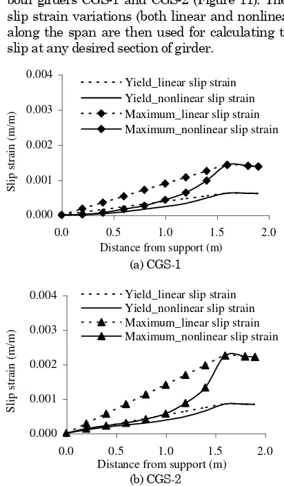
c. The slip strain in the constant bending moment zone corresponds to the value of slip strain for a given moment. Two analytical procedures are considered to compute the slip strain variation. In the first procedure the slip strain variation is considered to be linear between support and load point (i.e. assumed to give upper bound values of interface slips). In the second case, nonlinear slip strain variation as obtained from analysis is considered. The value of slip strain was taken as that corresponding to the bending moment at the section. The exercise is repeated for the load value near yield stage and maximum capacity of both girders CGS-1 and CGS-2 (Figure 11). These slip strain variations (both linear and nonlinear) along the span are then used for calculating the slip at any desired section of girder.
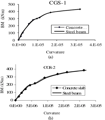
d. The variations in curvatures for concrete slab and steel beam at centre of the beam with applied bending moment for CGS-1 and CGS-2 are shown in Figure 12. The curvatures in concrete and steel are found to be nearly same. However for exactness, the difference between the curva-tures of concrete slab and steel girder is plotted as shown in Fig 13. Using the curves in Figure 13 the differential rotations between the concrete slab and steel beam at different sections (where the slip dial gauges were located), are calculated using first principles. The differential rotation multiplied by the offset distance of dial gauge tip from the slab and girder interface is the correction to be applied for slip at the section under consideration. Though these values are found rather small of the order of 0.01 to 0.07 mm, these are used to suitably correct the measured interface slips obtained experimentally as shown in Figure 14. This same process was repeated for various girder sections of CGS-1 and CGS-2, and the corrected experimental values of the interface slip along the span corresponding to yield load (Figure 14 (a)) and maximum loads (Figure 14 (b)) are obtained. It can be observed that the measured interface slip values exhibit close corroboration with the derived values based on linear slip strain variation along the span of SCC girder. However for different strength of stud, the values of the interface slip may lie between the derived values corresponding to linear and nonlinear slip strain variation along span, depending upon the degree of partial
0.E+00 1.E-05 2.E-05 3.E-05 4.E-05
B
0.E+00 5.E-06 1.E-05 2.E-05 2.E-05 3.E-05
BM
Figure 12. Curvature Variation with Bending Moment at Mid Span
Figure 13. Variation of Bending Moment with Difference in Curvature at Mid Span
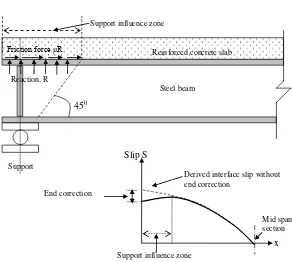
e. The values of interface slip shown in Figs. 14 (a) and (b) obtained from the proposed technique show some reduction near the support. The reason for this reduction is the enhanced frictional resistance between the slab and girder near the support. Since the slab is relatively rigid with respect to shear deformation, and also has high shear capacity, the bearing stiffener trans-fers the support reaction to the bottom of the slab. This introduces longitudinal force at an eccentric-city of half the slab thickness which results in frictional resistance as shown in Figure 15. Based on equilibrium conditions, the expression given in Eqn. (1) is proposed for the end correction to
where, Send is corrected interface slip value at the
end, Smax is maximum interface slip value at the
end without correction, μ is coefficient of friction between concrete and steel, R is reaction due to load, Ac is area of slab in contact with steel, Ec is
Young’s modulus of elasticity for concrete and d is width of support influence zone. The factor 4 is obtained from the consideration of the expected stress distribution at the interface due to the frictional force. The expression in Eqn. (1) is applicable to the support influence zone which can be approximated by the influence line drawn at 45 degrees at support as shown in Figure 15. Therefore the analytically derived values of interface slips are corrected for the above mentioned support influence and plotted in Figures 14(a) and (b).
0.0 0.5 1.0 1.5 2.0
0 500 1000 1500 2000
Distance from support (mm)
Int
er
fa
ce
sl
ip
(mm
)
CGS-1 (Derived_nonlinear slip strain variation) CGS-2 (Derived_nonlinear slip strain variation) CGS-1 (Derived_linear slip strain variation) CGS-2 (Derived_linear slip strain variation) CGS-1_Experimental corrected
CGS-2_Experimental corrected
(a) Near yield load (360 kN)
0.0 1.0 2.0 3.0
0 500 1000 1500 2000
Distance from support (mm)
Inte
rfac
e s
lip (m
m)
CGS-1 (Derived_nonlinear slip strain variation) CGS-2 (Derived_nonlinear slip strain variation) CGS-1 (Derived_linear slip strain variation) CGS-2 (Derived_linear slip strain variation) CGS-1_Experimental corrected
CGS-2_Experimental corrected
(b) Near maximum load (480 kN)
Figure 14. Interface Slip Variation Along Span
Friction force μR
Reaction, R
Support
450
Steel beam
Reinforced concrete slab Support influence zone
Mid span section
x Slip S
End correction
Derived interface slip without end correction
Support influence zone
Conclusions
A simple technique has been proposed to determine interface slip of SCC girders subjected to flexural loading. The technique employs mechanical dial gauges along the span of SCC girder. The technique has been implemented and used to calculate the slip of SCC girders in an experiment. As an alternative, it is shown that the interface slip values can also be derived from the longitudinal strain variation along depth of the girder at mid span. The interface slip values obtained based on the proposed technique is found to compare well with those derived from the mid span strain data and also exhibit close corrobo-ration with the bending moment diagram. However, studs having lower yield strength may show some variation along the span of girder in between the bounds corresponding to linear and nonlinear slip strain variation. An explanation for the reduction in the interface slip near the support has been provided. In addition, an expression to evaluate the end correc-tion is also proposed. Authors strongly consider that the proposed technique will be very useful in enhanc-ing the capability of researchers who can afford to only cost-effective mechanical dial gauges in lieu of expensive LVDTs for instrumentation in a flexural experiment on SCC girders.
Acknowledgements
The authors acknowledge the help received from the staff of Advanced Material Laboratory and Struc-tural Testing Laboratory, in conducting the experi-mental study. This paper is being published with the kind permission of Director, CSIR-Structural Engi-neering Research Centre, Chennai, INDIA.
References
1. Fam, A., MacDougall, C., and Shaat, A., Upgrad-ing Steel–Concrete Composite Girders and Repair of Damaged Steel Beams using Bonded CFRP Laminates, Thin-Walled Structures, 47(10), 2009, pp. 1122-1135.
2. Jeong Y.J., Kim, H.Y. and Kim, S. H., Partial Interaction Analysis with Push-out Tests,
Journal of Constructional Steel Research, 61(9), 2005, pp. 1318-1331.
3. Oehlers, D. J., Nguyen, N.T., Ahmed, M., and Brad-ford, M.A., Partial Interaction in Composite Steel and Concrete Beams with Full Shear Connection,
Journal of Constructional Steel Research,
41(2-3), 1997, pp. 235-248.
4. Viest, I. M., Investigation of Stud Shear Connec-tors for Composite Concrete and Steel T-beam, Journal of American Concrete Institute, 52(4), 1956, pp. 875-891.
5. Chapman, J. C. and Balakrishnan, S., Experi-ments on Composite Beams, Structural Engi-neering, 42(11), 1964, pp. 369-383.
6. Slutter R. G. and Driscoll, G. C., Flexural Strength of Steel-Concrete Composite Beams, Journal of Structural Division, ASCE, 91(ST-2), 1965, pp. 71-99.
7. Ayoub, A., A Force Based Model for Composite Steel-Concrete Beams with Partial Interaction,
Journal of Constructional Steel Research, 61(3), 2005, pp 387-414.
8. Zona, A., Barbato, M., Asta, A.D., and Dezi, L., Probabilistic Analysis for Design Assessment of Continuous Steel–Concrete Composite Girders,
Journal of Constructional Steel Research, 66(7), 2010, pp. 897-905.
9. He, J., Liu, Y., Chen, A., and Yoda, T., Experi-mental Study on Inelastic Mechanical Behaviour of Composite Girders under Hogging Moment,
Journal of Constructional Steel Research, 66(1), 2010, pp. 37-52.
10.Zurkiewiez, B. and Braymand, S., Experimental Study of a Pre-Cracked Steel-Concrete Beam,
Journal of Constructional Steel Research, 63(1), 2007, pp. 135-144.
11.Nie, J., Xiao, Y., Tan, Y., and Wang, H., Experi-mental Studies on Behaviour of Composite Steel High-Strength Concrete Beams, ACI Structural Journal; 101(2), 2004, pp. 245-251.
12.El-Lobody, E., Performance of Composite Girders Strengthened using Carbon Fibre Reinforced Polymer Laminates, Thin-Walled Structures, 49(11), 2011, pp. 1429-1441.
13.Larbi, A.S., Ferrier, A., and Hamelin, P., Con-crete to Steel Lap Joint Failure Criteria Under Combined Shear and Peeling Stress, Journal of Constructional Steel Research, 65(2), 2009, pp. 386-394.