64:4 (2013) 131–135 | www.jurnalteknologi.utm.my | eISSN 2180–3722 | ISSN 0127–9696
Teknologi
On-Site Partial Discharge Monitoring System in Generator at Tanjung Bin
Power Plant, Johor, Malaysia
A. H. Muhamada, Y. Z. Ariefb*, W. A. Izzatib, Z. Adzisb, M. A. B. Sidikb
aTanjung Bin Power Plant, Jalan Tanjung Bin, 82300 Kukup, Johor, Malaysia
bInstitute of High Voltage and High Current, Faculty of Electrical Engineering, Universiti Teknologi Malaysia, 81310 UTM Johor Bahru, Johor, Malaysia
*Corresponding author: [email protected]
Article history
Received :15 February 2013 Received in revised form : 10 June 2013
Accepted :16 July 2013
Graphical abstract
Abstract
Power generation is a business that ought to satisfy industrial and consumer electrical power needs. Power generation technology has emerged from conventional power plants, which are mostly steam power plants, evolving into more complicated nuclear power plants. While the mechanical arrangements in the power plants are usually unique and distinct from one another, their electrical assemblies are almost the same; the major factor considered is sizing of the electrical equipments. The electrical generator is therefore one of the fundamental equipment that every power plant must have. In principle, the generator is crucial equipment that needs proper maintenance in order to produce steady output supply. The objective of this study is to is to conduct on-site partial discharge monitoring system of 3 unit generators stator winding at Tanjung Bin Power Plant, Johor, Malaysia as condition based monitoring (CBM) system. Partial discharge characteristics of unit 10, 20 and 30 generators stator winding were compared respectively. Software designed by Iris LP was used throughout these processes. The software-PDView
demonstrates graphical view of the partial discharge occurrence in the generator stator winding. Compiled data were analyzed using Microsoft Excel in order to establish an evaluation of the generator stator winding. The analyzed results showed that all generators were in good condition.
Keywords: Generator; partial discharge; PDView software; generator stator winding Abstrak
Penjanaan kuasa adalah satu perniagaan yang kedua-duanya memenuhi keperluan industri dan pengguna. Teknologi penjanaan kuasa telah muncul dari loji janakuasa konvensional yang dilambangkan dengan loji stim konvensional dan berkembang sehingga ke loji nuklear. Sementara pengaturan mekanikal biasanya unik dan berbeza daripada sebuah loji jana kuasa berbanding dengan yang lain, pemasangan elektrik adalah hampir sama. Kebanyakan faktor adalah jangkaan pensaizan peralatan elektrik. Antara peralatan asas yang mesti dilengkapi dalam loji kuasa adalah penjana elektrik. Pada dasarnya, penjana adalah peralatan penting yang memerlukan penyelenggaraan yang sewajarnya untuk menghasilkan aliran output yang stabil. Objektif kajian ini adalah untuk mengkaji ciri-ciri nyahcas separa 3 unit penjana stator gegelung di Loji Jana Kuasa Tanjung Bin, Johor, Malaysia. Ciri-ciri nyahcas separa penjana gegelung stator unit 10, 20 dan 30 dibandingkan. Perisian yang direka oleh Iris LP akan digunakan sepanjang proses ini. Perisian PDView menunjukkan gambaran grafik berlakunya nyahcas separa dalam gegelung stator penjana. Data yang dikumpul dianalisis menggunakan Microsoft Excel untuk membuat penilaian terhadap gegelung stator penjana. Keputusan analisis menunjukkan bahawa semua penjana berada dalam keadaan yang baik.
Kata kunci: Penjana; nyahcas separa; perisian PDView; gegelung stator penjana
© 2013 Penerbit UTM Press. All rights reserved.
1.0 INTRODUCTION
As a rule of thumb, when a conductor is moved across a magnetic field or vice versa, electric current is generated inside the conductor. A generator produces electricity; whenever some mechanical force initiates the shaft or armature to spin, electricity is generated. Generator is the heart of electricity production where
pure electrical reactions occur and effectively produce massive amount of currents that is beneficial for industrial and home uses. Competent electricians are aware of the role played by a generator in the power generation business. A generator must be well kept, maintained and monitored. Some of the periodic maintenance activities that should be carried out include carbon brush measurement, slip ring cleaning and shaft voltage cleaning.
These activities are normally carried out on monthly basis or during shutdown.
Failure to do a proper maintenance could result in devastating failures. All maintenance histories are documented and audited periodically. While all these kind of maintenances are performed on generators, there is one more maintenance action that should be taken into consideration. Partial discharge in stator winding is a kind of slow deterioration process occurring on winding insulation. Measurements of the partial discharge in stator winding could be done on-line or off-line.
Reliable performances of generators are important key to profitable generation and transmission of electric power. Consequently, generator preventive maintenance can lead to system efficiency that will guarantee achieving uninterrupted power supply. The most updated tool to measure partial discharge in stator winding of a generator is an on line partial discharge monitoring system. This system will sense deterioration of winding insulation in the form of voltage sensed by Stator Slot
Coupler (SSC) that is installed in the generator2.
However, there might be interference signals that will distort the desired signal of partial discharge. Thus, the system was
designed with the ability to filter out unwanted signals2. Partial
discharge data that were measured and stored in designated computer through another monitoring system can be graphically demonstrated. Tabulation of data can be downloaded and analyzed further using Microsoft Excel.
Studies have shown that most stator windings are about 95%
reliable at any given time4. With this knowledge, it is important
for users of large generators to know or at least have an idea if any of their generators is one of the 5% that is not reliable. There are advantages of knowing that there are no problems. Some machines are known to be more reliable than others because of their design and how they are operated. However, these machines will eventually fail for reasons that include gradual thermal aging of the stator winding insulation. Users of the partial discharge test system will have the ability to detect early problems on-line and also identify the generators that are in good condition thus enabling them to be extended for longer operating times between major outages.
2.0 METHODS
Partial discharge data can be collected using many different techniques, the important criteria for any measurement made during normal generator operation is the ability to filter electrical interference or noise. When the generator is in operation and connected to the power system, many sources of noise are present including power system corona, slip ring sparking, poor electrical connections external to the stator winding, local power tool or arc welding equipment operation, and many more. All of these can generate pulses with characteristics similar to partial discharge, which can often be in orders of magnitude larger than the actual
partial discharge levels in the winding5. Without techniques to
eliminate these noise sources, on line partial discharge measurements made can lead to the wrong conclusion that the stator winding has deteriorated when the fact may not be so. Such false indications can reduce the credibility of on-line partial discharge testing. Thus, it is critical that any on-line measurement technique include methods to separate noise from partial discharge. A modern partial discharge measurement system is able to accomplish this, and thus provide an objective and reputable indication of the stator winding condition in the high-speed generators that are used in industrial facilities.
This study will focus on the predominant on-line partial discharge measurement technique in use today. It detects the voltage pulse
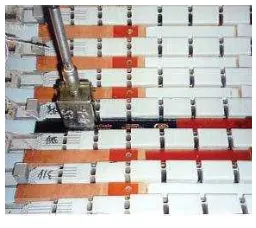
that is created when a partial discharge occurs via either a high voltage capacitor connected to the machines stator winding or a SSC (which is a type of antenna installed in stator slots). Figure 1 is a sample of SSC installed in on line partial discharge system.
Figure 1 Stator slot couplers (SSC)5
SSCs are high frequency sensors used to detect partial discharges in stator windings in operating gas or steam turbine generators that generate more than 100 MVA. One coupler-per-phase parallel circuit is generally recommended as a minimum to provide basic winding coverage. This criteria results in the installation of six SSCs in most generators and large motors, since most of these generators are often wound with two circuits per
phase5. SSCs are installed either beneath the wedge or between
bars outside of the semi-conductive surface of the stator winding
insulation system as shown in Figure 2.
Figure 2 Typical SSC installations5
Each generator monitored requires a Data Acquisition Unit
(DAU) to be installed nearby and within 30 cm of the PD termination box. Appropriately sized coaxial cables connect the
PD termination box to the DAU5. The DAU measures the filtered
Figure 3 DAU unit5
One system controller can control multiple DAUs, usually over a dedicated LAN. The system controller has a PDGuardPro software, which instructs each DAU under what conditions to measure the partial discharges activity. For each DUA, operators can use a System Controller to define the machine operating condition and frequencies at which partial discharge measurement should be made. There is also facility for continuously measuring and monitoring of partial discharge activities at each DAU in order to raise an alarm whenever the partial discharge activity goes above a defined threshold; thus a program displaying and trending any saved partial discharge data. The system controller is usually a rack-mounted controller installed in an enclosed cabinet in a climate-controlled room. DAU unit is connected to System Controller via LAN network as shown in Figure 4.
Figure 4 DAU and system controller connection5
3.0 RESULTS AND DISCUSSION
Partial discharges plots were obtained from system controller. The graphs were generated using PDView Software provided by Iris Power. Each graph consists of bipolar slot total and bipolar endwinding. Generator Unit 10, 20 and 30 are equipped with six sensors per unit. They are named RS40, YS8, BS24, RS9, YS25 and BS4, respectively. Every sensor is positioned at 30, 150, and 270 degree according to the respective phases. For the ease of analysis, we group the sensors into two groups. The first group is denoted by RS40-YS8-BS24 and the latter would be RS9-YS25-BS41. Examples of bipolar slot total and bipolar endwinding were shown in Figure 5 and Figure 6, respectively.
In order to establish a 5-year trending for respective unit, three measurements per year for every unit were taken. Measurements were therefore taken in January, June and December each year for every unit for five consecutive years. All measurements taken were from 2007 until 2011. Somehow, not all months are available within the data range. The unavailable data that is missing due to anonymous problem was replaced with nearest month available. Clarification will be made in the affected
unit. From graphs generated by PDView software, we tabulated the maximum PD occurrence of each graph. The trending was plotted using Microsoft Excel and illustrated further in the respective section.
Figure 5 Bipolar slot total
Figure 6 Bipolar endwinding
Throughout five years, we obtained eighty-percent measurements that followed our default time of measurement namely January, June, and December for each year. Slight changes were done on measurement on June 2010, June 2011, and December 2011. The data were replaced with July 2010, May 2011, and November 2011, respectively. However, the plotted graphs denoted default date as January, June, and December. For example, red phase graph for Generator Unit 10 were illustrated in Figure 7 and Figure 8, respectively. Table 1 describes the figures illustrating results of PD pulse magnitudes of all generators.
Table 1 Figure numbers of respective generators and sensor group
Figure
number Generator Sensor Group Figure 9
Unit 10 RS40-YS8-BS24
Figure 10 RS9-YS25-BS41
Figure 11
Unit 20 RS40-YS8-BS24
Figure 12 RS9-YS25-BS41
Figure 13
Unit 30 RS40-YS8-BS24
Figure 7 Sensors RS40 Bipolar Slot Total
Figure 8 Sensors RS40 Bipolar Endwinding
Figure 9 Maximum PD Pulse Magnitude for Generator Unit 10 (RS40-YS8-BS24)
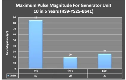
Figure 10 Maximum Pulse Magnitude for Generator Unit 10 (RS9-YS25-BS41)
Figure 11 Maximum PD Pulse Magnitude for Generator Unit 20 (RS40-YS8-BS24)
Figure 12 Maximum PD Pulse Magnitude for Generator Unit 20 (RS9-YS25-BS41)
Figure 13 Maximum Pulse Magnitude for Generator Unit 30 (RS40-YS8-BS24)
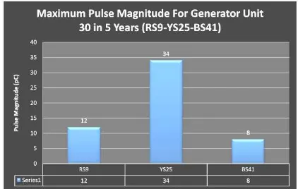
Results of the current test should be compared to any previous test results. Trending of the pulse magnitude will give an indication of the progression of the aging mechanism. The doubling of PD activity every six months will be strong indicator that shows rapid development in the mechanism failure. Aging is a very slow process and sudden changes are not expected in the PD test results. Comparison is likely to be made if the unit operating parameters like voltage, load, winding temperature and gas pressure are similar to those of the previous test. Typical PD life cycle of an asset on a new machine will often start relatively high and then decrease as the winding settles over 12-18 months
to “baseline” levels. The following should be many years of
Figure 14 Maximum Pulse Magnitude for Generator Unit 30 (RS9-YS25-BS41
4.0 CONCLUSION
Generator age has been shown to not be the determining factor for winding condition. More modern windings do not necessarily have more reliable insulation, implying that time-based maintenance practices may not be optimal for large generators. The time to winding failure is normally the result of a deteriorated winding being subjected to an extreme stress such as a lightning strike, out-of-phase synchronization, excessive starts, or system imbalance. As these events are unpredictable, it is impossible to forecast when a failure will occur. However, by monitoring the partial discharge characteristics of a stator winding, it is often possible to determine which machines are more susceptible to failure and therefore which require maintenance.
The partial discharge characteristic of Generator Unit 10, Generator Unit 20 and Generator Unit 30 stator windings had been carried out in this research project. The evaluation of generator unit 10, Generator Unit 20 and Generator Unit 30 had been performed in term of partial discharge trend. Our assessment shows that there are no reasons to restrict the operation of these units or to initiate any special considerations for stator maintenance. Regular review and analysis of the test result is recommended in order to monitor any discharge levels in the course of time.
Acknowledgement
The author would like to thank the management of Tanjung Bin
Power Plant (TBPP) for the use of facilities to complete this research project.
References
[1] IEEE Power Engineering Society. 2000. IEEE Trial-Use Guide to the Measurement of Partial Discharges in Rotating Machinery. IEEE. [2] Iris Power, L. P. On-Line Partial Discharge Testing for Motors &
Generators.
[3] Iris Power, L. P. Interpretation of PD Results: On-line Testing Using Capacitive or Stator Slot Couplers.
[4] G.C. Stone and Vicki Warren. Practical Experience with On-Line Partial
Discharge Condition Monitoring of Stator Windings. Iris Power, 1 Westside Drive, Unit 2, Toronto, M9C 1B2 Canada.
[5] TgBin-TSB-B7-B-09710_O&M Manual 7-10 Partial Discharge