BACHELOR THESIS – ME 141502
SELECTION OF TURBOCHARGERS ON DYNAMIC MAIN ENGINE
OPERATING CONDITIONS
Muhammad Suryo Panotogomo Abi Suroso NRP. 4213 101 021
Supervisor :
Beny Cahyono, ST., MT., Ph.D
Co-Supervisor :
Ir. Aguk Zuhdi Muhammad Fathallah, M.Eng, Ph.D
DOUBLE DEGREE PROGRAM OF MARINE ENGINEERING DEPARTMENT FACULTY OF MARINE TECHNOLOGY
INSTITUT TEKNOLOGI SEPULUH NOPEMBER SURABAYA
2017
SKRIPSI – ME 141502
PEMILIHAN TURBOCHARGER PADA DYNAMIC MAIN ENGINE OPERATING
CONDITIONS
Muhammad Suryo Panotogomo Abi Suroso NRP. 4213 101 021
DOSEN PEMBIMBING :
Beny Cahyono, ST., MT., Ph.D
Ir. Aguk Zuhdi Muhammad Fathallah, M.Eng, Ph.D
PROGRAM DOUBLE DEGREE
DEPARTEMEN TEKNIK SISTEM PERKAPALAN FAKULTAS TEKNOLOGI KELAUTAN
INSTITUT TEKNOLOGI SEPULUH NOPEMBER SURABAYA
2017
iv
vi
viii
ix DECLARATION OF HONOUR
I, who signed below hereby confirm that:
This final project report has written without any plagiarism act, and confirm conclously that all the dates, concepts, design, references, and material in this report own by Marine Power Plant Laboratory (MPP) in Department of Marine Engineering ITS which are the product of research study and reserve the right to use for further research study and its development.
Name : Muhammad Suryo Panotogomo Abi Suroso
NRP : 4213 101 021
Bachelor Thesis Title : SELECTION OF TURBOCHARGERS ON DYNAMIC MAIN ENGINE OPERATING CONDITIONS
Department : Marine Engineering
If there is any plagiarism in the future, I will fully responsible and receive the penalty given by ITS according to the regulation applied.
Surabaya, July 2017
x
xi
Selection of Turbochargers on Dynamic Main Engine Operating Conditions
Student : Muhammad Suryo Panotogomo Abi Suroso NRP : 4213 101 021
Department : Double Degree Program of Marine Engineering Supervisor : Beny Cahyono, ST., MT., P h.D
Ir. Aguk Zuhdi Muhammad Fathallah, M.Eng, Ph.D
ABSTRACT
Every turbocharger has differences efficiency of its working area, it has to be considered seriously because in every volumetric flow rate and pressure ratio turbocharger has different efficiency. Moreover in dynamic main engine operating conditions the various speed of ship is influencing the process of thermodynamics in main engine combustion chamber. The value of pressure ratio and temperature of air supply is relying to its process. MV. Meratus Palembang as a container ship has a dynamic main engine operating conditions to deliver its cargo on time. Based on Grinevetsky Mazing Method, thermodynamics process can be calculated into four main steps; charging, compression, combustion, and expansion. The approach are used to obtain the value of turbocharger operating line, turbocharger efficiency, and engine power output which are the parameter for turbo-engine matching. In the engine-propeller load, at maximum pressure ratio of turbocharger have a volumetric flow rate at 3,15 m3/s for VTR 304, for VTR 321 at 2,5 m3/s, and for VTR 354 also at 3,15 m3/s. These things happen because propeller given a high loads to the engine which affecting turbocharger to support more energy than the engine normal load. So the dynamic main engine operating conditions make the volumetric value increasing. Moreover on VTR 304 at 11,1 knots turbocharger has an efficiency at 80%, and for design speed of ship (Vs) at 10,4 knots turbocharger has an efficiency at 78%, on VTR 321 at 11,1 knots turbocharger has an efficiency at 78 % and for design speed of ship (Vs) at 10,4 knots turbocharger have an efficiency at 80%, on VTR 354 at 11,1 knots turbocharger is surging and for design speed of ship (Vs) at 10,4 knots turbocharger have a surge efficiency also. Engine power output at maximum load condition for VTR 304 the power output become 3220,595 kW, for VTR 321 become 2588,903 kW, and for VTR 354 become 3220,595 kW.
Keywords – Diesel Engine, Engine-Propeller Turbo matching, Turbocharger
xii
xiii
Pemilihan Turbocharger pada Dynamic Main Engine Operating Conditions
Nama : Muhammad Suryo Panotogomo Abi Suroso
NRP : 4213 101 021
Departemen : Teknik Sistem Perkapalan Program Double Degree Dosen Pembimbing : Beny Cahyono, ST., MT., P h.D
Ir. Aguk Zuhdi Muhammad Fathallah, M.Eng, Ph.D
ABSTRAK
Setiap tipe turbocharger memiliki perbedaan efisiensi, karena turbocharger sangat dipengaruhi oleh nilai volumetric flow rate dan compression ratio yang berubah-ubah tergantung pada kondisi kinerja mesin. Terutama pada dynamic main engine operating conditions, perubahan kecepatan kapal mempengaruhi proses termodinamika pada ruang bakar mesin. Nilai compression ratio dan suplai temperatur udara bergantung pada prosesnya. MV. Meratus Palembang
sebagai kapal kontainer bekerja pada “dynamic main engine operating conditions” untuk mengantarkan muatan secara tepat waktu. Berdasarkan Grinevetsky Mazing Method, proses termodinamika dapat dihitung menjadi empat bagian utama; charging, compression, combustion, dan expansion. Metode ini dipergunakan untuk mendapatkan nilai turbocharger operating line, turbocharger efficiency, dan engine power output dimana nilai-nilai tersebut merupakan parameter dari turbo-engine matching. Efek pembebanan mempengaruhi nilai volumetric flow rate 3,15 m3/s untuk VTR 304, untuk VTR 321 2,5 m3/s, dan untuk VTR 354 juga pada 3,15 m3/s. Hal ini terjadi karena mesin diberi beban yang tinggi oleh propeller yang akan mempengaruhi kinerja turbocharger untuk meberikan energi lebih. Sehingga pada dynamic main engine operating conditions membuat nilai volumetric flow rate semakin meningkat. Selain itu pada VTR 304 di kecepatan kapal 11,1 knot turbocharger memiliki efisiensi sebesar 80%, dan keceptan dinas (Vs) di 10,4 knot turbocharger memiliki efisiensi sebesar 78%, pada VTR 321 di kecepatan 11,1 knot turbocharger memiliki efisiensi sebesar 78% dan pada keceptan dinas (Vs) di 10,4 knot turbocharger memiliki efisiensi sebesar 80%, pada VTR 354 di keceptan 11,1 knot turbocharger bekerja secara surging dan kecepatan dinas(Vs) pada 10,4 Knot turbocharger juga bekerja secara surging. Daya mesin pada kondisi beban maksimum untuk VTR 304 menjadi 3220.595 kW, untuk VTR 321 menjadi 2588.903 kW, dan untuk VTR 354 menjadi 3220.595 kW.
Keywords – Diesel Engine, Engine Propeller-Turbo matching, Turbocharger
xiv
xv PREFACE
Alhamdulillahirobbil „alamin. Praise is merely to the Almighty Allah SWT for the gracious mercy and tremendeous blessing which enables the author to accomplish this bachelor thesis.
This thesis report entitled “Selection Of Turbochargers On Dynamic Main Engine Operating Conditions” is submitted to fulfill one of the requirements in accomplishing the bachelor degree program at Marine Engineering Department, Faculty of Marine Technology, Institut Teknologi Sepuluh Nopember Surabaya. Conducting this research study is not possible without all helps and supports from various parties. Therefore, the author would like to thank to all people who has support the author for accomplishing this bachelor thesis, among others:
1. First, to my parents, Mr. Joko santoso abi suroso and Mrs. Kristiwi natalia who always give their support, prayers, assistances and encouragements for every single path the author chooses also to my beloved brother and sister that always remembering me to keep fight until my bachelor thesis is completed.
2. Department of Marine Engineering Management who has guided and giving path to do the bachelor thesis till finished
3. Beny Cahyono, ST., MT., P h.D as Author’s thesis supervisor and the Head of MPP Laboratory who has provided huge advise as long as author writes this bachelor thesis.
4. Mr. Ir. Aguk Zuhdi Muhammad Fathallah, M.Eng Ph.D as author’s lecturer
advisor and author’s thesis co-supervisor who has provided huge knowledge and motivation.
5. Mr. Ir. Dwi Priyanta, MSE as Double Degree of Marine Engineering Secretary who has advised provided beneficial advisory and motivation.
6. Mr. Ditrayi, who support me collecting specifcations data of turbocharger and give an advise to completing my bachelor thesis.
7. Mr. Fahru, who support me collecting engine logbook and specifications of main engine data.
8. All of my friends particularly BARAKUDA 2013 who had help, cooperate, and support the author to do the bachelor thesis until finish.
xvi
xvii
LIST OF CONTENT
APPROVAL FORM ... iii
APPROVAL FORM ... v
APPROVAL FORM ... vii
DECLARATION OF HONOUR ... ix
ABSTRACT ... xi
ABSTRAK ... xiii
PREFACE ... xv
LIST OF CONTENT ... xvii
LIST OF FIGURES ... xix
LIST OF TABLES ... xxi
CHAPTER I ... 1
INTRODUCTION ... 1
1.1 Background ... 1
1.2 Problem Formulation and Scope ... 2
1.3 Problem limitation ... 3
1.4 Objectives ... 3
1.5 Benefits ... 3
CHAPTER II LITERATURE STUDY ... 5
2.1 State of The Art ... 5
2.2 Principal Work of Turbocharger ... 8
2.3 Exhaust Gas Method ... 10
2.4 Compressor ... 12
2.5 Turbine ... 15
2.6 Grinevetsky Mazing Method ... 16
2.7 Parameter of Power Calculation ... 20
CHAPTER III ... 23
RESEARCH METHODOLOGY ... 23
xviii
3.4 Determined Turbocharger Efficiency ... 26
3.5 Turbocharged Main Engine Power Calculation ... 26
3.6 Data Validation ... 26
3.7 Conclusion and Recommendation ... 26
3.8 Flow Chart ... 26
CHAPTER IV Result and Discussion ... 29
4.1 Basic Data For Calculation ... 29
4.2 EPM Calculation ... 31
4.3 Grinevetsky Mazing Method Calculation Example : ... 37
4.4 Example of Power calculation : ... 44
4.5 Turbocharger VTR 304 : ... 47
4.6 Turbocharger VTR 321 : ... 50
4.7 Turbocharger VTR 354 : ... 53
4.8 Pressure Ratio Against Volumetric Flow Rate ... 55
CHAPTER V Conclussion and Recomendations ... 60
5.1 Conclusions ... 61
5.2 Recommendations ... 62
References ... 63
Attachment ... 65
xix
LIST OF FIGURES
Figure. 2. 1 Pcyl, Pexh., Pr and scavenging period ... 5
Figure. 2. 2Engine test data from the lecture given by Alfred Buchi in 1928... 6
Figure. 2. 3 Turbocharger ... 8
Figure. 2. 4 Turbocharger Principle Work ... 9
Figure. 2. 5 Constant air pressure ... 10
Figure. 2. 6 Turbocharger efficiency for constant pressure effects ... 10
Figure. 2. 7 Pulse air pressure ... 11
Figure. 2. 8 Turbocharger efficiency for pulse pressure effect ... 12
Figure. 2. 9 Surging cycle ... 13
Figure. 2. 10 Compressor map ... 14
Figure. 2. 11 Example of turbine map ... 15
Figure. 3. 1 Flow Chart ... 27
Figure. 4. 1 Graphic of engine-propeller characteristic ... 36
Figure. 4. 2 Graphic of engine-propeller match ... 37
Figure. 4. 3 Graphic operating line ABB VTR 304 ... 47
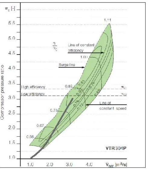
Figure. 4. 4 Compressor map VTR 304 ... 48
Figure. 4. 5 Turbocharged engine power (VTR 304) ... 49
Figure. 4. 6 Graphic operating line VTR 321 ... 50
Figure. 4. 7 Compressor map VTR 321 ... 51
Figure. 4. 8 Turbocharged Engine Power (VTR 321) ... 52
Figure. 4. 9 Graphic operating line ABB VTR 354 ... 53
Figure. 4. 10 Compressor map VTR 354 ... 54
xx
xxi
LIST OF TABLES
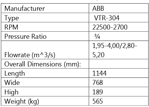
Table. 3. 1 ABB VTR 304 Specification ... 23
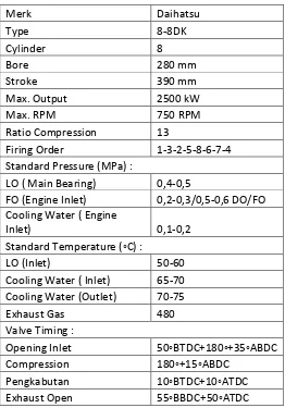
Table. 3. 2 Daihatsu 8-8dk specifications ... 24
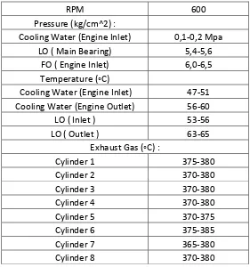
Table. 3. 3 Engine logbook of MV. Meratus Palembang ... 25
Table 4. 1 PropellerParticular ... 30
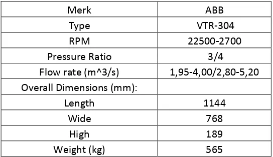
Table 4. 2 ABB 304 Turbocharger specifications ... 30
Table 4. 3 ABB 354 Turbocharger Specifications ... 31
Table 4. 4 ABB 321 Turbochaarger specificatons ... 31
Table 4. 5 KQ, KT, J in various speed design ... 35
Table 4. 6 Parameter of engine-propeller Characteristic ... 36
Table 4. 7 Turbocharger VTR 304 efficiency on dynamic ship speed conditions. ... 47
Table 4. 8 Turbocharged Engine Power (VTR 304) ... 49
Table 4. 9 Turbocharger VTR 321 efficiency on dynamic ship speed conditions ... .50
Table 4. 10 Turbocharged engine power (VTR 321) ... 52
Table 4. 11 Turbocharger VTR 354 efficiency on dynamic ship speed conditions ... 53
Table 4. 12 Turbocharged engine power (VTR 354) ... 55
Table 4. 13 Pressure ratio vs volumetric flow rate (VTR 304) ... 57
Table 4. 14 Pressure ratio vs volumetric flow rate (VTR 321) ... 58
xxii
1 CHAPTER I
INTRODUCTION
1.1 Background
Shipping is a cheap and reliable transport mode which provides significant contribution to national economics. As an archipelagic state, every island in Indonesia has its own main commodity for trading and therefore it needs effective and efficient transport mode to achieve competitive economy compared to other countries.
Container ships are important parts of a national supply chain management which needs efficient and effective goods transportation. Therefore, a continuous study on container ships capability is needed. Such technical assessment includes aspects of design, economy and performance of container ships. A more detailed study with the objective of achieving the best performance of container ships can focus only on one of those aspects.
In relation to ship performance, there are many possible topics which are prospective to be studied such as to measure performance of main engine of a ship which is an important strategy to optimize a ship performance as main mode of ocean transportation. One of the important aspects is the efficiency of fuel consumption as it relates to reduction of operational cost and air emission. Therefore, this issue has gained a strong enthusiasm of the ship owners to improve the efficiency of fuel consumption of ships.
Ravaglioli in 2015 argues that “Due to the increasing request for pollutant emissions and fuel consumption reduction, the optimization of turbocharger control has become a critical issue in modern engine management systems. Prior research demonstrates that pollutant emissions reduction and higher engine efficiency can be achieved through a proper combination of turbocharging technique and engine downsizing”. Therefore, following Ravaglioli (2015), a study on improvement of engine performance is urgently needed. According to him, a more reduction of emission and better engine
efficiency can be strengthened through a suitable mix between “turbocharging technique and engine downsizing”. So that the use of a certain type of
The working mechanism of turbocharger is basically to utilize efficiency of exhaust gas of engine, the kinetics and thermal energies of exhaust gas of engine are used to rotate the turbine of turbocharger. The construction of turbocharger consists of turbines and compressor which connect through shaft connector, it makes the compressor also rotates. In further development, research of turbocharger is focused on improving the resulted power optimization, so that the constant volume of combustion chamber could produce higher power. According to Kech (2014, p..): “a turbocharger compresses the air so that more oxygen flows into the combustion chamber. In this way, more fuel is burned and the power output of the engine increases
accordingly”.
Based on Kech in 2014, the function of turbocharging has to be suited with the engine power characteristics, however the challenge is that a turbocharger can be set up either for a wide speed range or a high boost pressure. The operating condition of the dynamic of main engine shows that the load engine works at different characteristic to produce power output. It can be concluded that a turbocharger needs an optimum of working area, exhaust gas in varied of load engine will produce different supply of pressure and supply of temperature to be processed by turbocharger.
Further research is needed for knowing the matched turbocharger that work at certain operating conditions of the dynamic main engine. The surge line and the efficiency are shown in the compressor map graphic, indicating turbocharger working area. Surging occurs at the maximum pressure point while the flow rate capacity reached at the minimum point. The efficiency of turbocharger can be determined also from the compressor map.
Therefore, there is an urgent need of a project research to determine which turbocharger is the most suitable based on the load engine conditions and power output of the main engine that can be increased by turbocharger. The research on MV. Meratus Palembang examines the existing turbocharger characteristic and another type of turbocharger, to know how optimal every selected turbocharger compared to the operating conditions of dynamic main engine. The main goal of such research is to achieve an optimum of engine performance on MV. Meratus Palembang.
1.2 Problem Formulation and Scope
3
sufficiently support main engine at some point only. The existing turbocharger and the selected turbocharger are compared to know each characteristic to support main engine for achieving optimum combustion. Based on the description above the statement problems for this thesis are presented as follows:
1. How are the matched points of the turbocharger with engine in every type of turbocharger?
2. How is the influence of pressure ratio to the volumetric flow rate that supply the main engine?
1.3 Problem limitation
1. The project research is solved by calculation based on Grinevtsky Mazing Method in Marine Internal Combustion Engine Book written by N. Petrovsky.
2. The method is to determine the value of volumetric flow rate and the power output produced by turbocharged.
3. Performance of turbocharger is analysed based on exhaust gas constant value.
4. The mechanical efficiency of bearing friction of turbocharger is ignored. 5. Economical factor is ignored in due to the research is devoted to the
value of turbocharger efficiency.
1.4 Objectives
1. To obtain and to compare the efficiency of each type turbocharger against the main egine from the compressor map graphic.
2. To obtain the air mass density value against the variation of turbocharger pressure.
1.5 Benefits
5 CHAPTER II
LITERATURE STUDY
Compressed engine cycle or well known as diesel engine is device that generates power, the basic concept using a high compression to adding a pressure in combustion chamber. With high compression, air fuel mixture burnt automatically without igniter. Internal combustion engine generate power from combustion process, air and fuel mixture in chamber are compressed until its ignite than forcing the piston to rotating. The process happens repeatedly to generate energy to make a mechanical movement of working fly wheel. Diesel is one of internal combustion engine example, found by Dr. Rudolf Diesel, the high efficiency of diesel engine is usually use in large vehicles and industrial systems where the improvements in cycle efficiency make it advantageous over the more compact and lighter weight spark ignition engine. Introducing turbocharger as a tool to help internal combustion engine to achieved higher efficiency, the tool is a simple centrifugal compressor for supplying more pressured air to make the compression ratio in combustion chamber increase. As many researches approve the turbocharged engine have a high efficiency.
2.1 State of The Art
The idea of supplying air under pressure to a diesel engine was voiced by Dr. Rudolf Diesel, found an engine with a higher efficiency than a usual engine, it was campaigned at early 1896. Turbocharger itself was introduced by a Swiss
engineer, Alfred Buchi, who patented his research “pulse system” in 1925.
The pulse system is feeds from exhaust gases of the engine through narrow pipes to the turbocharger turbine, thus driving the compressor. The pressure variation in the small volume pipes allows overlapping of the inlet and exhaust, permitting scavenging of the compression space of the engine cylinders with
clean air. Cylinders that do not disturb each other’s scavenging process can be
connected to one pipe (turbine gas inlet) in accordance with the firing order of the engine. The pressure Pcyl in the cylinder, Pexh. In the exhaust pipe, Pr in the air
receiver and the scavenging period (where the inlet and exhaust are simultaneously open is not disturbed by the exhaust pulses of other cylinders. This pulse system was the foundation for the future success of turbocharging.
Figure.2. 2Engine test data from the lecture given by Alfred Buchi in 1928 (Turbo Magazine,1992-1996)
In December 1928, Alfred Buchi gave a lecture at the Royal Institute of Engineers at The Hague in the Netherlands. The lecture was told about thermal load of a diesel engine does not essentially increase when turbocharged. An improvement in fuel consumption due to the better mechanical efficiency could also be shown. And it was seen from a comparison of four turbocharged 10 cylinder single acting 4 stroke engines and four turbocharged 6 cylinder double
7
was given very early on turbocharging the engine driven scavenging pumps of the 2 stroke engine. However, since the turbocharger efficiency necessary for this was not available, it took many more years for this goal to be reached. (Turbo Magazine, 1992-1996)
The performance of turbochargers can be defined by the pressure ratio, mass flow rate and efficiency characteristics of the compressor and turbine, plus the mechanical efficiency of the bearing unit. (Diesel Engine Reference Book, 2011)
One of the first studies of this phenomenon is stated by Rautenberg’s et al. in 1983. These authors emphasis the heat transfer influence on the turbine power and on the compressor outlet temperature. The increase of this temperature
leads to a density decrease, which isn’t favorable to the engine volumetric
efficiency. The usual isentropic efficiency is wrongly used. It doesn’t define the aero dynamical quality of the compression, because it considers the heat transfers between the turbine, the compressor and the surrounding area. Thanks to experimental tests, the authors note a strong dependence between turbine inlet temperature and compressor outlet temperature. The geometrical turbocharger characteristics, mainly the distance between compressor and turbine, appear to influence greatly the heat fluxes.
Concluding from the research of Kech et al at 2014, the performance of an internal combustion engine can be increased by adding turbocharging. A turbocharger compresses the air so that more oxygen flows into the combustion chamber and a vehicle engine is driven dynamically it has to deliver high performance from idling speed right through to maximum revs and the turbocharger characteristics have to be matched to the broad power band. The challenge is that a turbocharger can be set up either for a wide speed range or a high boost pressure.
From above studies turbocharger characteristic is important to consider the revs of its engine, the dynamical operation of engine will show how the turbocharger character. Also pressure air supply and temperature air supply to the combustion chamber is very effecting to the efficiency of turbocharger that support internal combustion engine to achieved more power.
2.2 Principal Work of Turbocharger
The development of turbocharger focusing at the improvement of power output and its efficiency. Turbocharger is a device that support internal combustion engine to generate a higher power, because of its pressure is supplying to the combustion process so the compression ratio of main engine becomes denser. Basically turbocharger is a one form of a compressor and turbine that connected each other by a shaft bearing that designed as reduce-less as it can be. Turbocharging technology is a key factor to the future engine manufacturer. This technology is very common for using in the diesel engine, because diesel engine main concept is auto-ignition, with a high compression ratio in the combustion chamber.
Figure.2. 3 Turbocharger
(http://foro.clubjapo.com/t/los-turbos-guia/28297/2)
Turbochargers system furthermore has many complex structures, as time goes by the form of turbocharger is develop to many type and system. Every turbo-manufacturer has their own structure as a response of the demand on industrial and automotive needs.
9
compressor part work to suck an ambient air around the main engine, and the ambient air is going to the intercooler part, at the intercooler part the ambient air is cooled to achieve denser of air particle. The cooler ambient air temperature the density of air become higher, which mean the air ratio become more compressed, this is in line with the concept of diesel engine that higher compression ratio of a marine internal combustion can produced more efficiency to the combustion process.
Figure.2. 4 Turbocharger Principle Work
(http://www.mech4study.com/2016/02/difference-between-supercharger-vs-turbocharger.html)
As the structure is connected to each other the turbine power must have a same power in compressor. The power required to rotate the compressor by turbine, is defined as:
( ) [2.1]
m is the mass density of air (kg/m3), u is the specific heat of air (J/kg-K), va is
the speed of air flow mass, and tan σ is the angle of air flow (Hamid Keshaverzi: 2005). From the formula above shows that turbine power is correlated with the speed of air flow mass and the compressor power depends in the amount of pressure and air temperature.
working area of turbocharger (can be seen at turbocharger compressor map) is much related to the engine revolutions as already describe at many references.
2.3 Exhaust Gas Method
Exhaust gas from internal combustion engine generally has two type forms:
1. Constant Pressure
This type of exhaust gas is supported by main manifold that connected from each of exhaust gas outlet in every cylinder and directly connected to turbine inlet port. This system enabling every exhaust gas supply same concentration to inlet port of turbine, causes fluctuate air supply to a turbine. The pressure in manifold becomes lower and constant.
Figure.2. 5 Constant air pressure (Turbo Magazine,1992-1996)
The constant pressure system has the same large exhaust gas receiver irrespective of how many cylinders the engine has. The same applies to single exhaust systems, where the exhaust receiver volume is reduced in comparison with constant pressure systems. (Turbo Magazine, 1992-1996)
11
The Figure of 2.6 shown Pexh and Pr effecting the turbocharger efficiency,
due to the piston movement from BDC-TDC-BDC the constant air pressure always have a same value point.
2. In pulse type turbocharger, the exhaust gas directly enters the turbine side and drives the turbine with the exhaust gas energy. The connection from the exhaust side of an engine is directly connected to the turbine side of a turbo charger.
Figure.2. 7 Pulse air pressure (Turbo Magazine,1992-1996)
The pipe connections from the exhaust gas towards the turbine side are generally small in length and exhaust grouping is provided to prevent the blowback of gases from one cylinder to another.
Pulse system allows the size of the exhaust pipe that is relatively smaller, 1 to 3 of cylinder space accommodated by exhaust pipes which directly connected to the turbine, so that what makes the pulse system type has a smaller size of exhaust gas pipe.
process. When the first cylinder in open condition, the exhaust gas pressure in the exhaust pipe will increase, and when the pressure value is greater than the air pressure into the engine can result in improved of turbine performance. (Turbo Magazine, 1992-1996)
Figure.2. 8 Turbocharger efficiency for pulse pressure effect (Turbo Magazine,1992-1996)
From the above figure pulse air pressure can support turbocharger with both characteristic, during the piston movement from BDC-TDC-BDC air pressure can supply from each manifold because every manifold its own direct supply to inlet port of turbine.
2.4 Compressor
The main parts of the turbocharger compressor are the compressor wheel (inducer and impeller), diffusor, air inlet and air outlet casing. This part is the part to forcing an air supply to the combustion chamber. The characteristic of a compressor is shown in the compressor map graphic; from the compressor we can get the value of turbocharger efficiency, surge line, and operating line.
13
Figure.2. 9 Surging cycle (Turbo Magazine,1992-1996)
The figure shows the line of constant speed and the operating line of the engine. The intersection of the two lines is working point A if a slight increase in air volume occurs, more pressure is required on the operating line and the pressure becomes lower on the constant speed line. The volume has to decrease again to the point of equlibrium A if, at the same charger speed, a slight reduction in airflow occurs, the pressure will increase although less pressure is required on the working line. Eqilibrium is then once more at point A. The working point A is stable on the part of constant speed line inclined downwards with increasing volume. If a slight decrease in volume occurs at point B (at the same pressure as A), then the pressure on the constant speed line decreases. The compressor cannot maintain the required pressure, the volume continues to decrease and the compressor surge. Point B is not stable on that part of the constat speed line that is inclined upwards (with increasing volume). (Turbo Magazine, 1992-1996)
maintenance procedure must be considered with proper, to avoid the failure for maintenance assets.
Figure.2. 10 Compressor map (Turbo Magazine,1992-1996)
The figure shown that from compressor map we can know the characteristic of compressor. Dashed line shown the compressor is working at surge point, when the operating line intersect with that line, it means compressor working at high pressure ratio but low of volumetric air flow, work of the compressor is on sufficiently condition. Line of constant speed that can be seen at the graphic, when the engine revolution is at the constant value point, every volumetric air flow and pressure ratio is at the fluctuate value point. And the efficiency of turbocharger also can be seen at the graphic, the value point of turbocharger efficiency is the intersection between the compressor island and the operating line of engine-turbo condition.
15
and volumetric air flow in each of engine revolutions. It can be assured that the revolutions of engine are affecting the value of operating line design point.
2.5 Turbine
The turbocharger turbine, which consists of a turbine wheel and a turbine housing, converts the engine exhaust gas into mechanical energy to drive the compressor. The gas, which is restricted by the turbine's flow cross-sectional area, results in a pressure and temperature drop between the inlet and outlet. This pressure drop is converted by the turbine into kinetic energy to drive the turbine wheel.
In the developement as a main part of turbocharger components, turbine are generally divided at two type of form. Radial turbine type, use for internal combustion at power output 500 kW – 4900 kW. The second once is the axial turbine type, axial turbines are used on medium-slow speed engines. They are perfectly capable of accepting the exhaust gas from engines running on heavy fuel oil. The turbine retains its high effeciency over a very long period of time, the more so when reasonable maintenance is provided. The axial turbine is able to supply an adequate output with good efficiency to drive the compressor from low presure ratios upwards, thus assuring good part-load perfomance of the engine. The latter is specially important for fixed-pitch propeller drives. Turbochargers with axial turbines are found on ships, in diesel power stations and on diesel locomotives, dredger, and other vehicles large diesel engine.
The turbine's characteristic behavior is determined by the specific flow cross-section, the throat cross-cross-section, in the transition area of the inlet channel to the volute. By reducing this throat cross-section, more exhaust gas is dammed upstream of the turbine and the turbine performance increases as a result of the higher pressure ratio. A smaller flow cross-section therefore results in higher boost pressures.
The turbine's flow cross-sectional area can be easily varied by changing the turbine housing.
Besides the turbine housing flow cross-sectional area, the exit area at the wheel inlet also influences the turbine's mass flow capacity. The machining of a turbine wheel cast contour allows the cross-sectional area and, therefore, the boost pressure, to be adjusted. A contour enlargement results in a larger flow cross-sectional area of the turbine.
Turbines with variable turbine geometry change the flow cross-section between volute channel and wheel inlet. The exit area to the turbine wheel is changed by variable guide vanes or a variable sliding ring covering a part of the cross-section.
In practice, the operating characteristics of exhaust gas turbocharger turbines are described by maps showing the flow parameters plotted against the turbine pressure ratio. The turbine map shows the mass flow curves and the turbine efficiency for various speeds. To simplify the map, the mass flow curves, as well as the efficiency, can be shown by a mean curve.
For high overall turbocharger efficiency, the co-ordination of compressor and turbine wheel diameters is of vital importance. The position of the operating point on the compressor map determines the turbocharger speed. The turbine wheel diameter has to be such that the turbine efficiency is maximized in this operating range.
2.6 Grinevetsky Mazing Method
17
1. Charging Process (Petrovsky, 1976)
Calculation for temperature of air at the turbocharger outlet (Tsup), based on The Marine Internal Combustion Book page. 28;
( )
, °K [2.2]
Where :
: Ambient temperature, temperature of the outside air in °K.
: Pressure of air at the turbocharger outlet. : Absolute pressure, 1 atm.
: exponent of the polythropic compression lene of the turbocharger, 1,7-2 for centrifugal blower.
Calculation for temperature of air through the intercooler (Tisup),
based on the Marine Internal Combustion Book page. 203;
, °K [2.3]
Where :
: Temperature of air at the turbocharger outlet.
: 60 °C based on engine logbook of MV. Meratus Palembang.
Calculation of air temperature in the end process of charging (Ta), based on the Marine Internal Combustion Book page. 29;
( ) [2.4] Where :
: Temperature of air through the intercooler.
: With a value at 10-15 °C for Turbocharged Diesel Engine : Scavenging characteristic value, 0,03-0,04 for four-stroke diesel engine.
: Rate temperature on diesel engine, 700-800 °C
Calculation of air pressure in the end process of charging (Pa),
based on the Marine Internal Combustion Book page. 27;
2. Compression Process (Petrovsky, 1976)
Calculation for compression temperature (Tc), Based on the
Marine Internal Combustion Book page. 32;
, °K [2.6]
Where :
: Air temperature in the end process of charging. : Compression Ratio.
: Polytropic exponent with value, 1,34-1,39
Calculation for Pressure in the end of compression process (Pc),
based on the Marine Internal Combustion Book page. 32;
[2.7]
Where :
: Air pressure in the end process of charging. : Compression Ratio.
1 : Polytropic exponent with value, 1,34-1,39
3. Combustion Process (Petrovsky, 1976)
Calculation for increasing of pressure point (, Based on the Marine Internal Combustion Book page. 44-45;
[2.8]
Where :
Pz : Pressure at the end of combustion combustion process
Pc : Pressure at the end of compression process
Calculation for actual air value (Lt), based on the Marine Internal Combustion Book page. 38;
[2.9]
Where :
19
The total quantity of moist combustion gases, based on the Marine Internal Combustion Book page. 39;
, moles [2.10] Where :
: 44.0095 g/mol and 1 gram( ) = 0,0227 moles. : 18.01528 g/mol and 1 gram( ) = 0,0555 moles. : 28.0134 g/mol and 1 gram( ) = 0,0357 moles. : 31.9988 g/mol and 1 gram( ) = 0,0313 moles.
Coefficient of molar change (,based on the Marine Internal
Combustion Book page. 40;
[2.11]
Where :
: Actual air value
: The total quantity of moist combustion gases.
Coefficient of molar change for residual gas (,based on the Marine Internal Combustion page. 40;
[2.12]
Where :
: Coefficient of molar change.
: Scavenging characteristic value, 0,03-0,04 for four-stroke diesel engine.
Calculation for increasing of pressure point (, Based on the Marine Internal Combustion Book page. 44-45;
Calculation for combustion temperature (Tz), based on the
Marine Internal Combustion Book page. 45; °C [2.14]
Where :
: Calculation for increasing of pressure point. : Coefficient of molar change for residual. : Calculation for compression temperature.
Calculation for prelimanary expansion ratio (), based on the Marine Internal Combustion Book page. 50;
[2.15]
Where :
: Coefficient of molar change for residual gas. : Increasing pressure point.
: Compression temperature. : Combustion temperature.
4. Expansion process (Petrovsky, 1976)
Calculation for the degree of subsequent expansion (), based on the Marine Internal Combustion Book page. 52;
[2.16]
Where :
: Compression Ratio.
: Prelimanary expansion ratio.
2.7 Parameter of Power Calculation
21
*( ) ( ) ( ) +, kg/cm2 [2.17]
Where :
: Pressure at the end of compression process. : Compression Ratio.
: Coefficient of molar change for residual gas. : Increasing pressure point.
: The degree of subsequent expansion.
n1 : Polytropic exponent with value, 1,34-1,39
n2 : Polytropic exponent for expansion, the value is between 1,15-1,3.
To obtain the proper value of the mean indicated pressure the value of (Pit) should be corrected for the rounding off of the sharp angles in the basic indicator diagram which will make its form approach that of the actual indicator diagram. The corrected mean indicated pressure of a four-stroke or two-stroke engines has the following form:
, kg/cm2 [2.18]
Where :
: The theoritical of mean indicated pressure value.
: Is the correction factor of a diagram for four-stroke engine (0,95-0,97). Mean effective pressure occurs during the mechanical efficiency of shaft and main engine. Mean effective pressure (Pe) is a value when Pit and Pi already been
calculated. We can obtain the mean effective pressure from:
, kg/cm2 [2.19]
Where :
: The corrected mean indicated pressure.
: Mechanical efficiency for turbocharged four-stroke engine (0,8-0,88).
, HP [2.20]
Where :
: Mean effective pressure, : Volume displacement, m3
23 CHAPTER III
RESEARCH METHODOLOGY
The research methodology is the main framework of conducting research. The methodology covers all process of research for addressing the research problem, containing data collection, data processing, and results of analysis. The research methodology is presented in the form of a flow chart which composes of research steps from the beginning to the completion of the research. The flow charts are to show the research steps as well as to convince the readers that the research is academically accountable, therefore from the methodology, the research quality could be judged.
3.1 Literature Study
Literature study is the initial process to provide theoretical foundation of the concerned research. Through reviewing references which vary from books, published papers, websites and other sources, the research is sufficiently supported by conceptual foundation based on previous studies of the relevant field to the research topic. In addition through a literature study, the research gap which leads to further new research can be identified.
3.2 Data Collection
In this step, the required data for analysis is collected which consists of engine
logbook, engine’s specifications, turbocharger specifications of every selected type to be used for the projection of operating line within the compressor map.
Manufacturer ABB
Type VTR-304
RPM 22500-2700
Pressure Ratio ¾
Flowrate (m^3/s)
1,95-4,00/2,80-5,20
Overall Dimensions (mm):
Length 1144
Wide 768
High 189
Weight (kg) 565
The table of 3.1 is an example of a turbocharger specification, making operating lines of turbo-engine characteristic is critical important to consider the data from turbocharger specification, we can calculate the operating line from thermodynamics process of engine. The other turbochargers specification can be seen at the attachment.
Table. 3. 2 Daihatsu 8-8dk specifications
Merk Daihatsu
Type 8-8DK
Cylinder 8
Bore 280 mm
Stroke 390 mm
Max. Output 2500 kW
Max. RPM 750 RPM
Ratio Compression 13
Firing Order 1-3-2-5-8-6-7-4 Standard Pressure (MPa) :
LO ( Main Bearing) 0,4-0,5
FO (Engine Inlet) 0,2-0,3/0,5-0,6 DO/FO Cooling Water ( Engine
Inlet) 0,1-0,2
Standard Temperature (◦C) :
LO (Inlet) 50-60
Cooling Water ( Inlet) 65-70 Cooling Water (Outlet) 70-75
Exhaust Gas 480
Valve Timing :
Opening Inlet 50◦BTDC+180◦+35◦ABDC
Compression 180◦+15◦ABDC
Pengkabutan 10◦BTDC+10◦ATDC
Exhaust Open 55◦BBDC+50◦ATDC
25
connected each other to the turbocharging technology. The more complete specification of main engine can be seen at the attachment.
Table. 3. 3 Engine logbook of MV. Meratus Palembang
RPM 600
Pressure (kg/cm^2) :
Cooling Water (Engine Inlet) 0,1-0,2 Mpa LO ( Main Bearing) 5,4-5,6
FO ( Engine Inlet) 6,0-6,5
Temperature (◦C)
Cooling Water (Engine Inlet) 47-51 Cooling Water (Engine Outlet) 56-60
LO ( Inlet ) 53-56
LO ( Outlet ) 63-65
Exhaust Gas (◦C) :
Cylinder 1 375-380
Cylinder 2 370-380
Cylinder 3 370-380
Cylinder 4 370-380
Cylinder 5 370-375
Cylinder 6 375-385
Cylinder 7 365-380
Cylinder 8 370-380
Engine logbook in table 3.3 is used as a comparison of main engine specification data and engine logbook data. The different value in some data, is to be selected where to be input in grivetsky mazing method to get a good basic design point. The more specific data can also be seen in the attachment.
3.3 Main Engine-Turbocharger Calculation
3.4 Determined Turbocharger Efficiency
To determine the efficiency of turbocharger is by reading the compressor map. The turbocharger characteristic is shown at the compressor map which crosscuts the trend line of the value of operating line. Within the compressor map characteristic, there is a part so called as a compressor island, so that the level of efficiency can be determined, by identifying the cutting point in every compressor island.
3.5 Turbocharged Main Engine Power Calculation
With the supply of lower air pressure and air temperature due to turbocharger function, the calculation is continued by determining the composition of combustion process, through calculating the mole amount of CO2, H2O, N2, and
O2. Those molecules are resulted from the combustion of engine which
influences the value of the power output.
3.6 Data Validation
The data resulted from the above calculation is not necessarily valid, therefore this step is called as validation process. If the resulted data is not valid, it would be recalculated. If the data is already valid then it can be continued to the next process.
3.7 Conclusion and Recommendation
This step is to draw the conclusion and the recommendation of this research. This final process is to comprehensively analyze the result, by exploring the better knowledge of the role of turbocharger to improve the engine performance, so that it can be used as a reference to further study the dynamic of engine operation impacted by varies of turbocharger characteristics.
3.8 Flow Chart
27
29 CHAPTER IV
Result and Discussion
4.1 Basic Data For Calculation Ship Particular
MV. Meratus Palembang is a Multi Purpose Ship equipped for carriage container-heavy cargo. Ship is operated by Meratus Line, the data of ship is collected from Meratus Line as a shipping company.
1. Name : MCP Altona
2. Type : Container&Heavy Cargo
3. LOA : 117 m
4. LWL : 112,23 5. Beam : 19,7 m 6. Height : 8,5 m
7. Draught : 6,562 m (tropical draught) 8. Class : BKI&GL
9. Built : 9 December 2006,
China-Shandong Huanghai Shipbuilding Co. Ltd
Engine Specifications
MV. Meratus Palembang is a Multi Purpose Ship equipped for carriage container-heavy cargo. Ship is operated by Meratus Line, the data of ship is collected from Meratus Line as a shipping company.
1. Manufacturer : Daihatsu
2. Type : 8-8dk
3. Total Cylinder : 8
4. Bore : 280 mm
5. Stroke : 390 mm
6. Max. output : 2500 kW 7. Max. RPM : 750 RPM 8. Max. Cylinder pressure : 155 Bar 9. Compression Ratio : 13,3
10.Firing Order : 1-4-7-6-8-5-2-3
Propeller Particular
data of propeller particular will showing the effect to engine load, due to maintaining the ship design speed.
Table 4. 1 PropellerParticular
Type B5-60 Db 3,3 m P/D 0,76
N
189,8 rpm Ae/A0 0,6
Z 5
Turbocharger Specifications
Turbocharger specifications contain the value of pressure ratio and volumetric flow rate, compressor map from manufacturer is a result from those two data.
Table 4. 2 ABB 304 Turbocharger specifications
Merk ABB
Type VTR-304
RPM 22500-2700
Pressure Ratio 3/4
Flow rate (m^3/s) 1,95-4,00/2,80-5,20 Overall Dimensions (mm):
Length 1144
Wide 768
High 189
31
Table 4. 3 ABB 354 Turbocharger Specifications
Merk ABB
Type VTR-354
RPM 189000-228000
Pressure Ratio 3/4
Flowrate (m^3/s) 3,00-6,30/4,20-7,80 Overall Dimensions (mm):
Length 1627
Wide 1159
High 1134
Weight (kg) 1680
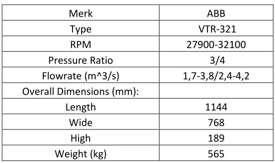
Table 4. 4 ABB 321 Turbochaarger specificatons
Merk ABB
Type VTR-321
RPM 27900-32100
Pressure Ratio 3/4
Flowrate (m^3/s) 1,7-3,8/2,4-4,2 Overall Dimensions (mm):
Length 1144
Wide 768
High 189
Weight (kg) 565
4.2 EPM Calculation
Lewis, Edward V., Principles of Naval Architecture, Volume II Resistance, Propulsion, and Vibration, the Society of Naval Architects and Marine Engineers, NJ, 1988. Holtrop Method;
1. Total Resistance
Calculation for total resistance ( ), reference from Principal Naval Architecture page. 93;
2. Reynolds Number
Calculation for reynolds number (Rn), based on reynold number
formulation;
[3.2]
Where :
: is the maximum velocity of the object relative to the fluid (m/s). L : is a characteristic linear dimension, travelled length of the fluid; hydraulic diameter when dealing with river systems (m).
: 0,9242x10⁻⁶ for temperature 15°C.
3. Calculation Frictional Coefficient (CF)
For the holtrop method, CF that is used is from ITTC 1957, reference
from Principal Naval Architecture page. 59 with the following formula:
C
F=
( ) [3.3]
4. Ship Correlation Allowance (CA)
Calculation for Ship Correlation Allowance (CA) for (T/LWL 0,04), the
formula stated on Principal Naval Architecture page. 93;
( ) [3.4]
Where : T/LWL = 0,0585
5. Viscous Resistance Coefficient(CV)
Calculation for Viscous Resistance Coefficient(CV), reference from
Principal Naval Architecture page. 162;
( ) [3.5]
Where :
( ) : from the ship particular data with further consideration of calculation the value is 5,075.
: Frictional coefficient.
33
6. Wake Fraction Coefficient (w)
Calculation for Wake Fraction Coefficient (w), reference from Principal Naval Architecture page. 163;
√ [3.6]
Where :
: Coefficient Block of Ships : Viscous resistance coefficient : Diameter of propeller
: Length of ship i the midship position : Draft of ship in the maximum load
7. Froude Number (Fn)
Calculation for reynolds number (Rn), based on reynold number
formulation;
√
[3.7]
Where :
: is the maximum velocity of the object relative to the fluid (m/s). L : is a characteristic linear dimension, travelled length of the fluid; hydraulic diameter when dealing with river systems (m).
: 9,81 m/s2 for the mean value of gravity on earth.
8. M1 and M2
Calculation for M1 and M2 coefficient, reference from Principal Naval
Architecture page. 92;
m1 = 0,01404(L/T)-1,7525(1/3/L)-4,7932(B/L)-C5 [3.8]
m2 = C6 X 0,4 e-0,034 X (Fn^-3,29) [3.9]
Where :
: for CP<0,8 the value is 1,172042.
9. Rw/W
The calculation for Rw/W is formulated in
from Principal Naval Architecture page. 92-93;( )
[3.10]
Where :
: The value is 1
: The value is -0,9 for Fn 0,4
λ : coefficient related to L/B ratio, for L/B<12, so λ as following is (1,446Cp– 0,03 L/B)
10. Displacement Weight (W)
The calculation for Rw/W is formulated in
Principal Naval Architecture page. 65;[3.11]
Where :
: The value for sea water is 1,025 kg/m3.
: 9,81 m/s2 for the mean value of gravity on earth. : Displacemet of ship.
11. Coefficient of Resistance (CT)
The calculation for Coefficient of Resistance (CT) is formulated in
Reference Principal Naval Architecture page. 65;
[3.12]
Where :
: Wetted hull surface.
: The value for sea water is 1,025 kg/ m3. : Velocity of ship.
12. Deadrise at mid-chne length ()
35
( ) ( ) [3.13]
Where :
: Coefficient of Resistance. : Trhust-deduction fraction. : Wake fraction.
: Diameter of ship.
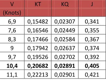
V KT KQ J
(Knots)
6,9 0,15482 0,02307 0,341 7,6 0,16546 0,02449 0,355 8,3 0,17466 0,02584 0,367 9 0,17942 0,02637 0,374 9,7 0,19526 0,02702 0,392
10,4 0,20682 0,02891 0,405
11,1 0,22213 0,02901 0,421
From this parameter we can find the value of KT, KQ, J. The value of KT will affecting the Resistance of ship in every speed. KQ value will obtaining the power output that need by ship to moved from its resistance. J is the value of advance coefficients that determining the value of propeller revolutions. Every value can be difined from the open water graphic.
As table 4.5 shown that the data KQ, KT, J is calculated based on the holtrop method. Every value depend on its (Vs), the slower the speed the KQ is linear according the data. Its prove, at the slow speed engine running the power output of engine that need to thrust the speed resistance become less than the higher speed. This characteristic summarized on the open water diagram. Every type of propeller and ratio of pitch/diameter have their own characteristic, so in every type of propeller the open water diagram is differences.
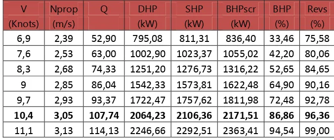
Table 4. 6 Parameter of engine-propeller Characteristic
V Nprop Q DHP SHP BHPscr BHP Revs
(Knots) (m/s) (kW) (kW) (kW) (%) (%)
6,9 2,39 52,90 795,08 811,31 836,40 33,46 75,58 7,6 2,53 63,00 1002,90 1023,37 1055,02 42,20 80,06 8,3 2,68 74,33 1251,20 1276,73 1316,22 52,65 84,65 9 2,85 86,04 1542,33 1573,81 1622,48 64,90 90,16 9,7 2,93 93,37 1722,47 1757,62 1811,98 72,48 92,78
10,4 3,05 107,74 2064,23 2106,36 2171,51 86,86 96,36
11,1 3,13 114,13 2246,66 2292,51 2363,41 94,54 99,00
Table 4.6 showing every parameter to make an engine-propeller characteristic. The value KQ from the open water diagram B5-76 propeller type in ship design speed (Vs=10,4 knots) is 0,02891. From that value we can calculate the Torque power (Q = KQ x
x n2 x D5), the Delivered Horse Power (DHP = 2 x
x Q x n), the power in main shaft (SHP = DHP/s), and the value of Brake Horse Power (BHP = SHP/G). The percent of BHP and revolutions indicated the engine working at some range of power output load and the speed flywheel also at some range in percent units.Figure. 4. 1 Graphic of engine-propeller characteristic 20 30 40 50 60 70 80 90 100
60 80 100 120
Engine Propeller Characteristic
Engine Propeller Characteristic
37
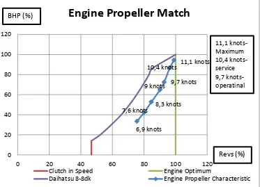
Figure. 4. 2 Graphic of engine-propeller match
Figure 4.2 is the graphic of engine propeller match, envelope line showing Working Load of Daihatsu 8-8dk Operational Characteristic and Revolutions of Daihatsu 8-8dk. The line of engine-propeller is plotted to the envelope line to sowing the trend line of engine propeller match. If the line of engine-propeller is throughout the envelope line it is indicated that the propeller is not necesarry applicable to the engine load operational characteristic.
The calculation of engine-propeller characteristic must be done to know the load of main engine in various design speed. This one is critically consider to know the effect to the turbocharger in various speed (dynamic main engine operating conditions). So further study about selection of turbochargers on dynamic main engine conditions can be continue.
4.3 Grinevetsky Mazing Method Calculation Example :
1. Charging Process
Calculation for temperature of air at the turbocharger outlet (Tsup), based on The Marine Internal Combustion Book page. 28;
6,9 knots 7,6 knots 8,3 knots
9 knots 9,7 knots 10,4 knots 11,1 knots
0 20 40 60 80 100 120
0 20 40 60 80 100 120
Engine Propeller Match
Clutch in Speed Engine Optimum
( )
, °K [3.14]
( )
Where :
: Ambient temperature, temperature of the outside air in °K.
: Pressure of air at the turbocharger outlet. : Absolute pressure, 1 atm.
: exponent of the polythropic compression turbocharger, 1,7-2 for centrifugal blower.
Calculation for temperature of air through the intercooler (Tisup),
based on the Marine Internal Combustion Book page. 203;
, °K [3.15]
, °K
Where :
: Temperature of air at the turbocharger outlet.
: 60 °C based on engine logbook of MV. Meratus Palembang.
Calculation of air temperature in the end process of charging (Ta), based on the Marine Internal Combustion Book page. 29;
( ) [3.16]
( ) , °K
Where :
: Temperature of air through the intercooler.
: With a value at 10-15 °C for Turbocharged Diesel Engine : Scavenging characteristic value, 0,03-0,04 for four-stroke diesel engine.
39
Calculation of air pressure in the end process of charging (Pa),
based on the Marine Internal Combustion Book page. 27;
( ) , atm [3.17]
Calculation for Engine Displacement (Vd), based on the Marine Internal Combustion Book page. 26;
[3.18]
Where :
R : (m) L : Length of Stroke (m)
Calculation for actual combustion chamber value (L), based on the Marine Internal Combustion Book page. 38;
[3.19]
Where :
: Diesel factor coefficient (1,7-2)
: the value can be replaced by engine displacement for calculating the actual air value in chamber room.
Calculation for Volumetric efficiency (
), based Basic Diesel Engine Theory : Peter Theory, the equation stated;[3.20]
Where :
: Actual combustion chamber value. : Engine Displacement.
Calculation for air density (
), based on ideal gas law of Dalton the equition is stated;[3.20]
Where :
: Pressure in the end process of charging (pa) : Avagadro Number, 287,1 (J/kg)
: Temperature in the end process of charging.
Calculation for mass flow rate of air in the combustion room (ṁ), based on the Diesel Engine Reference Book: 1984, the equation is stated;
( ) [3.21]
( )
Where :
: Rotational speed engine (rps). : Engine Displacement ( )
: Density of air (kg/ ) : Volumetric Efficiency.
Calculation for Volumetric air flow (V), based on the Diesel Engine Reference Book: 1984, it can be calculated by;
41
̇ √
Where :
: Mass flow rate of air : Ambient Temperature (K) : Boost Pressure (kg/ )
Calculation for Volumetric air flow ( ), it is stated on the compressor map specifications for corrected Volumetric air flow;
̇ ̇ (√ ) [3.23]
̇ (√ )
Where :
: Volumetric flow rate.
: Temperature Inlet or ambient temperature (K).
2. Compression Process
Calculation for compression temperature (Tc), Based on the
Marine Internal Combustion Book page. 32;
, °K [3.24]
, °K
Where :
: Air temperature in the end process of charging. : Compression Ratio.
: Polytropic exponent with value, 1,34-1,39
Calculation for Pressure in the end of compression process (Pc),
, kg/cm2
[3.25] , kg/cm2
Where :
: Air pressure in the end process of charging. : Compression Ratio.
1 : Polytropic exponent with value, 1,34-1,39
3. Combustion Process
Calculation for air quantity in combustion chamber at moles unit (n), based on ideal gas law stated;
[3.26]
, moles
Where :
: Air pressure in the end process of charging (pa). : Volume of combustion chamber Lt (m3)
: Avogadro number 287,1 (J/kg K)
: Air temperature in the end process of charging.
The total quantity of moist combustion gases, based on the Marine Internal Combustion Book page. 39;
, moles [3.27]
0,214 moles
Where :
43
Coefficient of molar change (,based on the Marine Internal
Combustion Book page. 40;
[3.28]
Where :
: Actual air value.
: The total quantity of moist combustion gases.
Coefficient of molar change for residual gas (,based on the Marine Internal Combustion page. 40;
[3.29]
Where :
: Coefficient of molar change.
: Scavenging characteristic value, 0,03-0,04 for four-stroke diesel engine.
Calculation for increasing of pressure point (, Based on the Marine Internal Combustion Book page. 44-45;
[3.30]
Where :
Pz : Pressure at the end of combustion process / maximum cylinder pressure (167,48 kg/cm2)
Calculation for increasing of pressure point (Tz, Based on the Marine Internal Combustion Book page. 45;
[3.31]
( )
Where :
: Calculation for increasing of pressure point. : Coefficient of molar change for residual. : Calculation for compression temperature.
Calculation for prelimanary expansion ratio (), based on the Marine Internal Combustion Book page. 50;
4. Expansion Process
Calculation for the degree of subsequent expansion (), based on the Marine Internal Combustion Book page. 52;
[3.32]
4.4 Example of Power calculation :
45
*( ) (
)
(
)
+
, kg/cm
2
[3.33]
*( ) ( ) +
,
kg/cm2
Where :
: Pressure at the end of compression process. : Compression Ratio.
: Coefficient of molar change for residual gas. : Increasing pressure point.
: The degree of subsequent expansion.
n1 : Polytropic exponent with value, 1,34-1,39
n2 : Polytropic exponent for expansion, the value is between
1,15-1,3.
To obtain the proper value of the mean indicated pressure the value of (Pit) should be corrected for the rounding off of the sharp angles in the basic indicator diagram which will make its form approach that of the actual indicator diagram. The corrected mean indicated pressure of a four-stroke or two-stroke engines has the following form:
, kg/cm
2[3.34]
, kg/cm
2Where :
: The theoritical of mean indicated pressure value.
: Is the correction factor of a diagram for four-stroke engine (0,95-0,97).
Mean effective pressure occurs during the mechanical efficiency of shaft and main engine. Mean effective pressure (Pe) is a value when
Pit and Pi already been calculated. We can obtain the mean effective
pressure from:
, kg/cm
2Where :
: The corrected mean indicated pressure.
: Mechanical efficiency for turbocharged four-stroke engine (0,8-0,88).
Brake horse power is the value of actual engine power which giving
an energy to the engine’s drive shaft. The value can also be found
by measuring with a dynamo meter and break the power. BHP in marine sector is a value that marine diesel engine can be produced, the BHP performance of marine diesel engines have a different characteristic for each type from many engine-manufacturer.
, HP
[3.36]=
2935,378
, HPWhere :
: Mean effective pressure, : Volume displacement, m3
: Speed of crankshaft, rpm : Number number of cylinders
47
4.5 Turbocharger VTR 304 :
Figure. 4. 3 Graphic operating line ABB VTR 304
Figure 4.3 is the operating line of turbocharger due to the effect on dynamic main engine operating conditions. The ship design speed is affecting the pressure supply in combustion chamber, the volumetric flow rate variance is depends on the pressure supply of air to the combustion chamber.
Table 4. 7 Turbocharger VTR 304 efficiency on dynamic ship speed conditions
No V Load Psup/Po 300 (knots) (%) kg/cm2 m3/s (%)
1 6,9 33,46 0,37 0,87 -
2 7,6 42,20 0,66 1,05 -
3 8,3 52,65 0,93 1,26 -
4 9 64,90 1,56 1,63 65
5 9,7 72,48 1,89 2,18 76
6 10,4 86,86 2,63 2,84 78
7 11,1 94,54 3,00 3,15 80 0,00 0,50 1,00 1,50 2,00 2,50 3,00 3,50
0,00 1,00 2,00 3,00 4,00
Operating Line
propeller-ABB VTR 304 Psup
Figure. 4. 4 Compressor map VTR 304
49
Table 4. 8 Turbocharged Engine Power (VTR 304)
No Psup Nb
kg/cm2 (kW) 1 0,39 62,79034 2 0,85 202,6948 3 1,13 360,3463 4 1,41 713,1853 5 1,98 1313,762 6 2,83 2627,525 7 3,11 3220,595
Figure. 4. 5 Turbocharged eng