93 A cable modem system is actually a portion of the entire system that a
cable operator must deploy in order to start supplying Internet access ser-vices to subscribers. The cable modem system—that is, the CMTS and all the cable modems—provide only the last-mile(also sometimes called the
first-mile)access over the cable operator’s network. The rest of the sys-tem lies in the cable operator’s and service provider’s network, behind the headend.
The remaining elements of entire system are composed of the cable operator’s backend network, the service provider’s backend network, a variety of servers, and the connection to the rest of the Internet. Some cable operator’s provide their own Internet service; others work with an Internet service provider (ISP) partner. The partner’s network may or may not be co-located in the cable operator’s backend network. The servers in the network provide traditional Internet services, such as email and Web access; but there are also specialized servers for cable modem manage-ment and, perhaps, for streaming media services.
A new subscriber is added to the cable modem network via a customer service system that provisions elements of the entire network to accept the new cable modem and to allocate resources to the subscriber. Two of
Internet Services over Cable
C H A P T E R
these resources are Internet addresses and bandwidth allocation. To the new subscriber, the path to obtaining service may be rocky and problem-atic; however, the system has been designed to accommodate future cus-tomer installations and auto configuration. Parts of these refinements are in operation in today’s systems.
Once installed, the subscriber is provided with an always onservice. This offers the advantage of rapid response time from power-up on the home computer, as it avoids the delays with dial-up modems. In addition, cable modem services frees up the phone line that was previously used for Internet access.
Managing the cable modem Internet access system requires the ISP and the cable operator to proactively plan deployments and upgrades to sup-port the growing number of subscribers and their subsequent bandwidth needs.
The environment and technology for cable networks continues to improve. Many multiple systems operators (MSOs) have taken advantage of digital optical networking technology to improve the interconnections of headends and to create a better backend distribution network for video, voice, and data.
Service Provider System
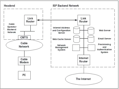
Figure 4.1 shows the basic architecture of the Internet services network for a cable operator and ISP. This example shows that the ISP and the cable operator run distinct networks.
Several network elements make up the entire system, from the cable operator’s headend through the ISP to the Internet:
■■ One or more CMTS systems
■■ Cable operator backend network
■■ Headend link router
■■ ISP link router
■■ ISP backend network
■■ Internet address and configuration server
■■ Web server
■■ Email server
■■ ISP Internet router, plus provisioning and authentication system
■■ Network management system
The actual number and placement of these elements will vary from deployment to deployment, based on the needs of the cable operator and the ISP; thus, the entries in the preceding list should be considered a set of generic building blocks for the system.
It is possible to operate more than one CMTS at a headend. The number of CMTSs deployed is based on the cable topology within the operator’s network, as well as the number of subscribers who are being supported. Obviously, the more subscribers, the more data capacity is needed.
The Internet uses routing to get IP packets from place to place. A link router is required within the cable operator’s headend. This router con-nects the headend facility with the ISP’s facility. In many cases, the CMTS will itself serve as a router, which means the connection to the ISP may be provided directly by the CMTS. However, if more than one CMTS is
Cable
installed at the headend, there will be a local cable operator backend net-work, which interconnects each CMTS with the router. Typically, this is a 100Mbps Ethernet network.
At the ISP, a link router is used to support that side of the interconnec-tion between the ISP’s and the cable operator’s facility. The actual physical device used may be a port from a multiple-port router. The ISP link router connects to the ISP’s backend network.
Within the ISP’s network, several servers are required to support the cable subscribers. First is an Internet address and configuration server. It uses the Dynamic Host Configuration Protocol (DHCP) as well as the Triv-ial File Transfer Protocol (TFTP) to assign IP addresses and provide con-figuration information to cable modems, as well as to provide IP addresses to subscribers’ personal computers. DHCP and TFTP are two widely used standardized protocols for the autoconfiguration of Internet devices.
ISPs provide a customer Web environment to support their cable users. The servers are typically located in the ISP’s facilities. Email servers follow the same deployment as Web servers and are also located at the ISP.
A Web cache server provides a mechanism by which Web pages are tem-porarily stored locally. A subscriber’s Web browser is directed to use the cache server as a proxyserver. This is important because any frequently accessed but unchanging Web pages are provided locally by the cache server rather than by the original server. Caching Web pages is a technique employed by browser applications to reduce the need to pull Web pages over the Internet connection. In this model, the additional ISP’s network Web cache server also helps to reduce load on the connection to the Inter-net, an important advantage, because, today, the major subscriber activity is surfing the World Wide Web. A Web cache server can be located at the ISP or at the headend.
The ISP Internet router connects the ISP with the rest of the Internet. The ISP typically runs more than one of these routers to connect to differ-ent ISP peers. This builds in some redundancy as a safeguard in case of link failure.
The provisioning and authentication system is used to manage the other elements to provide services to subscribers. For example, when new sub-scribers set up their service with the cable operator’s customer service department, the provisioning system may perform a number of operations, including:
■■ Configure the Internet address server to recognize the new cable
modem.
■■ Configure the Internet address server to provide one or more IP
■■ Assign a bandwidth allocation configuration to the server, which is
used by both the CMTS and the cable modem to regulate data capac-ity allocation for the subscriber.
■■ Configure a new email address on the email server.
■■ Configure a custom Web page on the Web server.
■■ Test the connection to the subscribers’ new cable modem (if
con-nected and turned on).
Provisioning and authentication is a fairly detailed task, and is very dependent on the ISP and the cable operator. In some cases, the provi-sioning system may be linked back to a cable operator data management system, which keeps billing information along with other subscriber information. The details of an individual cable operator’s system are beyond the scope of this chapter, but the general procedures just listed are illustrative of those that must be taken to bring a new subscriber online.
The management system is responsible for monitoring the health of each network element, from the ISP Internet link router down to each and every cable modem. If any problems arise, the management system can identify where and what the problem is, and alert network opera-tions personnel. In addition, the management system may be able to issue trouble ticketsas a means of tracking fixes. Moreover, every active cable modem on the network is itself a remote sensor; this enables the cable operator to determine the health of the cable network’s plant. By observing statistics that are kept in each cable modem and CMTS, the operator can spot certain problems before subscribers experience any service degradation.
P R O A C T I V E N E T W O R K M A N A G E M E N T For the cable operator, every
cable modem is a remote sensor that can be used to identify problems in the cable network before they become problems for subscribers.
Subscriber Provisioning
A cable operator can’t provide high-speed data service to a customer unless the following three pieces are in place:
may only be able to provide two-way services to a portion of the plant. Subscribers not in the activated portion will have to wait until the operator enables more plant.
■■ There must be an active drop line to the subscriber’s home.
■■ The subscriber must have a personal computer that can support both
the hardware and software applications for the service.
The goal of cable modem efforts in North America is to allow a sub-scriber to purchase a cable modem off the shelf or via the Web, self-install the modem at home, request service, and start operation almost immedi-ately. Unfortunately, the cable networks and provisioning systems cur-rently cannot yet meet that goal, although they are continuing to advance. At this time, most provisioning is performed manually.
Manual Provisioning
Manually provisioning a new subscriber follows these basic steps:
1. The subscriber calls up the cable operator or cable ISP and requests new service. In some cases, the subscriber can initiate this by filling out a form on the cable ISP’s Web site.
2. The subscriber talks to a customer service representative (CSR) over the phone. The CSR collects and verifies the following infor-mation:
a. Account information. The subscriber may already have cable TV service; if not, he or she is considered a new subscriber.
b. That cable service can be provided to the subscriber’s home. This step validates that the downstream and upstream channels used by a CMTS are already present, or can be accessed easily, on the cable that is passing the new subscriber’s home address.
c. That the subscriber’s personal computer has the necessary hard-ware and softhard-ware features to support the connection to the ser-vice. The personal computer can be a generic PC running
d. That new subscriber can receive service, and his or her personal computer is capable of supporting the service.If so, the CSR schedules an appointment for the subscriber with a cable techni-cian for the installation. (In some cases, a subscriber may not know the capability or configuration of his or her personal com-puter, in which case a technician is sent out, essentially hoping for the best.) Billing information is confirmed at this time. The CSR may also set up a login name and password or email account name and password at this time.
3. The CSR uses the provisioning system to update the necessary servers with the information for the new subscriber. This includes any login or email names and passwords, IP address assignments, and bandwidth allocation parameters.
4. The technician arrives at the subscriber’s home and verifies the qual-ity of the drop cable. This is done by visually inspecting the drop cable for wear, age, and part number. The connectors at either end are inspected for corrosion and proper fit. (End connectors are easily replaced.) Finally, the ground block is inspected, and replaced if needed. Inside, some wiring changes may be needed to accommodate the connection of the new cable modem. For example, a new splitter may be installed and a new cable extended to, say, the den.
5. The technician installs the cable modem and verifies that it correctly operates by checking the status indicators. (The technician brings the cable modem, meaning the serial number and other information were already entered into the provisioning database.)
6. The technician prepares the customer’s personal computer. This may including installing the Ethernet NIC and any necessary software. Newer cable modems may provide a USB interface, in which case, the Ethernet NIC is not required.
7. Two modes of IP address assignment are possible for the personal computers. One is to manually enter the necessary information; the other is to configure the personal computer to use DHCP. After assigning the IP address, the PC is rebooted. The system will then have the following four pieces of IP network information configured: IP address assigned to the personal computer; IP subnetwork mask, also called the netmask value; IP address for the default gateway; IP address for one or more domain name servers (DNS).
Automatic Provisioning
An advantage of automatic provisioning is that it requires fewer visits by cable technicians to subscriber homes, and is, therefore, more economical for the cable operator.
Typically, today, a new cable modem subscriber will already have access to the Internet over a dial-up modem service and can surf to the cable ISP’s Web site to complete this process; otherwise, phone registration with a CSR will be necessary. Assuming the former, the process of automatically provisioning a new subscriber follows these basic steps:
1. The subscriber surfs to the cable ISP’s Web page and follows the pro-cedures for establishing new cable modem service. This includes fill-ing out forms with the information necessary to meet the three basic requirements (cable access, drop line, and capable personal com-puter) so that the Web registration system can proceed. In addition, and if known, the subscriber selects the bandwidth allocation level he or she wants.
2. If the Web registration process goes smoothly, the customer is given the option to purchase an approved cable modem from a local store or have one shipped to him or her. Billing information is also con-firmed in this step. The customer reads and accepts the service agreement.
3. The subscriber follows the directions to self-install the cable modem, then verifies correct operation.
4. The subscriber installs an Ethernet NIC, if required, and configures it for DHCP operation, then connects it to the cable modem’s Ethernet port.
5. The customer reboots the PC, launches a browser application, and starts to surf.
6. The cable ISP, recognizing that this is a newly attached cable modem and personal computer, intercepts the Web page access and directs it to a validation page. Here, the subscriber is required to enter infor-mation that validates the new service subscription. The Web page may require the subscriber to download cable ISP application soft-ware and reboot the computer again.
7. The subscriber now has full high-speed access to cable ISP services, as well as access to the Internet.
IP Protocol Stack Configuration on
the Subscriber’s Computer
The majority of subscribers who use cable modem service do not need, nor want, to know the details of the configuration of their PC; they just want to be assured that it is configured properly and that it works. Two methods are widely used to perform the actual initial IP network configu-ration of the computer:
■■ The cable technician configures the network settings.
■■ The subscriber is given the necessary information, and he or she
per-forms the configuration process.
Likewise, there are two methods by which a computer’s IP network can be configured: manually and automatically. Manual operation requires that the following four pieces of IP network information be entered by hand, by the person performing the configuration: the station’s assigned IP address, the IP subnetwork mask, the IP address of the default gate-way, and one or more DNS server IP addresses. Automatic means that computer must already be configured to accept these four pieces of IP network information using DHCP.
Here is a brief overview of how DHCP works on local area networks (LANs):
1. When a computer reboots, it reaches a point where it needs to initial-ize the IP network interface (if one is installed in the computer).
2. If the configuration information for the interface is set to access addresses automatically using DHCP, the IP stack initialization rou-tine transmits a broadcast packet, called a DHCP_Request packet, on the Ethernet interface. Inside the DHCP_Request packet is the 48-bit IEEE MAC address of the Ethernet interface. As a broadcast packet, the Ethernet packet is received by all Ethernet stations on the LAN, including one or more stations that are performing the role of a DHCP server. All nonserver stations just drop the packet.
a first-come first-served basis. When receiving a DHCP_Request packet, the server examines the static configuration first, then the pooled information. Whether static or pooled, the server constructs a DHCP_Reply packet that is transmitted back to the request station’s unique 48-bit MAC address on the Ethernet. The reply contains the four pieces of IP network information: the station’s assigned IP address, the IP subnetwork mask, the IP address of the default gate-way, and one or more DNS server IP addresses. (DHCP has addi-tional information that may be included in the reply, which is used for other functions. More on this in Chapter 5.)
4. The station receives the DHCP_Reply packet, extracts the IP infor-mation, and configures the IP protocol stack (as if the information were manually entered), and continues bringing up the computer.
DHCP has two other features that make it a very robust service: address lease timeand DHCP relaying. When DHCP assigns addresses in the DHCP_Reply packet, it also specifies the length of time for which the addresses are valid, called the lease time. According to the DHCP proto-col, it is the responsibility of the DHCP client (the home computer) to refresh its lease within that time; this is done automatically, and requires no subscriber knowledge and/or intervention. If this doesn’t happen, the server can reallocate the address to another computer. Sometimes, the cable operator or ISP will need to renumber its IP subnetwork, that is, change from one IP address block to another. This may be necessary when reconfiguring CMTS or cable plant topologies for alterations or to grow the network. The use of the lease enables each computer to periodically be reset (often, when next turned on) to new addresses.
The DHCP relay function enables a large network, composed of many LANs, to use a single DHCP server. In this mode, the router that connects the LAN to the rest of the network is configured with a DHCP helper address. Once configured, if the router receives a DHCP_Request packet, it modifies one field in the DHCP_Request packet and forwards it on behalf of the requesting station to a specific server. The server notes the information in the packet and sends the reply back to the router; the router then forwards the DHCP_Reply to the request station. This relay operation is performed transparently to the requesting station.
offers the advantage of allocating the same IP address to the computer yet maintaining address assignment flexibility when the computer is config-ured to use DHCP.
Manual IP Network Information Configuration
Most personal computers used by subscribers are one of three types: a PC running Microsoft Windows, an Apple Macintosh, or a PC running Linux. Each must be configured differently for cable, as explained here:
Windows 98.To configure the TCP/IP network information for an Eth-ernet interface, the subscriber must open the Network control panel located under Start Menu -> Settings -> Control Panel. The Network Control Panel displays various interfaces, from which the subscriber must open Properties for TCP/IP configuration for the Ethernet inter-face that is installed on the computer. Under Properties are various tabs that allow the user to manually enter the IP network configura-tion; alternatively a DHCP button is provided. Windows 98 (and 95) computers must be rebooted after the network information has been changed. This is the only way for any new configuration to take effect.
Windows 2000.The subscriber must open the Network and Dial-up Connections panel located under Start Menu -> Settings. From there, double click on the Local Area Connection item and select Properties. From there, double click on the Internet Protocol component. Select the “Obtain an IP address automatically” and “Obtain DNS server address automatically” buttons if the cable operator uses DHCP. Oth-erwise, select the “Use the following IP address” button as well as the “Use the following DNS server addresses” button and manually enter the address information that was provided by the cable operator.
MAC OS 9.Every new Apple Macintosh computer shipped today is cable modem-ready. Every Mac has a built-in Ethernet interface. figuration is straightforward. The subscriber opens the TCP/IP Con-trol Panel. The interface is set to Ethernet. The user chooses between manual configuration or DHCP. For manual, all the information is on the same page. After closing the panel and saving the configuration, the new settings take effect immediately; no reboot is necessary.
is available to the root user. Consult the administration manual that came with the specific Linux distribution release for more information.
Sizing the System
It is very important for the cable operator and cable ISP to proactively scale their services and interconnects so that subscribers never experience degradation in service below acceptable levels. What is “acceptable” is, of course, subjective, but broadly used relates directly to the subscriber’s view of the quality of the cable modem experience. Occasionally, news reports tell of conflicts that emerge because of the difference between the sub-scriber’s view of performance versus that of the cable operator. Most such conflicts can be explained easily. To that end, this section overviews how the cable operator and ISP scale the bandwidth capacity of their networks.
Transmission Control Protocol
Characteristics
Understanding the operational characteristics of the Transmission Control Protocol (TCP) is fundamental to sizing the cable modem system. TCP is a reliable transport protocol and, as such, has the capability to recover from packet loss errors that occur during retransmissions. Though the precise operation of the protocol is complex, a much simplified description of the operation between a sender and receiver will suit our purposes here:
1. The sender transmits a TCP data packet to the receiver. The packet contains a sequence number, which is a byte counter that indicates where in a stream of bytes the beginning of the packet is.
2. The receiver accepts data packets, and notes the sequence number.
3. The receiver sends an acknowledgment packet (ACK) to the sender, which specifies the number of bytes received correctly at this point. If there is a packet “hole,” that is, a lost packet between two good ones, the receiver acknowledges packets only up to the hole; neither the hole nor packets beyond are noted.
4. The sender receives the ACK, and knowing what it has sent, exam-ines what the receiver has gotten, then decides if one or more pack-ets need to be retransmitted. The sender also uses time delays, and will resend a packet if an ACK from the receiver gets lost.
Note that a receiver can be a sender, and vice versa. In the case of a sub-scriber surfing the Web from his or her personal computer, most of the packets from Web servers to the subscriber’s Web browser are TCP data packets, while packets from the Web browser back to the server are mostly TCP ACK packets. The size of the ACK packets is always less than the size of the data packets. This means that, from the sender to the receiver, the TCP packet flow is always asymmetric; that is, more bytes per second flow downstream to the subscriber in the form of data packets than flow upstream in the form of ACK packets.
In a normally operating system with no congestion or packet loss, the ratio of the downstream data rate for a World Wide Web TCP connection is approximately 8 to 10 times that of the upstream ACK rate. This means that, for proper sizing in the cable plant, the downstream data channel capacity should be sized at least better than 8 to 10 times the upstream channel capacity.
The flow control nature of TCP has one observable attribute with respect to arrival of ACK packets at the sender. If the rate of ACK packets slows down, the rate of data packets also slows down. In a cable modem system with a predominance of Web-surfing traffic, the downstream TCP data rate is approximately 8 to 10 times the upstream TCP ACK data rate, while information is being transferred from the Web server to the sub-scriber’s computer.
T C P A S Y M M E T R Y In a cable modem system where most traffic is from Web
surfing, the downstream TCP data rate is approximately 8 to 10 times the upstream TCP ACK data rate.
Today, much of the traffic on a cable modem system is from the TCP protocol. Other future services and applications will use TCP or other transport protocols. Web-browsing TCP traffic is asymmetric, as are streaming video and audio. In contrast, interactive voice and video is much more symmetric—that is, the data rate flow in each direction (i.e., in the downstream and the upstream) will be approximately the same for the ser-vice. But because these symmetric services will be mixed with normal TCP Web-browsing traffic, traffic as a whole will be less asymmetric than pure TCP Web browsing.
user wants to download a file, the service contacts the app on the com-puter of the person providing the file to transfer the file. If this type of public file-sharing service becomes more widely deployed and used, it will shift the balance between downstream and upstream traffic in a cable modem system, because more traffic will be leaving the sub-scriber’s home than arriving. Therefore, in consideration of this service and emerging services, understanding how to predict, then balance, between asymmetric and symmetric data loads on the cable system is essential.
S Y S T E M S I Z I N G Understanding the aggregate packet load, in terms of
sym-metry, on the cable modem system is important for future sizing of the system.
Sizing a cable modem system is directly tied to understanding the effi-ciencies of high-speed data channels, with respect to allocated RF band-width, as well as the capital dollars spent per homes passed.
Symmetric versus Asymmetric Cable
Modem Systems
Recall from Chapter 2 that, initially, cable modem systems were symmetric in nature—they had one downstream data channel and one upstream data channel. These channels were identical in their data-carrying capacity size, and usually provided about 10Mbps of service.
These early systems were operated as LANs; they are distinguished from the modern cable modem system by their use of a “dumb” transverter architecture. This meant that the Internet connection to the cable ISP was located off one of the cable modems in the system. Consequently, traffic from a Web server sender also used the upstream channel to reach a cable modem receiver. This had the effect of blending the traffic load, as just described, so that it was more symmetrical.
The major deficit of these systems was that a 10Mbps downstream channel could not operate at peak efficiency versus a modern 30Mbps downstream channel. Thus, the system could not support as many
modems as the modern system; and that 20Mbps of potential downstream data-carrying capacity was wasted. Therefore, these early systems were limited by the symmetrical—one down, one up channel—nature of the system.
band-width, only downstream bandwidth. Nevertheless, in this architecture, downstream and upstream capacity and RF bandwidth are wasted for these reasons:
■■ Downstream capacity of 10Mbps or 3Mbps is much less than modern
system capacity of 30Mbps. This means that the cable operator loses access to, potentially 20 to 27Mbps for every symmetric channel deployed.
■■ Based on the asymmetric nature of TCP, the maximum upstream data
rate will be approximately 8 to 10 times less than the downstream data rate. This means that approximately 8Mbps of the upstream channel would remain unused by TCP traffic. This suggests that approximately 75 percent of the upstream RF bandwidth is wasted.
M O D E R N S Y M M E T R I C S Y S T E M S A R E I N E F F I C I E N T Modern,
so-called intelligent, headend systems that use one downstream channel and one upstream channel of the same data-carrying capacity waste both downstream and upstream RF bandwidth due to the characteristics of TCP traffic flow.
Modern asymmetric systems, such as those based on the specifications developed for North America, are more efficient than their symmetric pre-decessors. The reason can be traced to early recognition during standards development that using the highest data rate downstream channel as pos-sible and supporting multiple upstream channels comprise the best approach for efficient RF bandwidth allocation and growth capability to meet subscriber needs. Today, as noted earlier, in the absence of interac-tive voice and video services, the predominant traffic comes from World Wide Web browsing. This means that until the traffic ratios change, a CMTS only needs an upstream channel that is approximately one-eighth to one-tenth the data-carrying size of the downstream channel. And because modern systems support multiple upstream channels, channels can be added to suit changing the traffic mix or until the downstream channel becomes fully loaded.
The ability to tailor upstream bandwidth to suit the subscriber base means that the cable operator can efficiently allocate RF bandwidth as needed in the plant, on a per-CMTS basis. This scaling model best matches capital dollars to a given subscriber population.
Adding Another CMTS and Node
Splitting
In service, a CMTS cable modem system is much like an Ethernet switch in a business office. If the capacity of the switch is too heavily loaded, users get degraded performance. One remedy is to buy another switch, intercon-nect it with a high-speed link, and distribute the load. The same is true with cable modem systems. Eventually, the RF data channels will become loaded to the point at which performance degrades. At this time, the cable operator has at least two choices:
■■ To allocate additional downstream and upstream RF channels, and
install another CMTS.
■■ If not enough RF spectrum is available, to split the fiber node(s),
leave the old CMTS connected to the old nodes, and connect the new CMTS to the new nodes.
Both of these methods effectively double the amount of data-carrying capacity in the downstream and upstream. Choosing which method to use will be based on the cable operator’s business plan and budget. The power of node splitting is far-reaching, and can evolve over time, following traffic demands placed on the system; for example, a cable operator may only split the nodes where the data traffic requirements are high, and leave the others alone until capacity is reached. This incremental method allows cable operators to spend capital to follow revenues received from the tar-geted area of the cable plant.
It is important to note, however, that node splitting may affect sub-scriber IP address assignments. When a node is split to upgrade capacity, a new CMTS may be placed on the new fiber node, depending on the plans of the cable operator. If this new placement requires that the old IP subnet-work be renumbered or resubnetted, or if a new IP subnet is installed, then certain current subscribers will be directly affected. If they are using DHCP, these subscribers may need to reboot their computers and cable modems to obtain the new addresses to continue operation. Personal com-puters that have been manually configured will need to be manually recon-figured (as discussed previously in this chapter), then rebooted. The cable operator should send advance notice of this event, followed by directions to the affected subscribers.
M I N I - F I B E R N O D E S When node splitting leaves an HHP of a 50 to 100
Ultimately, node splitting can continue until the HHP for the node is fewer than 100 homes. This is called a mini-fiber node. Technologically speaking, it is possible to construct lower-cost CMTS systems and move the CMTS into the network to be located at the mini-fiber node.
Clearly, a cable operator today has a great deal of scaling capacity in modern cable modem systems and HFC plants. However, other areas, aside from scaling cable network data-carrying capacity affect cable modem performance.
Cable Modem Performance: Separating Fact
from Fiction
Simply put, subscribers of high-speed broadband services are paying for shorter delays when accessing the Internet. If dial-up modems met that demand, subscribers probably would stick with those. But as we know, the World Wide Web is quickly evolving toward more capacity-hungry applica-tions and services, and dial-up modems world just can’t cut it. Users want quick access, and they are willing to pay for it.
Initially, subscribers were very pleased by the performance enabled by cable modems . But all too soon, from time to time, performance degraded beyond acceptable limits. Subscribers and cable ISPs pointed the finger of blame at cable modem technology. As usual, however, where to place the blame was less clear-cut in fact. As mentioned at the beginning of this chapter, the cable modem system is just one facet of the larger system that brings the Internet into the home. As such, there are many places in the system where things can go awry. Some of these places are discussed in this section.
Plant RF Noise
We explained earlier in the book that ingress noise in the upstream chan-nel has been an issue for cable operators. Though the advent of HFC upgrades and better plant management reduced ingress noise dramatically, the first cable modems were deployed over all-coaxial systems, which were symmetric systems that did not use forward error correction (FEC). Some of these systems are still in place today and they are significantly less robust in the presence of noise than are modern systems that employ FEC and better channel RF modulation and demodulation systems.
the future, RF noise problems affecting cable modem performance will continue to be less of a problem. That is not to say that ingress noise can-not creep into a system; it can, but now it can be quickly found and reme-died. Furthermore, management and monitoring equipment for modern cable modem systems make it possible to remotely monitor RF plant health by observing CMTS and cable modem statistics such as packet error rates, FEC performance, and excessive modem registrations. This last point means that if a cable modem senses that it is disconnected from the CMTS either through timeouts or packet error problems, it will reboot and reregister. If this is happening too often, it is a sign of a plant RF prob-lem. Likewise, degraded packet error performance can be correlated to regions of the cable plant, and this correlation will help operators to more quickly locate any problems.
Capacity Allocation
Recall from Chapter 3 that early deployed, so-called dumb, cable modem systems could not adequately control the allocation of upstream and downstream data capacity resources; nor could some of the first deployed modern systems. They delivered bandwidth in a best-effort manner, as does the Internet. In contrast, take an early subscriber and move him or her from a dial-up modem to a lightly loaded cable modem system, and he or she will be rewarded with high-speed Internet access.
Complicating the issue was that early service agreements didn’t really address delivered bandwidth rates. Not surprisingly, as the number of active simultaneous subscribers increased on these systems, the available shared bandwidth decreased and users experienced degraded service. Sev-eral remedies are available to cable operators for avoiding these problems:
1. Be clear with subscribers up front about what they will experience with service over time.
2. Deploy a cable modem system that has adequate capacity allocation controls built into it.
3. Allocate one or more tiers of bandwidth allocation, and charge sub-scribers appropriately. Tailor capacity to cap subsub-scribers’ use of upstream data capacity to agreed-to limits.
4. Scale the system to ensure acceptable performance for subscribers.
Oversubscription
Every shared network, network link, and server in consumer use (e.g., ISP, telephone, and email services) are always oversubscribed. Service
providers continue to take on more subscribers than their base capacity permits, because statistics indicate that, typically, all those subscribers will not use the network at the same time. Oversubscription in general is a good thing. However, too much can lead to performance problems that affect every subscriber. The trick is for the operator and ISP to balance oversub-scription with performance, especially when the system is growing.
If, on the other hand, the cable modem system itself is undersubscribed, and there are no RF or “cockpit” errors with the cable modem system, yet the subscribers are complaining of degraded performance, the problem is elsewhere in the network. Nevertheless, whenever users have problems with cable networks, they tend to blame the cable modem.
In fact, any one of the following noncable modem-related problems can cause degraded performance:
■■ The cable operator backend network is overloaded.
■■ The link between the operator and the ISP is undersized.
■■ The cable ISP’s backend network is overloaded.
■■ The cable ISP servers are overloaded.
■■ The cable ISP’s link to the Internet is undersized.
The most typical problem is that the backend network or the link to the Internet is undersized. Why? As often is the case, it’s cost-related. It costs money to increase capacity, and the subscriber population might be grow-ing faster than the operator’s or ISP’s planned upgrades. There may also be cockpit and operator errors at any point in the network.
N O T E It doesn’t matter whether it is a cable system or a DSL system. If the
operator’s or ISP’s server or backend network elements (links and routers) are too oversubscribed, all users will experience unacceptable delays to the Internet. However, they will always point at the broadband modem system as being the culprit when in fact the problem is located elsewhere.
SONET in the Backend Network
(SONET) technology, a multimedia interconnection technology. When deploying SONET in the backend network, cable operators can use the same fiber and switching system for all their needs, including analog video distribution, as well as for digital distribution, including video, telephony, and Internet. This means that, as operators update their own backend net-works to SONET, they are laying down a network technology that can sup-port many future telecommunications services.
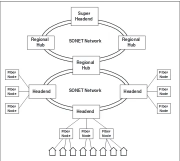
Developed by CableLabs in the early 1990s, SONET has three tiers: the bottom is the original headend, the next level is the regional hub, and top is the super-headend, as illustrated in Figure 4.2.
The first step in the evolution of this architecture was to interconnect headends to a regional hub with highly reliable, self-healing SONET tech-nology, then to move all nonlocal program origination from the headends to the regional hub. For example, this means moving the satellite dishes
Headend
which receive nonlocal programming, e.g., Home Box Office, from the headend to the regional hub.
The second step was to interconnect the regional hubs with a superhub, using highly reliable, self-healing SONET technology, then move all nonlo-cal program origination to the superhub.
Summary
This chapter presented an overview of providing Internet services to sub-scribers through a cable operator network. There are a number of chal-lenges that a cable operator and Internet service provider must overcome in order to provide consistent service to all new and old subscribers. These challenges include:
■■ Provisioning new subscribers with cable modem service. This may be
accomplished via manual or automatic means.
■■ Providing servers and services which meet the needs of the
sub-scribers. For example, electronic mail servers, Web servers, etc.
■■ Resizing the data carrying capacity of the system to meet the needs
of subscribers. For example, this includes installing higher capacity links to the Internet, installing additional CMTS facilities in a head-end, or fiber node splitting if the subscriber demand exceeds the capacity of the current data channel capacities.
■■ Locating and fixing RF plant noise problems promptly that interfere
with high-speed data communications.
In addition, many cable operators are following the CableLabs’ plan of converting backend networks to SONET technology. This permits the backend network to grow quickly in capacity as well as increase the relia-bility of the entire system.
For Further Information
There are two major nationwide cable ISPs: Excite@Home and Road Run-ner. More information about them and their services can be found at their Web sites:
Excite@Home: www.home.net