Experimental Study of DQPSK Modulation on SDR
Platform
1,2Eko Marpanaji, 2Bambang Riyanto T., 2Armein Z.R. Langi, 2Adit Kurniawan, 2Andri Mahendra, 2Thay Liung
1Departement of Electronics Engineering, Yogyakarta State University
Karangmalang, Yogyakarta 55281, Telp. +62-274-586168, Indonesia
2School of Electrical Engineering and Informatics, Institut Teknologi Bandung
Jl. Ganesa 10 Bandung 40132, Telp. +62-22-2501661, Fax. +62-22-2534133, Indonesia
Abstract. This Paper addresses Differential Quadriphase Shift Keying (DQPSK) modulation implemented on SDR platform for the development of digital data communications based on SDR. DQPSK modulation performance perceived at Packet Error Rate (PER) is evaluated in terms of Eb/No or S/N ratio, carrier frequency, bit rate, gain, roll-off factor of root Nyquist filter or root raised cosine filter, and of size of payload from delivered data. Based on this results, the smallest PER could be obtained by setting Eb/No value which is greater than 20 dB, carrier frequency of at least 0,3 MHz, optimum bit rate of 200 kbps, optimum range payload size of 2000 up to 4000 bytes, and roll-off factor of Nyquist or root-raised cosine filter of 0.4.
Keywords: Differential quadriphase shift keying, packet error rate, root raised cosine, software-defined radio, usrp.
1
Introduction
This paper describes the implementation of Differential Quadriphase Shift Keying (DQPSK) modulation scheme for communicating of digital data on
Software-Defined Radio (SDR) platform. This performance evaluation of DQPSK modulation scheme is also as a part of the current research in building SDR platform which can be reconfigured, including answering the research question of “How to design SDR platform using commodity components.”
Chen (2007) investigated a performance of Quadriphase Shift Keying (QPSK) modulation scheme to send a video digital data. All algorithms are modeled and simulated in Matlab, and the future works of that research is integrated those model into GNU Radio SDR platform using USRP[1]. Thus, the investigation of QPSK modulation scheme performance and its variants, including DQPSK, on SDR platform using Universal Software Radio Peripheral (USRP) is still needed.
Received ________, Revised _________, Accepted for publication __________
In this research, we investigated the performance of DQPSK modulation scheme implemented on SDR platform using USRP from GNU Radio. DQPSK modulation scheme is chosen in this research because the QPSK and DQPSK modulation is also widely used in recent wireless and cellular communication systems such as Satellite, CDMA, and cable modem.
The rest of this paper is organized as follows. Section 2 discusses about SDR architecture along with SDR’s characteristics. Section 3 presents the DQPSK modulation scheme. Section 4 presents system configuration used in this research. Section 5 presents DQPSK implementation and test result. Finally, Section 6 is conclusion.
2
Software-Defined Radio (SDR)
Software-defined radio (SDR), sometimes shortened to software radio (SR), was introduced for the first time in 1991 by Joseph Mitola[2]. The word of SDR was used to show a radio class that could be configured or re-programmed[3], thus resulted a kind application of wireless communication with mode and frequency band determined by software function. Ideally, SDR offers flexibility, re-configurability, scalability and as multi mode as possible.
SDR architecture is developed based on conventional radio functions. The difference is all functions of signal processing on conventional radio are carried out fully by hardware while the functions of signal processing on SDR are carried out as much as possible by software. The major key in building SDR is the placement of ADC and DAC components as a divider between analog and digital domain, thus the signal processing can be carried out using software.
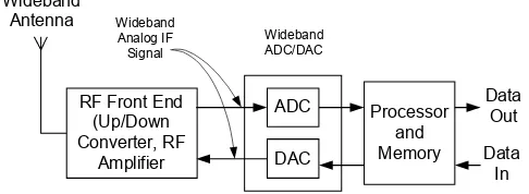
RF Front End
Figure 1Realistic SDR Architecture
communication, thus its change can be anticipated by upgrading the software[2][3]. However, the technology limitation and the expensive ADC/DAC wideband urge to change a little of SDR architecture in placing ADC/DAC. The more realistic SDR architecture places ADC/DAC wideband after Down Converter/Up Converter as shown in Fig. 1. With this architecture, the conversion from analog to digital or reverse is carried out on Intermediate Frequency (IF) signal which possesses lower frequency than RF signal. Today, that type of architecture are being developed widely and researched for the implementation. The SDR architecture for both transmitter and receiver can be presented with block diagram as shown in Fig. 2.
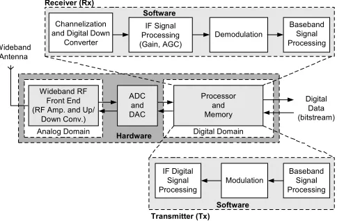
Software Transmitter (Tx)
Analog Domain Hardware Digital Domain
Software
Figure 2SDR Architecture for Transmitter and Receiver
The SDR platform performs transmitting and receiving functions. The transmitter (Tx) will perform some process such as base band signal processing, modulation, digital IF signal processing, and sending RF signal to the air. The receiver (Rx) will perform some process such as RF signal processing, channelization, digital IF signal processing, demodulation, and base band signal processing. As shown in Fig. 2, the computation process in the receiver will be more complex than the transmitter.
the computation complexity from processor. The formula to determine under sampling frequency is as shown below:
N
with 5 MHz bandwidth can be sampled with frequency of 22,5 MHz for m=1, or 17,5 MHz for m=2, or 11,66 MHz for m=3.
The next attention is on computation complexity which will determine the type and size of processor needed. The processor will generate the software of digital signal processing both for the receiver and transmitter. Besides to observe the functions generated by the software in determining computation complexity, the scalability factor for next development anticipation is also observed. All those steps will determine the processor’s size usually stated with Million Operations per Second (MOPS) or Million Instructions per Second (MIPS).
The biggest computation requirement is on the receiver side especially on filter part in channelization, which range from 100 to 200 operation/sample[3][5][6]. By using the sampling speed of 22.5 MHz will result 22.5 MSPS, thus it needs 2,250 until 4,500 MIPS. Other computation requirements are modulation and demodulation process. As a description, modulation and demodulation FM require more or less 100 to 150 MIPS[7]. The total of these computation requirements will determine the type and the number of processor used in SDR platform. It means, for bigger computation requirement and unable to be carried out by a processor, thus the SDR architecture can use parallel computation architecture by involving several processors or implementing a part of signal processing function in form of FPGA.
In the next section, the SDR implementation for digital data communication using Differential Quadriphase Shift Keying (DQPSK) modulation scheme along with the test result to observe its PER will be explained.
3
Differential Quadriphase Shift Keying (DQPSK) Modulation
effect in the communications channel which the signal passes through. This problem can be overcome by using the data to change rather than set the phase. The QPSK modulation scheme using differential encoding is usually called as
4
π -DQPSK or DQPSK.
The equation differential encoder to produce symbols is:
k k
k s b
s = −1⊕ (2)
where sk is current output symbol, sk−1 is previous output symbol, and bkis
current bit input. The ⊕ sign indicate modulo-2 operation. So sk only changes state (from binary '0' to binary '1' or from binary '1' to binary '0') if bk is a binary '1'. Otherwise it remains in its previous state. At the receiver, the received signal is demodulated to yield sk = ±1and then differential decoder reverses the encoding procedure (decoding process) and produces:
1
−
⊕ =
′ sk sk
b (3)
since binary subtraction is the same as binary addition. Therefore, bk′ = 1 if sk
and sk−1 differ and bk′ = 0 if they are the same. Hence, if both sk and sk−1 are
inverted, bkwill still be decoded correctly as bk′. Thus, the 180° phase ambiguity does not matter.
45o
Figure 3DPSK constellation diagram with identical Gray coding rotated by 45o
Table 1 summarizes a possible set of relationships between the phase transitions in the DQPSK modulation scheme and the incoming Gray code dibits[8].
Table 1Correspondence between input dibit and phase change for DQPSK modulation
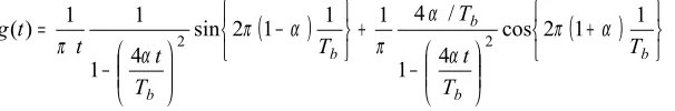
DQPSK used root Nyquist filter or root raised cosine filter as a pulse-shaping filter. This filter is used to reduces a number of spurious signals or to control the shape of digital data. The impulse response of root Nyquist filter is determined by equation [3]:
where
α
is roll-off factor of root raised cosine filter. This parameter controls the shape and bandwidth of the incoming signal.- 3 T b - 2 T b - T b 0 T b 2 T b 3 T b
- 0 . 4 - 0 . 2 0 0 . 2 0 . 4 0 . 6 0 . 8 1
t i m e
a
m
p
li
tu
d
e
N y q u i s t p u l s e s h a p i n g - t i m e a x i s
a l p h a = 0
a l p h a = 0 . 5 a l p h a = 1
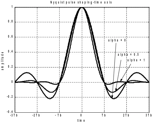
Figure 4Impulse response of a Nyquist filter in time domain with several chosen roll-off factors.
Fig. 4 shows the impulse response of a root Nyquist filter in time domain with several chosen of roll-off factor (alpha) values. One features of the Nyquist filter is that we always obtain impulse response is zero at nTb (n is integer: 1, 2, 3, ...) in the time domain. Therefore, when we set the synchronization point at
b
nT , one symbol never interferes with other symbols at this point.
The advantages of DQPSK are:
− the phase transitions from one symbol to the next are restricted to ±
π
4and ± 3
π
4so it will reduce the symbol ambiguity− using root raised cosine filtering, it has better spectral efficiency than
3.1
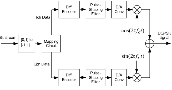
DQPSK Modulator
Fig. 5 shows the principle of a DQPSK modulator. The process occurred on modulator starts by changing bit stream with level 0 and 1 into bipolar stream bit with level -1 and 1. Next, bipolar stream bit is processed by mapping circuit to produce dibits for I-channel (Ich) and Q-channel (Qch), and then each dibit data will be processed by differential encoder using the rules of Table 1 separately. The output of differential encoder will be passed through a pulse-shaping filter to reduce its spurious signals. Finally, the output of pulse-pulse-shaping filter is converted to analog signal and modulated using RF signal cos(2
π
fCt)for Ich signal and sin(2
π
fCt)for Qch signal, where fC is carrier frequency.Both Ich and Qch signal are combine together to produce DQPSK signal.
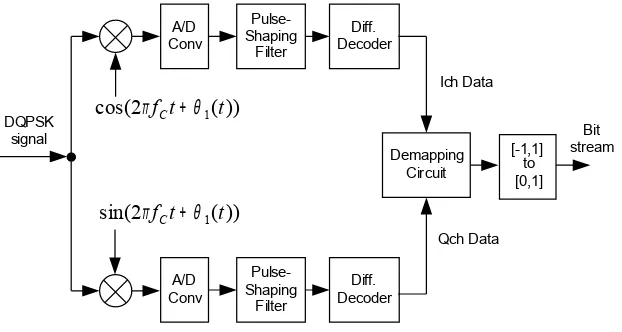
Demapping
Referred to the figure, originally demodulator of DQPSK will eliminate carrier frequency so that recover Ich and Qch signal. Both signal then converted in the form of digital signal through A/D Converter. Digital signal which yielded then passes through a pulse-shaping filter, and by using differential decoder dibit information transmitted by modulator will be recovered. Dibit information will be dissociated and become consecutive bit through demapping circuit, and bit stream with level - 1 and 1 will be returned to bit stream with level 0 and 1. Thus, consecutive information bit data transmitted by modulator of DQPSK can be found again at DQPSK demodulator.
4
System Configuration
Computer
Figure 7System configuration of SDR platform
Mainboard specification of USRP which used in this research is: (a) USB 2.0 port for connection to computer; (b) 12-bit ADC with speed of sampling 64 MSPS so that with principle of aliasing can conduct digitalization process with range frequency of aliasing - 32 MHz until 32 MHz; (c) 14-bit DAC with clock frequency 128 MSPS so have Nyquist frequency equal to 64 MHz; and (d) analog signal which yielded limited to 10 mWatt. While daughterboard using Basic Tx and Basic Rx so that there is no process of up/down converter and transmitter frequency limited 50 MHz maximum.
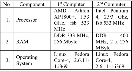
Specification of PC which used in this research is summarized at Table 2. Computer that used must have USB version 2.0 port to support connection with USRP board. Programming language used Phyton and a few block functions written in C++.
Table 2Computer spesifications that used in this research
System performance can be measured using one of the parameter which was often used in QoS, that is:
BER < 10-3, PLR or PER < 10-2, spread delay < 100 ms, and Gos > 95% [4].
In this research performance modulation scheme of DQPSK is measured in Packet Error Rate (PER) because data transmitted in the form of packet. Transmitting data as a packet will facilitate of SDR software integration with TCP/IP protocol for next development.
5
Implementation and Test Result
DQPSK modulator and demodulator described previously are implemented in SDR platform using PC and USRP board that commonly used in SDR experiment from GNURadio. The Board is a front side of SDR system and has functions to execute digitalization function (ADC-DAC) and filter channelization process. The digital signal processing used personal computer with USB port as a link between USRP and PC. Operating system used Linux with python programming language to develop the application. All software used for digital signal processing was open source from GNU Radio.
Figure 8Spectrum DQPSK signal
This experiment would observe the performance of digital communication
based on SDR system using USRP board with DQPSK modulation scheme.The
receiver because of limitation of Basic TX output power. The experiment was carried out to observe Packet Error Rate (PER) stated by the percentage of exactly accepted packet toward variation of Eb/No, bit rate, carrier frequency, roll-off factor, gain, and also payload size.
Fig. 8 shows the spectrum of DQPSK signal which has 15 MHz carrier frequency, bit rate 256 kbps, and roll-off factor 0.35. The result of observation is shown in Fig. 9 up to Fig. 14.
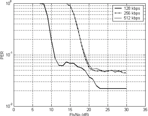
Figure 9The effect of Eb/No on PER
Fig. 9 shows the graph between variation of Eb/No concerning the PER value with 128 kbps, 256 kbps, and 512 kbps bitrate. Referred to the graph perceived, greater value of Eb/No hence smaller PER will be obtained. PER value will remain low for the value of Eb/No higher than 20 dB.
Variation of frequency carrier modulations of DQPSK will affect to PER value as depicted in Fig 10. The Graph obtained by arranged bit-rate transmitted data equal to 128 kbps, 256 kbps, and 500 kbps. In this experiment maximum frequency that tried is 44 MHz, and beyond that frequency cannot be handled by USRP using existing Basic TX. Referred to the graph, lowest PER value can be obtained if fC > 0.06MHz for 128 kbps, fC > 0.2MHz for 256 kbps, and
3 . 0
>
C
f MHz for 500 kbps. In another word, the minimum frequency which
Figure 10The effect of carrier frequency on PER
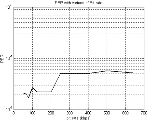
Figure 11The effect of bit rate on PER
greater than 200 kbps will increase the PER value and bit rate from 250 up to 600 kbps produced higher PER value.
Fig. 12 shows a graph of roll-off factor variation value at Nyquist filter to PER value. Referred to the graph, in general can be expressed that bigger roll-off factor value will result smaller PER, and optimum value for roll-off factor to get PER is 0.4. Roll-off factor value for the Nyquist of filter is 0 ≤ α ≤ 1, which value of roll-off equal to 1 referred as roll-off full-cosine which is very useful in signal timing extraction for the process of synchronization. Ever greater value of roll-off factor hence smaller influence of ISI.
Figure 12The effect of roll-off factor on PER
Figure 13The effect of gain PER
Fig 14 shows a graph concerning with variation of payload value to PER value. The graph indicated that the bigger transmitted payload value will produce the smaller PER. The maximum data size for this system is 4092 bytes, hence the optimum value for the measure of payload is 4092 bytes.
Referred to all the graphs of this research result, PER value which obtained with variation of Eb/No, carrier frequency, bit rate, roll-off factor, gain, and payload is very low that is closing 10-2. In spite of comparison with criteria measurement performance where PER < 10-2 not yet fulfilled. Hence, modulation scheme implementation of DQPSK at platform of SDR use USRP of GNU Radio still require to be completed either software and hardware so that we can get better performance of DQPSK modulation scheme on SDR platform using USRP GNU Radio.
6
Conclusion
Referred to this research result we can conclude that: In general can be said that modulation scheme of DQPSK which implemented at SDR platform using USRP from GNU Radio have better performance which is seen from PER value. Lowest PER Value can be obtained at Eb/No value > 20 dB, optimum bit-rate 200 kbps, carrier frequency bigger than 0,3 MHz, roll-off factor (alpha) is 0.4, optimum gain is 500, and optimum payload value is 4092 byte.
Continuation of this research is software development of SDR to improve the performance and also create application that adept to integration with communications protocol for example TCP/IP.
7
Acknowledgment
We would like to thank to the Dean of STEI ITB and the chief of PPTIK STEI ITB who have given opportunity also donation in order to accomplish this research. This paper is a part of the current research which has been conducting about SDR platform development, and it is using ITB Research fund year 2007 No : 0047/K01.03.2/PL2.1.5/I/2007. We also thank to all people who contribute to this research.
8
References
[1] Z. Chen., “Performance analysis of channel estimation and adaptive equalization in slow fading channel,” 2007, [On-line], Available at http://www.wu.ece.ufl.edu/projects/channelEstima-tion/full_files.zip.
[2] J. H. Reed, Software Radio: A Modern Approach to Radio Engineering.
New Jersey: Prentice Hall, 2002, pp. 2-3.
[3] J. Mitola III, Software Radio Architecture. Object-Oriented Approaches to Wireless Systems Engineering. Canada: John Eiley & Sons, Inc, 2000, pp. 1-34.
humanre-sources/external/training/special/ DISP2003/DISP-2003_L01A_20Feb 03.pdf (20 Feb 2003).
[5] A. K. Salkintzis, H. Nie, P. T. Mathiooulos. (1999, August). ADC and
DSP Challenges in the Development of Software Radio Base Stations.
IEEE Personal Communications.
[6] C. H. Dick. (2001). Design and Implementation of High-Performance FPGA Signal Processing Datapath for Software Define Radios. [Online].
Available: http:// www.eetasia.com/ARTICLES/2001AUG/
2001AUG09_ ICD_AMD_RFD_ TAC01 .PDF.
[7] J. Huie, P. D’Antonio, R. Pelt. (2005). Synthesizing FPGA Cores for Software-Defined Radio. [Online]. Available: http://www.altera.com/ cp/fpga-cores-for-sdr.pdf.
[8] S. Haykin, “Communication System,” 4th ed. New York: John Wiley & Sons, Inc, 2004, pp. 362-365.
[9] H. Harada, R. Prasad, Simulation and Software Radio for Mobile Communications. Boston: Artech House, 2002, pp. 75-76.