PHASE SHIFT KEYING (PSK) TRANSCEIVER DESIGN
STEVER AK ABONG
Universiti Malaysia Sarawak
2000
'Jl{7872
P39 5842 2000P. KHIDMAT MAKLUMAT
1IIIIill~l~
0000081693ll~~I~I~
illlllll
l
ll
PHASE SHIFT KEYING(PSK) TRANSCEIVER DESIGN
STEVER AK ABONG
Tesis Dikemukakan Kepada
Fakulti Kejuruteraan, Universiti Malaysia Sarawak Sebagai Memenuhi Sebahagian daripada Syarat
Penganugerahan Sarjana Muda Kejuruteraan
Dengan Kepujian (Kejuruteraan Elektronik dan Telekomunikasi) 2000
Borang Penyeraban Tesis Universiti Malaysia Sarawak
RI3a BORANG PENYERAHAN TESIS
Judul: Phase Shift Keying(PSK) Transceiver
SESIPENGAJIAN: 97/98 Saya STEVER ANAK ABONG
(HURUF BESAR)
mcngak'U mcmbenarkan tesis ini disimpan di Pusat Khidmat Maklumat Akademik, Universiti Malaysia Sarawak dengan syarat-syarat kegunaan seperti berikut:
I. Hakmilik kertas projek adalah di bawah nama penulis melainkan penulisan sebagai projek bersama dan dibiayai olch UNIMAS, hakmiliknya adalah kepunyaan UNlMAS.
2. Naskhah salinan di dalam bentuk kertas atau mikro hanya boleh dibuat dengan kebenaran bertUlis daripada penulis.
3. Pusat Khidmat Maklumat Akademik, UNIMAS dibenarkan membuat salinan untuk pengajian mereka. 4. Kertas projek hanya boleh diterbitkan dengan kebenaran penulis. Bayaran royalti adalah mcngikut kadar
yang dipersetujui kclak.
5. • Saya membenarkan/tidak !)lembenarkan Perpustakaan membuat salinan kertas projek ini scbagai bahan pertukaran di antara institusi pengajian tinggi.
6. ** Sila tandakan ( 3 )
c=J
SULIT (Mengandungi makiumat yang berdrujah kesclamatan atau kcpentingan Malaysia seperti yang termaktub di dalam AKTA RAHSIA RASMI1972).[::::=J
TERHAD (Mengandungi maklumat TERHAD yang tclah ditentukan oleh organisasil badan di mana penyelidikan dijalankan).~ TIDAK TERHAD
(T
(TAND~ENULIS)
YELIA)A1amat tetap: 191, Lorong Keranji 4FIA,
Tabuan Dcsa, 93350 Kuching, Sarawak. Dr.Lim Tiong Hieng (NAMA PENYELIA)
Tarikh: 27 Mac 2000 Tari.kh:
CATATAN Poloog yaog lidak berkeoaao.
Jika Kerlas Projek illi SULIT atau TERHAD, si\a lampirkao sural daripada pihBk berkuasal organisBsi berkenaan dengan menyerlakall sekaU lempob kerl85 projek. Ini perlu dikelaskan
UNIMAS/15/02/02 .
27 Mac 2000
Pengurus
Pusat Khidmat Maklumat Akademik Universiti Malaysia Sarawak
Puan,
Tesis pelajar - Stever Ak abong
Tesis pelajar ini adalah dikategorikan sebagai 'tesis terhad' selama 1 tahun. Ini a~alah kerana maklumat yang terkandung merupakan maklumat sebenar jabatan kerajaan di mana kajian di buat.
Sekian, terima kasih.
"BERKHIDMAT UNTUK NEGARA"
Yang benar,
)
En. AI-Khalid Othman Ketua Program
Kejuruteraan Elektronik dan Telekomunikasi
Perakuan Penyelia
Tesis ini telah dibaca dan disahkan oleh:
l
.
~
~
.
rys\1U
T
ar
ik
h
- ·
···
_
···
_
···
Acknowledgements
One of the pnmary driving forces behind this completed report and
design problems was the University of Malaysia Sarawak(UNIMAS), especially the Faculty of Engineering UNIMAS, Electronic and Telecommunication Program family members.
It is obvious that the progress and development of this report needs the support of many people. We must first thank the hundreds of undergraduate scholars under the Faculty of Engineering who have read the report and made useful comments. While I am grateful for the advice and assistance of these faculty, the final responsibility and errors or omissions. In particular, thanks to Dr. Lim Tiong Heng, Mr. Kismet Hong Ping, Mr. AI-Khalid, Mr. Wan and many others for their encouragement and support materialized the project and contributed to its success.
Not forgotten, my loving family, especially my mum, dad and my brothers and sister. Thanks for their support and advice to keep me a step in front and encourage me to achieve my goals:.
Abstrak
Phase Shift Keying(PSK) transceiver adalah salah satu sistern kornunikasi yang menggunakan halaju yang tinggi untuk penghantaran data. PSK transceiver boleh rnenghantar dan rnenerirna data dalam lOOKbit/s. Penghasilan PSK transceiver ini ialah untuk rnengernbangkan lagi teknologi packet radio yang boleh rnenghantar data dalam lOOKbit/s dengan rnenggunakan antenna yang sederhana besarnya. PSK adalah salah satu teknik yang paling baik untuk digunakan bagi penghantaran data yang besar dan berfrekuensi tinggi. PSK juga digunakan untuk penghantaran data digital dalam radio gelornbang mikro. lni rnernbolehkan julat isyarat bagi PSK transceiver ini diterirna dalam frekuensi gelornbang rnikro. lsyarat yang rnasuk ke dalam sistern ini adalah dalam bentuk frekuensi radio. Litar bagi PSK transceiver ini boleh dikelaskan kepada dua bahagian iaitu pernancar dan penerirna. Maklurnat yang selanjutnya bagi tujuan aplikasi, lukisan litar dan pernbinaan bagi sistern ini akan dipelajari dan dianalisis dan seterusnya akan dibincangkan dalam laporan mi.
Abstract
Phase Shift Keying(PSK) transceiver is one of the communication system that is required for a high speed data transmission. PSK transceiver can transmit and received data beyond about lOOKbit/s. The PSK transceiver design is used to develop a packet radio transceiver capable of transmitting data at lOOKbit/s with a free space radio range using moderate size antennas. The PSK is a desirable method for some applications such as high bit rates and high carrier frequencies. PSK is used for digital transmission on microwave radio. This is why the signal bandwidth for the PSK transceiver is acceptable at microwave frequencies. The input signal for the transceiver is in form of radio frequency(RF). The PSK modulator will modulate it into form of PSK signal, phase 0 and 1, before demodulate it into a suitable data. For further details about the features, applications, design circuits and implementation for the PSK transceiver will be studied, analyzed and will discussed in this report.
CONTENTS
Acknowledgement
Abstrak
Abstract
Chapterl.O Introduction
1
Objective 1Chapter2.0 Background Theory
2.1 Basic Communication System
2.1.1 Introduction 5
2.1.2 Simple Communication System 5
2.1.3 Design Considerations 9
2.1.4 Modulation Techniques 11
2.2 Phase Shift Keying (PSK)
2.2.1 Introduction 13
2.2.2 Binary PSK 14
2.2.3 Quadrature PSK 17
2.2.4 M-ary PSK 20
2.2.5 Differential Binary PSK 21
2.3 Modulators and Demodulators
2.3.1 Introdu ction 23
2 .3.2 Phase Locked Loop Modulation
I,
[I
r
2.3.3 Packet Radio System
2.3.4 Intermediate Frequency Amplifiers
2.4 Microwave
2.4.1 Introduction
2.4.2 Microwave Repeaters 2.4.3 Microwave Transmission
2.5 Conclusion
Chapter3.0 PSK Transceiver Design
3.1 Introduction 3.2 TX Exciter 590 MHz/+ 10dBm 3.3 2360 MHz PSK Modulator 3.4 2360 MHz RF Front-end 3.5 RX Converter with PLL LO 3.6 RX IF Chain 75 MHz/ 10 MHz 3.7 1.2 Mbit/s, 10 MHz PSK Demodulator 3.8 Supply Switch Interfc:ce
3.9 Conclusion
Chapter4.0 Project Discussion
4.1
Introduction
4.2
Testing and Results
4.3
Problems Faced
31 31 32 34 36 37 38 39 41 42 44 49 50 53 56 57 57 63 Jl
ChapterS.O Conclusion
6466
References
68
Appendix
List
of
Figures
Figure 2.01- Basic parts of communication system pg.6
Figure 2.02- Parts of communication system pg.6
Figure 2.03- Three fundamental modulation techniques pg.12
Figure 2.04- PSK signal generation pg.15
[, Figure 2.05- Synchronous demodulation of PSK signal pg.16
Figure 2.06- Synchronizing circuit for demodulation of PSK pg.16
Figure 2.07- Quadrature PSK transmitter pg.18
Figure 2.08- I and Q channels in QPSK pg.19
I
i'
Figure 2.09- Differential DBPSK pg.21
I'
I' Figure 2.10- Data stream relationships in DPSK pg.22
Figure 2.11- OBPSK receiver pg.22
Figure 2.12- Basic elements of a communications system pg.23
Figure 2.13- Functions of a modulator/demodulator pg.24
Figure 2.14- Typical data set interface configuration pg.26
1, 1 Figure 2.15- Phase locked loop AM demodulator pg.28
Figure 2.16- Phase locked loop RM demodulator pg.29
Figure 2.17- Phase locked loop PSK demodulator pg.30
Figure 3.01- PSK transceiver block diagram pg.69
Figure 3.02- Transmitter exciter circuit diagram pg.70
i'
Figure 3.03- PSK modulator circuit diagram pg.71
Figure 3.04- Radio frequency(RF) front-end pg.72
Figure 3.05- Receiver converter circuit diagram pg.73
re 3.06- MM74HC393 Dual4-bit binary counter pg.46
"
[I
II'
Figure 3.07- LM7805 3-terminal positive voltage regulator Figure 3.08- MM74HCOO connection diagram
I' Figure 3.09- 74F74 connection diagram
I'
Figure 3.10- 2N2369 NPN transistor Figure 3.11- RX IF circuit diagram
Figure 3.12- CA3189 pinout block diagram
Figure 3.13- PSK Demodulator circuit diagram
Figure 3.14- 74HC86 connection diagram
Figure 3.15- 74HC04 Hex inverter connection diagram
I'
Figure 3.16- Supply Switch Interface circuit diagram
I'
Figure 3.17- BD138 PNP transistor
,,, Figure 3.18- MM74HC125 connection diagram
Figure 4.01- DC level input signal
Figure 4.02- 5V DC supply voltage
I' Figure 4.03- Noise figure in DC signal
1,1
L
ist of tables
I'
Table 2.1- Gray Code assignments in QPSK
Table 2.2- Theoretical bandwidth requirements for M-ary PSK
Table 2.3- Microwave frequency bands
pg.46 pg.47 pg.48 pg.48 pg.74 pg.49 pg.75 pg.51 pg.53 pg.76 pg.54 pg.55 pg.60 pg.61 pg.62 pg.17 pg.20 pg.33 !
University ofMa\aysia Sarawak
Chapterl.O
Introduction
The purpose of this report is to analyze and study the Phase Shift Keying(PSK) transceiver. This report includes the theories and some of the information that are used to design the PSK transceiver. This report consists of six chapters. In Chapter l.0, it includes the introduction for the project,
objectives and review on each chapter. The purposed project is on the PSK transceiver. This chapter also includes some of the requirements that need to be considered for the design. Anyway, the objective will be stated in this chapter. The main objective of this project is to study, draw and to implement
the circuits for the phase shift keying(PSK) transceiver.
In chapter 2.0, is about the background theory of the project. The
background theory includes theories that are related to the PSK transceiver
design. The background theory will explained the fundamental of the
communication system, phase shift keying principals, modulation and demodulation techniques, mi~i-owave and the packet radio system. Chapter 2.0 is a hint for chapter 3.0, it will gives a clear review on the PSK transceiver. All the applications for the PSK transceiver design will be explained later in chapter 3.0. This chapter will also described the seven main parts of the PSK transceiver design. Chapter 3.0 will review all the circuits that are associated with the Phase Shift Keying (PSK) transceiver design and gave a point of view
University of Malaysia Sarawak
on the function for each part of the circuits. The main point is to analyze the usage of the Phase shift Keying (PSK) transceiver.
In chapter 4.0, the project discussion will be described. Chapter 4.0 includes the testing and results and the recommendations for this project. The problems faced also will be discussed in this chapter. The testing and results includes almost all the testing that are have been done for all the circuits in the PSK transceiver. The overall conclusion will be written down on the last chapter, chapter 5.0. Chapter 5.0 includes the explanation for the PSK transceiver.
Before proceeding to chapter 2.0, first of all the requirements of the PSK transceiver will be discussed. The purpose of this project and thesis II is to design a circuit and build a PSK transceiver for high-speed packet radio. The PSK transceiver has it own advantages and disadvantages and at this point it is difficult to predict the success of the project. There are few specifications that n eed to be considered before building up the PSK transceiver. Here for the designs is to combine the used of the modulation and demodulation techniques, the high speed transmission, bandwidth and lots more specifications. However, to increase the transmission speed, both the signal bandwidth and the radio range need to be considered. Increasing the data speed beyond about 100Kbit/s, the resulting signal bandwidth is only acceptable at microwave frequencies. The transmitter power available at the microwave frequency is small and expensive. Therefore the radio range
ecomes a limitation even for line-of-sight terrestrial packet-radio links.
University of Malaysia Sarawak
A PSK transceiver with coherent detector offers a radio range that is between 5dB and 15dB larger and a signal bandwidth which is less than half when compared to a FM transceiver. In packet-radio, the main problem of a PSK transceiver is the initial Receiver signal acquisition. The latter is a function of the carrier frequency uncertainty. In a simple Biphase PSK (BPSK) system with 0/180 degrees modulation, the initial signal acquisition requires a complicated searching loop, if the frequency error exceeds 10% of the bit rate. Quadriphase PSK (QPSK) allows a further halving of the signal bandwidth at the expense of a much more sophisticated demodulator design and an even more critical initial signal acquisition. Therefore PSK becomes simple at high data rates. On the other hand, the signal acquisition of low-Earth orbit amateur packet-radio satellites transmitting at only 1200 bit/s PSK is very difficult. In this first part of the project, a PSK transceiver will be described.
The project theorem will be described first before proceeding to the real fundamental of the hardware design. There are two main parts in this design
which have a major constructions. The receiver and the transmitter parts. It is
how the receiver receives signals from the event transmitter. Upon receiving a signal from the transmitter, the receiver speaks a prerecorded message telling that the transmitter has activated it. For transmitter, its send encoded address and data information in response to either the closing or opening of an input which may be a switch or any other device that produces conduction.
The design of the Phase Shift Keying transceiver for high-speed packet radio is the most quality products ever being produces. It showed the
University of Malaysia Sarawak
perfection of the modulation and demodulation techniques. For further understanding of the PSK transceiver system, the basic theory of the communication, phase shift keying(PSK), modulator and modulator, microwave frequency will be discussed in the chapter 2.0.
University of Malaysia Sarawak
Chapter2.0 Background Theory
2.1
Basic Communication Theory
2.1.1
Introduction
Telecommunication is also known as a communication over a distance. It is the artificial methods of communication which enables someone to send information over longer distances than can be spanned by the human voice. The features of the communication system is changing rapidly over the years, its development is due to the human demands. In this chapter, the fundamental of the communication will be discussed. Its includes the basic communication system, design considerations and the modulation technique.
2.1.2 Simple Communication System
The simplest communication system uses yet has all the three parts. These are the three parts very important in communication:
o Sending End
Information system which operates a transmitter and then convert them in available transmission medium.
o Transmission Channel
A medium where the signal from the sending end get through
o Receiving end
The destination wanted to receive the information signal
University of Malay ia Sarawak
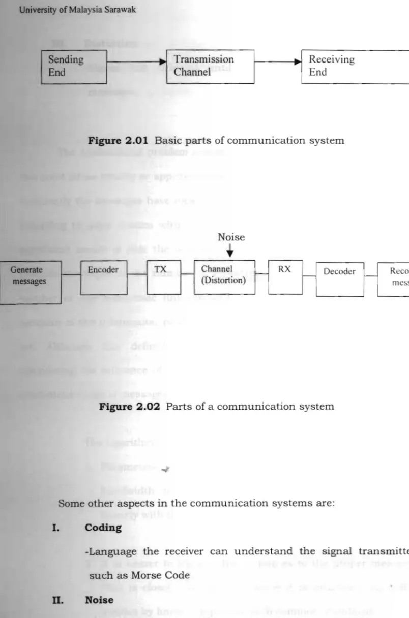
Figure 2.01 Basic parts of communication system
Generate r---messages
Figure 2.02 Parts of a communication system
Some other aspects in the communication systems are:
I. Coding
-Language the receIver can understand the signal transmitted such as Morse Code
D. Noise
-Unwanted random signals added to the original message
6
Sendin
g
Transmission ReceivingEnd
Channel EndNoise
•
Encoder
f - - TX I- Channel ~ RX r - Decoder Record
I-
University of Malaysia Sarawak
fil. Distortion
-Signal that changed until the receiver cannot decode the messages
The fundamental problem of communication is that of reproducing at one point either exactly or approximately a message selected at another point. Frequently the messages have meaning; that is they refer to or are correlated according to some system with certain physical or conceptual entities. The significant aspect is that the actual message is one selected from a set of possible messages. If the number of messages in the set is finite then this number or any monotonic function of this number can be regarded as a measure of the information produced when one message is chosen from the set. Although this definition must be generalized considerably when considering the influence of the statistics of the message and there have a continuous range of messages, use an essentially logarithmic measure.
The logarithmic measure is more convenient for various reasons: 1. Parameters ~of engmeermg importance such as time,
bandwidth, number of relays and many others, tend to vary linearly with the logarithm of the number of possibilities.
2. It is nearer to the intuitive feeling as to the proper measure.
This is closely related to (1) since it is intuitively measures entities by linear comparison with common standards.
University of Malaysia Sarawak
It is mathematically suitable. Many of the limiting operations are
simple in terms of the logarithm but would require clumsy restatement in terms of the number of possibilities. The choice of a logarithmic base
corresponds to the choice of a unit for measunng information. By a
communication system we will mean a system of the type indicated in the communication system. It consists of five parts:
1. An infonnation sources which produce a message to be
communicated to the receiving terminal. The message may be
of various types of signal.
2. A transmitter which operates on the message to produce a
signal suitable for transmission over the channel. In a
multiplex Pulse Code Modulation (PCM) system the different
speech functions must be sampled, compressed, quantized and encoded, and finally interleaved properly to construct the signal.
3. The channel is the medium used to transmit the signal from
transmitter to receiver. It may be a pair of wires, a coaxial
cable, a band of radio frequencies, optical cable and lots more.
University of Malaysia Sarawak
4. The receiver ordinarily performs the inverse operation of that
done by the transmitter and reconstructing the message from
the signal.
5. The destination IS the person for whose the message IS
intended.
2.1.3 Design Considerations
Before starting with the design project, first of all the design
considerations should be discussed. In doing a project, there are few
specifications and considerations that need to be followed. These are the
considerations that must be taken for the practical systems of the
communication system:
(a) Range
For this project, the resulting signal bandwidth is only acceptable
at microwave frequencies. Microwave for line-of-sight links. The
further information has to be transmitted, the more difficult it is
to get the message through uncorrupted.
(b) Power
Transmitted power is always kept to a minimum. The transmitter
power available at microwave frequencies is small and expensive.
University of Malaysia arawak
(c) Cost
The cost has to be kept as low as is compatible with the
achievement of the desired system performance.
(d) Bandwidth
The information will be obtained unless the signal received
contains a small range of frequencies. For telephone channel, the
bandwidth needed is halved at the start by using single sideband
(SSB) techniques and wide enough to recognize the voices. Using
the standard 4KHz of bandwidth voice frequency channel for the
telephone.
(e) Speed
To send information faster, more bandwidth is required but less
time is taken.
(f) Reliability
The aim is to use the cheapest and simplest system that will give
acceptable reproducibility of signal. Narrow bandwidths, low frequencies and intense mUltiplexing can be used.
(g) Convenience
The aspects of convenience occur with the growth of varIOUS
network; the use of larger and more comprehensive integrated
University of Malaysia Sarawak
circuits wherever possible; the need for ease of production and
cheaper repair; and so on.
(h) Accuracy
The more accurate the received information signal must be
compared with the original, the more complex and expensive the
communication system has to be.
2.1.4
Modulation Techniques
over a
Information signals will be carried between a transmitter and a receiver
transmission medium. Modulation is defined as the process of
transforming information from its original form to a form which is acceptable
for transmission. Modulation takes place in the transmitter in a circuit called
modulator. Modulation is an up-shifting of the messages frequencies to a range
more useful for transmission. The selection of the particular modulation
method used is determined by the application intended as well as by the
channel characteristics such as available bandwidth and the susceptibility of
the channel to fading. In order to allow simultaneous uses of the same channel called multiplexing. Each of the unique signals can be assigned a different
carrier frequency but it still shares the same channel. The basic sine wave is
like:
V(t)=V 0 sin (2rcft + cj> )---(2.01)