INFLUENCES OF BRAKE SHOE THICKNESS
AGAINTS DISC BRAKE VIBRATION SYSTEM ON
VARIOUS BRAKING CONDITION
PUBLICATION ARTICLE
Submitted as a Partial Fulfillment of the Requirements for GettingBachelor Degree of Engineering in Automotive Department
Arranged by :
Dwi Aji Saputra
NIM : D 200 102 012
MECHANICAL ENGINEERING PROGRAM STUDY
ENGINEERING FACULTY
INFLUENCES OF BRAKE SHOE THICKNESS AGAINTS DISC BRAKE VIBRATION SYSTEM ON VARIOUS BRAKING CONDITION
Dwi Aji Saputra
Automotive Department of Muhammadiyah University of Surakarta Jln. A. Yani Pabelan-Kartasura. Tromol Pos I Telp. (0271) 715448 Kartasura
Email: [email protected]
ABSTRACT
Abstract :
The aim of this study is to determine the condition of the brake vibration and analyze the
parameters that affect the vibration response occurring. Test was carried out by varying the
thickness of the brake lining. Data taken for thickness of the brake lining (7,5 and 3)mm, with
a variation of the braking pressure 0.6bar and 1bar, shaftrotation (425, 637, 850, and
1061)rpm, the axial and radial direction, vibration measurement used Lutron VB_8202
vibration meter.
Vibration on acceleration measurements show that vibration acceleration in the
radial direction which seems higher when compared to the axial direction, can be in the know
in the axial direction 425 RPM vibration acceleration value is not more than 8.2m / s while the
radial direction up to 11.6m/s .
Increasing the value of amplitude 2-4.7 m/s2 in dictateLessing of Brake pad
worn.The increase in vibration owing to the reduced value of brake lining.
Keywords :Brake, Brake lining thickness, Brake pressure, Damping.
Background
Brakes are an important component
of motor vehicle. Brake function is to
stopping or slowing down. In general, the
vehicle uses hydraulic brake system. The
Components of hydraulic brake are master
cylinder and caliper (cylinder body).
Cylinder Master distributes a braking
pressure from the pedal tocalipers (cylinder
body) through the brake hose. The
caliper (cylinder body) is usedto forward a
hydraulic pressure to brake pad.
Brake works by using
pressureprinciple to slow down the rotation
so that it reveals a friction between the
discs (disc brake) with brake pads. These
friction causes vibration, heat and
noise. Disc roughness and friction
factorstringer the vibration of brake pad and
caliper.
Vibration in the brake components
during operation can cause noise. It comes
from the friction between brake pads that
have been worn by the disc brakes. One of
factors which cause the vibration when
braking operation is worn thin brake
pad. The effects of excessive vibration will
cause inconvenience driving. In addition,
the performance or the operation of the
braking was not optimal.
Brake pad is so extremely important
when braking. It needs special attention to
the condition of the brake pad. Therefore,
there should be a study to determine the
effect of thebrake pads thickness against
the brake disc vibration in the system.
PROBLEM LIMITATION
From above explanation, it can be
taken a problem formulations, namely: how
to influence the thickness of the brake pads
on a range of braking conditions on the
vibration of the disc brake system.
OBJECTIVE
The purpose of this study is
determining the effect of the brake lining
thickness at various braking conditions on
the vibration disc brake system in the form
of changes in the value of the vibration
amplitude.
FORMULATION
To determine the direction of research,
given the extent of the problem as follows:
a. All components of the braking device
is assumed to be at normal
conditions (80% for the master,
calipers, discs and brake hoses).
b. Load conditions are considered
constant.
c. Data Display is only in the form of
vibration amplitude value.
d. At the same braking pressure, the
frictional force is assumed to be the
same for all variations in the
thickness of the brake lining.
The friction coefficient is assumed to be
the same on this test.
LITERATURE REVIEW
Oura (2009), conducted a research on
the mechanism of the appearance of disc
brake squeal vibration.
Carried out research on testing squeal
vibration using Pads with different
thicknesses. The experiment was done with
testing equipment squeal by using brake
pieces with size 20x20 mm with a thickness
variation of the brake lining as testing
material.The experiment was conducted
with dynamic stiffness test apparatus which
was providing a constant pressure. The test
results showed the dynamic stiffness of
Pads became stiff when braking pressure
was increasing, and the stiffness increased
with the thin Pads. Results of the testing
showed the frequency squeal was high
when the stiffness of Pads became hard.
BASIC THEORY
A. Brake Work System
In general, the brake discs are currently
working to apply the principles of
hydraulics. The hydraulic system consists
of a master cylinder, brake calipers, brake
oil reservoir to place and other supporting
on brake master so piston inside brake
master push fluid brake to fluid path, and
then entering to piston chamber brake
caliper. At Outer Piston, brake pad is
installed, this brake pad clamps disc brake
by using piston pressure to outer direction
which is caused by the pressure of brake
fluid so that the friction effect among dsisc
and brake pad are generated braking
process. Frictional forces that occur in the
disc braking system can be explained in the
following figure:
Figure 1. How Disc Brakes Work
(Anonim, 2012)
B. Disc Brake Components
In general, disc brake components
are as follows:
a. Brake Pad
Brake consists of a mixture of fiber and
little metallic iron powder. Generally brake
pad is given lining brake to show the thicks
of brake pad.Thus, the worn of the brake
can be checked easierwhen unloading
brake components. In some brake pads,
the use of metallic plate attached to the
side of the brake piston whose function is to
prevent noise when braking.
Brake is also a major component of the
brake as it serves as a grappling discs so
that the rate of the vehicle can be reduced
and eventually stopped completely, usually
made of composite materials or pasta.
Brake commonly used in today's modern
vehicles is appropriate types of brakes,
whether wearing drum brake or disc brake.
To canvass brake used in generally disc
brake pad or brake disc called a pad, while
used on drum brakes are often called brake
shoe.
Figure 2. Brake Pad
b. Disc
In general, disc brake or disc made of
cast iron and holes for ventilation and
cooling function. Given the age of the brake
ventilation and longer lasting.
Figure 4. Disc
c. Caliper
Caliper is also called a cylinder body,
which functions holds-piston and the
the brake master cylinder of the caliper.
The components contained in the circuit
calipers as follows:
1. Piston
2. Piston Ring
3. Rubber Protector
4. Torque plate
The cause of the vibration on the brake disc (brake pad)
1. Disk disc is not smooth 2. Disc Thickness
3. Unbalance disc
4. Worn disc Brake and Brake pad 5. Dust and dirt.
Brake force this optained from the
friction between Brake pad and disc.
Vibration happens on the brake during
operation is vibration excited or self-excited
vibration where the system generates a
number of excitation that produces
oscillatory motion in the system itself.
Numbers fnis one of the most important in
the amount of vibration analysis and is
called the natural frequency. With the
equation to find the natural frequency of the
brake lining is:
/
With a record of angular frequency ω, with
units of radians per second, often used in
equations because it simplifies the
equations, but the amount is usually
converted into a frequency "standard"
(units of Hz) when stating the frequency of
the system.
Vibration
Vibration is a back and forth motion
within a certain interval. Vibration
associated with the oscillatory motion of
objects and force associated with these
objects. All objects that have mass and
elasticity is able to vibrate, so most
machines and structural engineering
(engineering) experience some degree of
vibration and design requires
consideration of the nature of the
oscillation.
2
The magnitude of we can see the
equation:
2
Displacement deviation can write
as:
Harmonic motion velocity and acceleration
can be obtained by differentiation of
equation by using dot notation for
derivatives, then ;
a. Free Vibration without damping
k
x(t)
F
Figure 2.7. Vibration without dampers
b. Free Vibration with Dampig
Where :
/
k c
x(t)
Figure 2.8 Vibration with damping
Factors affecting the value of the vibration on the brake
a. Stiffness
Stiffness of the structure is an
essential. Restrictions are useful for
maintaining the rigidity of construction so
as not sagged more than the required
deflection. Stiffness is defined as the force
required to obtain one unit of
displacement. Stiffness value is the slope
angle of the relationship between load and
deflection. The more rigid a structure
greater rigidity values.
b. Friction force
Friction is the force that is generated
by two objects rub against each other and
the direction opposite to the motion of
objects. Here is the friction on the beam.
With the equation to calculate the friction
force is:
Fg = .N
Figure 2.11 Friction on the beam
c. Damping
Damping is the absorption of incident
energy (energy dissipation) by a structure
due to various reasons. Some of the
causes include the release of energy by
movement between molecules within the
material, the release of energy by friction
linking devices and systems support, the
release of energy by friction in the air. The
energy release is also the result of plastic
joints. Since the damping function of
energy release then this will reduce the
structural response.
Therefore greatly affect the vibration
damping. Where the damping is strongly m
influenced by the critical damping value
(critical damping), the point at which the
system no longer oscillates. The amount of
attenuation is usually expressed in damping
ratio. The coefficient of damping required to
reach the point of critical damping is:
2 2√ 2
If the value of the damping coefficient to
reach the point of critical damping, then the
system will be difficult muffled. So it is
difficult to stop oscillating system,
consequently a large vibration.
∆ ··
· ∆
·
F F
F F
c
Page 2.12 Deflection axial
Where : ∆
/
...
RESEARCH METHODOLOGY
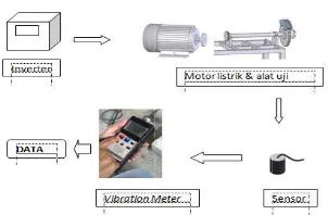
Flow chart diagram
Material and Tools
Tools wich used in this research are as
follows :
a. Brake pad vibration test equipment (with electric motor 3 phase 5,5 HP) b. 3 couple Brake pad with different
thickness (7mm, 5mm, 3mm). c. Piezoelectric Accelerometer.
d. Vibration meter markLutronVB_8202 e. Tachometer.
f. Inverter. g. Pulley dan bel
MAKING OF DATA
Thickness Variation (A = 7, B = 5, C = 3) mm Braking Pressure Variation (0,6, and 1) Bar Variations Rpm (425, 637, 850 and 1061)
START
Making tool vibrations test disc thickness brake Pad
Acceleration value of data vibrations
Analysis
Conclusion
END
k
Af
re 9.Test da
ibration met
Acceleromete
Brake Pad
is complete
d the data
n the followin
ata making s er
er
assembled
collection,
ng
he first ste
with recor
rm of vibratio
lay table in
he excel pro
onnect betw
ess variatio
and also br
e rotation of
natural frequ
ogram into a
ween the
on with rot
raking press
f the motor.
uency of the
kness variat
calculate t
ver beam ro
a processin
ment data
ation data in
program. W
a graph whic
brake linin
tation of th
sure variatio
Measureme
e system eac
tion with th
8.9
425 637 850 1061
RMS
Vibration Graphs on axial direction for pressure 1 bar
Pad 7
Pad 5
Pad 3
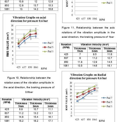
RPM Data And Analysis
Then, the data above are analized to
knowing the vibration at different brake
pressure and shaft rotation speed. Data
measurment shown at following figure :
Rotation (RPM)
Vibration Velocity (m/s²) Thickness
Figure 10. Relationship between the
rotation axes of the vibration amplitude in
the axial direction, the braking pressure of
0.6bar
Rotation (RPM)
Vibration Velocity (m/s²) Thickness
Figure 11. Relationship between the axis
rotations of the vibration amplitude in the
axial direction, the braking pressure of 1bar
Rotation (RPM)
Vibration Velocity (m/s²) Thickness
425 637 850 1061
RMS V
A
LUE
(m/s
2)
Vibration Graphs on axial direction for pressure 0.6 bar
Pad 7
425 637 850 1061
RMS
Vibration Graphs on Radial direction for pressure 0.6 bar
Pad 7
Pad 5
Pad 3
Figure 12. The relationship between the
rotation axis of the vibration amplitude in
the radial direction at a pressure of 0.6bar
Rotation
(RPM)
Vibration velocity (m/s²)
Thickness
Figure 13. Relationship between the axis
rotations of the vibration amplitude in the
radial direction at a pressure of 1bar
Discussion
The results of processing the vibration
acceleration values indicate that an
increase in the value of the acceleration of
vibration generated each variation of the
thickness of the brake lining. This increase
is indicated by the value of the acceleration
of vibration that occurs in brake that has
experienced wear and worn. The results of
the processing vibration indication that the
brake pads are still good or still thick
produces low vibration acceleration value.
From vibration value measurment, we
can find the value of brake pad natural
frequency and critical damping coeficient
which will get result as table below:
Table 1. Values of natural frequencies and
critical damping coefficient value of each
brake pad.
Thick Brake
Pad (mm) (Hz) (Ns/m)
7 493,63 184,61
5 1111,94 373,27
3 4447,92 1352,16
Based on the results of these calculations
with a critical damping coefficient is greater,
and the system will easily vibrate because
of small damping ratio.
On the axial direction of the
measurement pressure of 1 bar (Figure 4.2)
and the measurement of radial pressure of
1 bar (Figure 4.4) it can be seen that the
thickness of the lining 5mm shaft speed
637 rpm surge approaching the vibration
amplitude values even exceed the value of
the amplitude of vibration in the lining
thickness of 3mm.On the measurement of
vibration velocity shows that the vibration of
velocity in the radial direction which
appears larger when compared to the axial
direction, as shown in the graph measuring
the axial direction for the braking pressure
0.6 bar (Figure 10) and radial graphs for
9.6
425 637 850 1061
RMS
Vibration Graphs on Radial direction for pressure 1 bar
Pad 7
Pad 5
Pad 3
braking pressure 0.6 bar (Figure 12) it can
be seen the difference value of the
resonance. 425 rpm for shaft rotation in the
direction of axial value does not exceed 8.2
m/s2, while in the radial direction vibration
reaches the value of 11.6 m/s2. This occurs
due to the effect of centrifugal force on the
rotation axis to the radial direction, so that
the force that occurs on the radial direction
is greater than the axial direction.
Conclusion
From data analysing and discusion can be
of tained conclusion as follow :
1. Increasing the value of aplitude2-4,7
m/s2in dicate lessing of Brake pad
worn.The increasing of aplitude value is
cause by the lessing of pad mass, that
affect the decreasing of damping value
to vibration, then Increasing of braking
pressure and shaft rotation will increase
exitation force that cause the value of
amplitude greater.
Sugesstion
1. Next, we can do research to detect the
level of brake pad worn using other
brand.
2. Before take the data, it is better to know
the brake resonansi frequency.
Sugegestion
Untuk selanjutnya dapat di lakukan
penelitian untuk mendeteksi tingkat
keasuan kampas rem cakram
dengan bahan atau merk yang
berbeda.
Sebelum pengambilan data
henaknya mengetahui frekuensi
References
Aji, K., 2007, Deteksi Kerusakan Bantalan Gelinding Pada Pompa Sentrifugal Dengan
Analisa Sinyal Getaran. Jurusan Teknik Mesin, Fakultas Teknik Universitas
Sebelas Maret, Surakarta.
Anonim., 2012, Automotif Diagnostic & Repair Help for Cars and Trucks.
Hidayat, L.L.R. G., 2009,Perawatan prediktif Penerapan Getaran Mekanis.LPP UNS dan
UNS Press,Surakarta.
http: //yefrican.files.wordpress.com, 20thFebruary 2014
http://www.sensotec.com/accelerometer_fag.asp?category=A11#,20thFebruary 2014
http: // id.wikipedia.org/wiki/Rem, 20thFebruary 2014
Jaya, S.M., 2009, Analisis Getaran dan Suara Pada Rem Cakram Saat Beroperasi.Jurusan
Teknik Mesin, Fakultas Teknik Universitas Andalas.Sugiharto,A., 2007,Cara Kerja
dan Perbaikan Rem Disc Brake,Lembaga Penelitian-UNES,Semarang.Oura, Y.,
Kurita, Y., and Matsumura, Y., 2009,Influence of dynamic stiffness in contact
region on disk brake squeal.Department of Mechanical Engineering, The
University of Shiga Prefecture, 2500 Hassaka-cho, Hicone-shi, Shiga, 522-8533,
Japan.
Oura, Y., Kurita, Y., and Matsumura, Y., 2009,Influence of dynamic stiffness in contact
region on disk brake squeal.Department of Mechanical Engineering, The
University of Shiga Prefecture, 2500 Hassaka-cho, Hicone-shi, Shiga, 522-8533,
Japan.
Oura, Y., Kurita, Y., Nishizawa, Y., and Kosaka, K., 2010,Influence of brake pad thickness
on disk brake squeal.Department of Mechanical Engineering, The University of
Shiga Prefecture, 2500 Hassaka-cho, Hicone-shi, Shiga, 522-8533, Japan.
Rao, S., Singeresu, Mechanical Vibration.
Sawczuk,W.,2011,Application of Vibroacoustic Signal to Diagnose Disck Braking
System,Journal of KONES Powertrain and Transport, vol. 18,No. 1 2011.
Wiliam T., 1986, Teori Getaran Dengan Penerapan Edisi Kedua, Penerbit Erlangga,