Sr. No
Topic
1.
Scope of the Journal
2.
The Model
3.
The Advisory and Editorial Board
4.
Papers
First Published in the United States of America. Copyright © 2012
Foundation of Computer Science Inc.
International Journal of Computer Applications (IJCA) creates a place for publication of papers which covers the frontier issues in Computer Science and Engineering and their applications which will define new wave of breakthroughs. The journal is an initiative to identify the efforts of the scientific community worldwide towards inventing new-age technologies. Our mission, as part of the research community is to bring the highest quality research to the widest possible audience. International Journal of Computer Applications is a global effort to consolidate dispersed knowledge and aggregate them in a search-able and index-able form.
The perspectives presented in the journal range from big picture analysis which address global and universal concerns, to detailed case studies which speak of localized applications of the principles and practices of computational algorithms. The journal is relevant for academics in computer science, applied sciences, the professions and education, research students, public administrators in local and state government, representatives of the private sector, trainers and industry consultants.
Indexing
International Journal of Computer Applications (IJCA) maintains high quality indexing services such as Google Scholar, CiteSeer, UlrichsWeb, DOAJ (Directory of Open Access Journals) and Scientific Commons Index, University of St. Gallen, Switzerland. The articles are also indexed with SAO/NASA ADS Physics Abstract Service supported by Harvard University and NASA, Informatics and ProQuest CSA Technology Research Database. IJCA is constantly in progress towards expanding its contents worldwide for the betterment of the scientific, research and academic communities.
Topics
Open Review
International Journal of Computer Applications approach to peer review is open and inclusive, at the same time as
it is based on the most rigorous and merit-based ‘blind’ peer-review processes. Our referee processes are
criterion-referenced and referees selected on the basis of subject matter and disciplinary expertise. Ranking is based on clearly articulated criteria. The result is a refereeing process that is scrupulously fair in its assessments at the same time as offering a carefully structured and constructive contribution to the shape of the published paper.
Intellectual Excellence
includes members of research center heads, faculty deans, department heads, professors, research scientists, experienced software development directors and engineers.
Dr. T. T. Al Shemmeri, Staffordshire University, UK Bhalaji N, Vels University
Dr. A.K.Banerjee, NIT, Trichy Dr. Pabitra Mohan Khilar, NIT Rourkela
Amos Omondi, Teesside University Dr. Anil Upadhyay, UPTU
Dr Amr Ahmed, University of Lincoln Cheng Luo, Coppin State University
Dr. Keith Leonard Mannock, University of London Harminder S. Bindra, PTU
Dr. Alexandra I. Cristea, University of Warwick Santosh K. Pandey, The Institute of CA of India
Dr. V. K. Anand, Punjab University Dr. S. Abdul Khader Jilani, University of Tabuk
Dr. Rakesh Mishra, University of Huddersfield Kamaljit I. Lakhtaria, Saurashtra University
Dr. S.Karthik, Anna University Dr. Anirban Kundu, West Bengal University of
Technology
Amol D. Potgantwar, University of Pune Dr Pramod B Patil, RTM Nagpur University
Dr. Neeraj Kumar Nehra, SMVD University Dr. Debasis Giri, WBUT
Dr. Rajesh Kumar, National University of Singapore Deo Prakash, Shri Mata Vaishno Devi University
Dr. Sabnam Sengupta, WBUT Rakesh Lingappa, VTU
D. Jude Hemanth, Karunya University P. Vasant, University Teknologi Petornas
Dr. A.Govardhan, JNTU Yuanfeng Jin, YanBian University
Dr. R. Ponnusamy, Vinayaga Missions University Rajesh K Shukla, RGPV
Dr. Yogeshwar Kosta, CHARUSAT Dr.S.Radha Rammohan, D.G. of Technological
Education
T.N.Shankar, JNTU Prof. Hari Mohan Pandey, NMIMS University
Dayashankar Singh, UPTU Prof. Kanchan Sharma, GGS Indraprastha
Vishwavidyalaya
Bidyadhar Subudhi, NIT, Rourkela Dr. S. Poornachandra, Anna University
Dr. Nitin S. Choubey, NMIMS Dr. R. Uma Rani, University of Madras
Rongrong Ji, Harbin Institute of Technology, China Dr. V.B. Singh, University of Delhi
Anand Kumar, VTU Hemant Kumar Mahala, RGPV
Prof. S K Nanda, BPUT Prof. Debnath Bhattacharyya, Hannam University
Dr. A.K. Sharma, Uttar Pradesh Technical University
Dr A.S.Prasad, Andhra University
Rajeshree D. Raut, RTM, Nagpur University Deepak Joshi, Hannam University
Dr. Vijay H. Mankar, Nagpur University Dr. P K Singh, U P Technical University
Atul Sajjanhar, Deakin University RK Tiwari, U P Technical University
Navneet Tiwari, RGPV Dr. Himanshu Aggarwal, Punjabi University
Ashraf Bany Mohammed, Petra University Dr. K.D. Verma, S.V. College of PG Studies & Research
Totok R Biyanto, Sepuluh Nopember R.Amirtharajan, SASTRA University
Sheti Mahendra A, Dr. B A Marathwada University Md. Rajibul Islam, University Technology Malaysia
Koushik Majumder, WBUT S.Hariharan, B.S. Abdur Rahman University
Dr.R.Geetharamani, Anna University Dr.S.Sasikumar, HCET
Rupali Bhardwaj, UPTU Dakshina Ranjan Kisku, WBUT
Gaurav Kumar, Punjab Technical University A.K.Verma, TERI
Prof. B.Nagarajan, Anna University Vikas Singla, PTU
Dr H N Suma, VTU Dr. Udai Shanker, UPTU
Anu Suneja, Maharshi Markandeshwar University Prof. Rachit Garg, GNDU
Aung Kyaw Oo, DSA, Myanmar Dr Lefteris Gortzis, University of Patras, Greece.
Suhas J Manangi, Microsoft Mahdi Jampour, Kerman Institute of Higher Education
and IT, Govt. of India Technology of China
Prof. Surendra Rahamatkar, VIT Prof. Shishir K. Shandilya, RGPV
M.Azath, Anna University Liladhar R Rewatkar, RTM Nagpur University
R. Jagadeesh K, Anna University Amit Rathi, Jaypee University
Dr. Dilip Mali, Mekelle University, Ethiopia. Dr. Paresh Virparia, Sardar Patel University
Morteza S. Kamarposhti , Islamic Azad University of Firoozkuh, Iran
Dr. D. Gunaseelan Directorate of Technological Education, Oman
Dr. M. Azzouzi, ZA University of Djelfa, Algeria. Dr. Dhananjay Kumar, Anna University
Jayant shukla, RGPV Prof. Yuvaraju B N, VTU
Dr. Ananya Kanjilal, WBUT Daminni Grover, IILM Institute for Higher Education
Vishal Gour, Govt. Engineering College Monit Kapoor, M.M University
Dr. Binod Kumar, ISTAR Amit Kumar, Nanjing Forestry University, China.
Dr.Mallikarjun Hangarge, Gulbarga University Gursharanjeet Singh, LPU
Dr. R.Muthuraj, PSNACET Mohd.Muqeem, Integral University
Dr. Chitra. A. Dhawale, Symbiosis Institute of Computer Studies and Research
Dr.Abdul Jalil M. Khalaf, University of Kufa, IRAQ.
Dr. Rizwan Beg, UPTU R.Indra Gandhi, Anna University
V.B Kirubanand, Bharathiar University Mohammad Ghulam Ali, IIT, Kharagpur
Dr. D.I. George A., Jamal Mohamed College Kunjal B.Mankad, ISTAR
Raman Kumar, PTU Lei Wu, University of Houston – Clear Lake, Texas.
G. Appasami , Anna University S.Vijayalakshmi, VIT University
Dr. Gurpreet Singh Josan, PTU Dr. Seema Shah, IIIT, Allahabad
Dr. Wichian Sittiprapaporn, Mahasarakham University, Thailand.
Chakresh Kumar, MRI University, India
Dr. Vishal Goyal, Punjabi University, India Dr. A.V.Senthil Kumar, Bharathiar University, India
An Ontology in Project Management Knowledge Domain
Authors : T.Sheeba, Reshmy Krishnan, M.Justin Bernard
1-7
Design and Implementation of a Robot for Maze-Solving using Flood-Fill Algorithm
Authors : Ibrahim Elshamarka , Abu Bakar Sayuti Saman
8-13
Efficient Content Discovery in P2P-Multimedia System
Authors : V. Kavitha Chandrakanthan, R. Raj Priyadarshini
14-17
Hospital Information Sharing based on Social Network Web
Authors : Yudhistira Adi Nugraha Paturusi, I Made Sukarsa, I Gusti Made Arya Sasmita
18-24
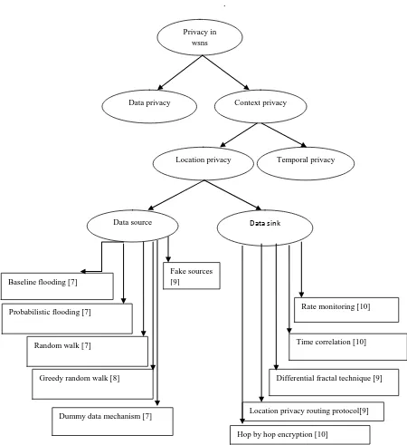
Protecting Location Privacy in Wireless Sensor Networks against a Local Eavesdropper – A Survey
Authors : Chinnu George, Dhinakaran Nathaniel
25-29
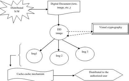
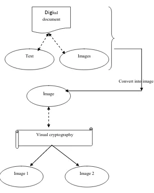
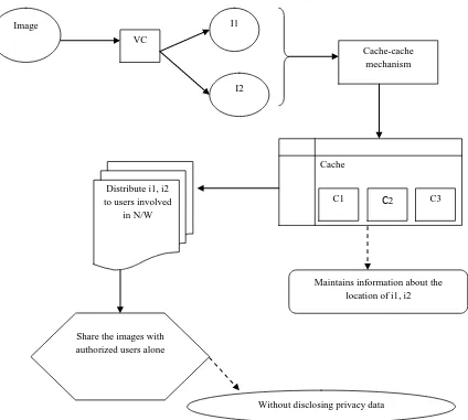
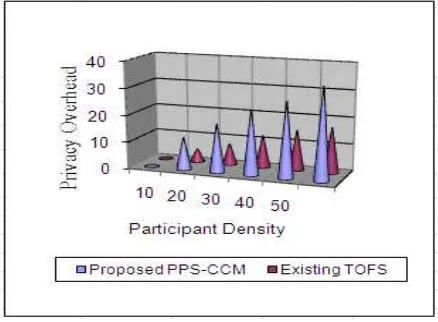
Efficiency Privacy Preservation Scheme for Distributed Digital Document using Cache-Cache Mechanism
Authors : Shiny Malar F.R., Jeya Kumar M.K
30-38
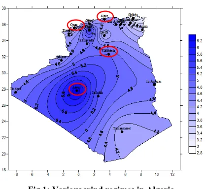
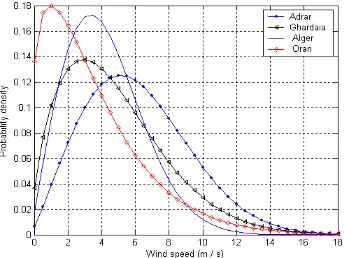
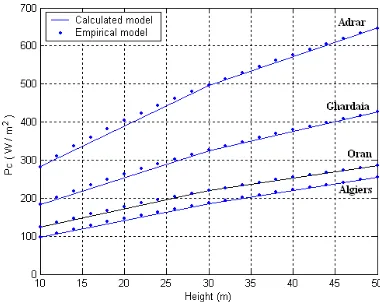
Wind Characteristics Analysis for Selected Site in Algeria
Authors : Maouedj Rachid, Diaf Said, Benyoucef Boumediene
39-46
Comprehensive Exploration for Proposing Hybrid Scheme upon Congestion Avoidance Algorithms
Authors: Wasai Shadab Ansari , Ijaz Ali Shoukat , Atif M. AlAmri , Abdullah Al-Dhelaan , Mohsin Iftikhar , Mudassar Ayub, Mohammad Serajuddin.
47-55
An Ontology in Project Management Knowledge Domain
T.Sheeba,
Muscat College, P.O.Box:2910, P.C:112, Ruwi, Sultanate of Oman
Reshmy Krishnan,
PhD. Muscat College, P.O.Box:2910, P.C:112, Ruwi, Sultanate of OmanM.Justin Bernard,
W.J. Towell Engineering, P.O.BOX:1040, P.C:112, Ruwi, Sultanate of Oman
ABSTRACT
E-Learning is a process in which electronic medium is used to access the defined set of applications and processes. In e-Learning environment, automatic classification of learning
materials isessential due to lack of common vocabulary of the
knowledge area in some context.Ontology has the potential to
play an important role in representing an area of knowledge. This paper proposes ontology to automatic classification of learning materials to the Project Management knowledge area domain. This ontology aims to facilitate the search for learning materials within the given domain. The Project Management Body of Knowledge (PMBOK) was used to define the hierarchical structures of knowledge as it is intended to cover broad area of Project Management. The Rational Unified Process (RUP) was used to add axioms to define the relationships between the main concepts. Two specific examples were designed to show the automatic classification of learning materials. Experiments were performed using the OWL reasoner Pellet and editor Protégé 4.2 alpha version. The results of our performance evaluation show that the ontology is able to classify and locate learning materials from the Project Management area, according to the desired area, role, artifact and activity.
Keywords
Ontology; PMBOK; RUP; Project Management; Protégé 4.2 alpha
1.
INTRODUCTION
With the development of World Wide Web (WWW), the increased popularity and use of its new web-based technologies has increased the number of learning environments, from simple learning resources repositories to more complex learning environments. In such learning environments, almost all the resources are provided through the computers and networks and students can learn anytime and anywhere. It can provide flexible and user-oriented learning environments to students [1].
This self-learning process can happen through many learning materials, such as slide shows, digital books, audio or video recordings, etc. These materials are designed for both on site and at distance learners to use on their own. It allows knowledge sharing within a common interest domain and stimulates independent learning. Project Management can be named as one of such subjects.
However, the self-learning environment can be challenging, even for the brightest and most motivated students in real knowledge acquisition. The difficulty in finding the desired
learning materials according to the learner’s range of
knowledge themes and interest is one of these challenges.
Classification of learning materials according to their knowledge area scheme improves the accuracy of information retrieval significantly and allows users to browse the
collection by subject. However, these classification
mechanisms must use a common language that would allow knowledge sharing to occur effectively. The automated classification is relevant when people do not hold enough knowledge to identify the theme related to the learning materials due to lack of common vocabulary of the knowledge area [2]. Project engineers can be mentioned as an example.
Most knowledge areas as an example, the Project Management area have terminology problems. A terminology, as a general term for all kinds of controlled vocabularies, can help to clear up ambiguities in the terms used in the context of project management [3]. It is common that different development teams use different terms for the same concepts. Thus, it is likely that even professionals find some difficulty to search adequate learning materials due to lack of a common terminology.
In this context, ontologies have the potential to play an important role in defining the terms used to describe and represent an area of knowledge thus providing a common shared understanding of the structure of information among individuals or organizations, to enable reuse of domain knowledge, make domain assumption explicit, to separate domain knowledge from the operational knowledge and to analyze domain knowledge. It includes machine-interpretable definitions of basic concepts in the domain and relations among them [4].
Ontology describes a hierarchy of concepts related by subsumption relationships, suitable axioms are added in order to express relationships between concepts and to constrain their intentional interpretations. Ontologies can be used to describe a common vocabulary of terms and specification of
their meaning to the knowledge area [5]. Through ontologies,
hierarchical structures of themes related to the learning materials can be defined and also it is possible to add reasoning to this structure in order to help the automatic classification of learning materials within the defined hierarchy.
The main objective of this paper is to propose an ontology to automatic classification of learning materials related to the Project Management knowledge area. Also, this ontology aims to facilitate the search for learning materials within the given domain. The Project Management Body of Knowledge (PMBOK) [6] was used to define the hierarchical structures of knowledge. The absence of a recognized consensus on Project Management terminology has been a challenging task in building the PMBOK Guide, and in achieving an international consensus. The PMBOK is intended to cover broad area of
Project Management. The Rational Unified Process (RUP)
was used to add axioms to define the relationships between the main concepts and enable the reasoning to the PMBOK knowledge area.
ontology for the classification of learning materials according to the PMBOK knowledge areas; Section 4 discuss some case studies and Section 5 concludes the paper.
2.
RELATED WORK
There are several papers proposing ontologies for the Project Management area. This section presents these researches and their approaches.
PROMONT [7], is a project management ontology developed from the most notably upcoming DIN 69901 model to model project management specifications. It provides the basis of common understanding between projects related terms and methods and thus facilitate the management of projects accomplished in dynamic virtual environments.
A prototype ontological model [8] prescribed by the PRINCE2® project management method is described for the project management processes. This prototype creates a representation of ontology in OWL as a collection of axioms. It was created using the Protégé 4 ontological modeling tool. This model is used in checking the compliance of suppliers stated methods with standards and supporting process model tailoring. However, it presents difficulties for domain experts as its reasoning rules can be counter-intuitive.
The concepts of e-Government project management are presented using ontology in this model [9]. It is applied in the productivity of e-Government project process which enables the knowledge reuse, collaboration and interoperability between all stakeholders related with the implementation of such type of projects.
PMBOK integrated with RUP is applied to create a model for software project management [10]. This integrated model addresses the possibility of automating a number of tasks for software development.
HCRN (hierarchical case retrieval network) [11] is used by the project managers to interlink decision making tasks. It provides a basis for experience management of decision making within project management processes by transforming decision situation to knowledge focus.
As there are several schemes proposed for ontologies in the Project Management area, there is not an ontology to classify materials according to the Project Management Engineering knowledge area. The next section discusses the proposal of an ontology to help solving this problem.
3.
PROPOSED ONTOLOGY
This section presents an ontology for software Project Management based on PMBOK and its integration with RUP concepts to classify learning materials in the Project Management knowledge area. Some of the widely used
ontology development tools include Ontolingua, Ontosaurus,
WebOnto, Protégé, OntoEdit etc. In this area of ontology
development, ontology editor Protégé 4.2 alpha is used as an appropriate language and development tools as it is widely
available.
The most prevalent Project Management document is the Project Management Body of Knowledge (PMBOK) provided by the Project Management Institute with the objective of serving as reference to Project Management related courses.
PMBOK’s knowledge area is used as a reference in this paper
to define the Project Management knowledge’s hierarchical
structure. This guide identifies a comprehensive set of Project
Management definitions which are “good practice” and
“generally recognized”. They are organized into five generic
process groups and nine Project Management knowledge areas (shown in Table 1), which determine the scope of what is generally understood to be Project Management [7].
However, the guide does not have enough information that allows automatic classification of learning materials according to the hierarchical structure defined for Project Management. Also, PMBOK does not provide a discipline approach to assign tasks and responsibilities of knowledge areas using relationships among concepts or precise properties within the Project Management area. Hence, RUP was also used to define the relationships among the main concepts, which are: Discipline, Role, Artifact and Activity. Although RUP is a software engineering process, the concept of discipline can be related to PMBOK knowledge areas, as shown in Table 1.
Table 1. Relationship between the PMBOK knowledge areas and RUP disciplines
PMBOK
Knowledge Area RUP Discipline
Project Integration
Management
Project Management
Requirements
Deployment
Configuration & Change Management
Project Scope Management
Project Management Requirements
Configuration & Change Management Project Time
Management Project Management
Project Cost
Management Project Management
Project Quality Management
Project Management
Configuration & Change Management Project Human
Resource Management
Project Management
Project
Communications Management
Project Management
Project Risk
Management Project Management
Project Procurement Management
Requirements
3.1
Development of Ontology
There is no one “correct” way or methodology for developing ontologies. The method for development of ontologies proposed by [4] is followed in this paper. According to the proposed approach, ontology development involves the following six basic steps. The general stages in the design and development of ontology are as follows:
Step 1 - ENUMERATE IMPORTANT TERMS IN
ONTOLOGY
To build a glossary for Project Management, we collected the terms from PMBOK and software development area.
Step 2 - DEFINE THE CLASSES AND THE CLASS
HIERARCHY
The main goal of this step is the creation of a set of preliminary concepts and the categorization of those terms into concepts. Using the top-down strategy we tried to fit the terms and concepts into the metaconcept.
Steps 3 & 4 - DEFINE THE PROPERTIES OF CLASSES
– SLOTS, DEFINE THE FACETS OF THE SLOTS
Step 5: GENERATION OF INSTANCE
3.2
OnrepRUP: Ontology Representation
of RUP
RUP expresses each discipline in terms of its key elements: roles (who performs activities which have input and output artifacts), activities (how they perform the tasks), and artifacts (what the activity achieves). A role defines the behavior and responsibilities of an individual, or a set of individuals working together as a team. It provides general description of the role and the artifacts and activities for which the role is responsible. An activity is a piece of task a role performs. It describes the role responsible for the activity and the artifact(s) needed as input and the artifact(s) produced as output. An artifact is a document, model, or model element produced, modified, or used by a process. It describes the role responsible for artifact. Other elements supplement these three key elements, such as work guidelines, artifact guidelines, concepts, templates, reports, checkpoints, whitepapers, roadmaps and tool mentors [12].
OnrepRUP was developed with Discipline concept and its relationship to the key concepts Artifact, Role and Activity. Relationships and their properties created for these four concepts are shown in Table 2.
Table 2. Classes and properties from OnrepRUP
The general proposed hierarchy is presented in Fig 1. The PMLearningMaterial class was created to group the PMBOK knowledge areas. RupCoreElements class was created to group the derivative concept classes: Discipline, Artifact, Role and Activiy.
Fig 1: OnrepRUP general hierarchy
The Discipline class consists of nine disciplines that represent the RUP model. Discipline class and other classes Activity, Role and Artifact are represented by the relation
“isDomainOf” as shown in Fig 2.
Fig 2: Discipline class
Similarly, classes Artifact, Role and Activity were related to
the Discipline class using “hasDomain” property. Fig 3 shows
an example of “hasDomain” property relating Artifact and
Discipline classes. Subclasses of artifact identify each of nine disciplines proposed in the RUP model using this relationship.
Domain Class
Range
Class Property
Special Property (inverse)
Artifact Task Role
Disciplin
e hasDomain isDomainOf
Disciplin e
Artifact Task Role
isDomainOf hasDomain
Role Artifact
hasConsult
hasResponsible isConsultedBy
isResponsibleFor
Artifact Role isConsultedBy
isResponsibleFor
hasConsult hasResponsible
Role Activity hasPerform IsPerformerOf
Fig 3: hasDomain property
The Role class consists of six group of roles created within the RUP, namely: Analysts, Developers, General Roles, Manager, Production Support and Testers. Furthermore, instance of each roles are related to the instance of Artifact
using two relationships “hasConsult” and “hasResponsible” as
shown in Fig 4.
Fig 4: Relation between Role’s subclasses and Artifact
The Activity class was created to represent the activity of the RUP model. The Activity class has direct relationship with the
Role class through the “hasPerform” property as shown in Fig
5.
Fig 5: Relation between Role’s subclasses and Activity
3.3
Project
Management
Learning
Materials Ontology
After the ontology structure for RUP elements are established, it is then necessary to enable automatic classification of learning materials within Project Management domain. The PMLearningMaterial class was created to represent the Project Management learning materials which represent the
ten PMBOK’s areas. Each PMBOK’s areas are assigned to the
instance of learning material, as shown in Fig 6.
Fig 6: Learning Materials according to the PMBOK
In order to recommend the learning material to the three
concepts Artifact, Role and Activity “isRecommendedTo”
property was created. Below table shows the relation of three concepts Artifact, Role and Activity to the learning material using “isRecommendedTo” property.
Table 3. isRecommendedTo property
Domain Class
Range Class
Property Special Property (inverse)
LearningM aterial
Artifact Activity Role
isRecommen dedTo
hasRecomm endation
Artifact Activity Role
LearningM aterial
hasRecomme ndation
isRecomme ndedTo
Through the related recommendation it is possible to classify the material according to the PMBOK’s knowledge areas. Thus, it is possible to recommend the learning material for the use of a specific artifact, such as a Use cases; the execution of a specific activity, such as Develop iteration plan; or the execution of a specific role, such as Software Analyst. For example, a learning material will be classified to atleast one instance of the Artifact, Role or Activity classes using the
Fig 7: isRecommendedTo Property
This type of recommendation helps to obtain a precise classification of learning materials when there is no formal knowledge about to which knowledge area the material belongs to.
4.
Results
The proposed ontology could be used in the e-learning
environment to share the knowledge related to the Project Management area. This ontology will help the project engineers in two areas. First, it will help to classify the learning materials within the appropriate domain as the user may not have enough knowledge to classify the correct materials. Second, it will assist to recommend the learning materials within the domain. These two cases have been explained with help of proposed ontology in the following sections. The simulations were created using the Protégé 4.2
alpha tool. The Pellet reasoner was used to classify the
learning materials.
Case 1 – Learning Materials Classification
Project Management learning material instances are added in
the Protégé, as shown in Fig 8. Also “isRecommendedTo”
property was used to make recommendations to the instances of three classes Artifact, Role and Activity.
Fig 8: Learning materials instances included using Protégé
Below table shows the values assigned to the
“isRecommendedTo” property for each one of the learning
materials.
Table 4. Values assigned to the “isRecommendedTo” property
Id. Material
Recommend ation for
Artifact
Recommend ation for
Role
Recommend ation for
Activity
Learning Material 001
Programming Guidelines
Requirements Reviewer
Learning Material 002
Risk List Update
Change Request Learning
Material 003
Test Designer
System Administrator Learning
Material 004
Develop Business Case
Schedule and Assign Work Learning
Material 005
User Interface Guidelines
Learning Material 006
Measurement Plan
Learning Material 007
Report Status
Learning Material 008
Review Record
Software Development Plan (Training-Plan) Learning Material 009
Project Plan (updated)
Learning Material 010
System Analyst
It is possible to verifyfor the learning materials by knowledge
areas defined in the PMBOK as shown in Fig 9. The learning materials are classified in three knowledge areas, one of them by artifact recommendation, and the other two by Role and Activity. The proposed ontology can be used to help filter consistent recommendations among Artifact, Role and Activiy classes.
Fig 9: Learning Materials classification
Case 2 – Learning Materials Recommendation
Case 2 allows the users to find all the learning materials according to the recommendations done by the three classes Artifact, Role and Activity.
SPARQL was used to simulate a sample of these cases possibilities. The SPARQL is an RDF query language, that is, a query language for databases, able to retrieve and manipulate data stored in Resource Description Framework format [13]. Fig 10 shows the result obtained using SPARQL query which retrieves learning materials recommended by Roles.
Fig 10: Query using SPARQL by Role
Queries can be executed to obtain learning materials recommended by Artifacts and Activity as well as shown in Fig 11 and 12.
Fig 11: Query using SPARQL by Artifact
Fig 12: Query using SPARQL by Activity
It is also possible to add new recommendations to the learning materials according to the use. For example, a learning material that was added with the Requirement Reviewer role may also be recommended to the Programming Guidelines Artifact. Hence, the detail for the recommendation and retrieval of material becomes more efficient and precise.
5.
Conclusion
This paper proposed an ontology to automatically classify learning materials related to the Project Management knowledge area. Main structure of PMBOK knowledge area was used to define the ontology. RUP was used to define the concept and relationships among three classes Artifact,
Activity and Role. The RUP was used to add axioms to
represent the relationships between concepts and enable the reasoning to the PMBOK knowledge area according to recommendations. It aims to facilitate the search for these materials.
The proposed ontology will be integrated to a self-learning environment, and experiments with Project Management
students and professionals will be performed in order to
evaluate the proposal.
6.
References
[1] Wei Hu, Tianzhou Chen, and Qingsong Shi,
“Collaborative Web-Based E-learning Environment for
Information Security Curriculum” World Academy of
Science, Engineering and Technology, 53, 2009.
[2] Joselaine Valaski, Andreia Malucelli, Sheila Reinehr,
Ricardo Santos,”Ontology to Classify Learning Material
in Software Engineering Knowledge Domain”, 2011.
[3] Cornelius Wille, Alain Abran, Jean Marc Desharnais,
Reiner R. Dumke,” The quality conceps and subconcepts
in SWEBOK: An ontology challenge”, 2003.
[4] Noy, N. F. and McGuinness, D. L. “Ontology
Development 101: A Guide to Creating Your First
Ontology”. Stanford Knowledge Systems Laboratory
Technical Report KSL-01-05 and Stanford Medical Informatics Technical Report SMI-2001-0880, 2001.
[5] Guarino, N,” Formal Ontology and Information
Systems”, (pp. 3-15). Amsterdam, Netherlands: IOS
Press, 1998.
[6] Duncan, W. R.; A Guide to the Project Management
Body of Knowledge, PMI Standards Committee, Project Management Institute, 1996.
[7] Sven Abels, Frederik Ahlemann, Axel Hahn, Kevin
Hausmann, and Jan Strickmann,” PROMONT – A
Project Management Ontology as a Reference for Virtual
Project Organizations”, OTM Workshops, LNCS 4277,
pp. 813 – 823, 2006.
[8] Robert T. Hughes,”Project management process
ontologies: a proof of concept”, 2010.
[9] Sarantis, D. Askounis, D., “A project management
ontology as a reference for e-Government projects”
Internet Technology and Secured Transactions, 978-1-4244-5647-5, ICITST, 2009.
[10]Daniel Antonio Callegari, Ricardo Melo Bastos, “Project
Management and Software Development Processes: Integrating RUP and PMBOK”, International Conference on Systems Engineering and Modeling,IEEE, 2007.
[11]Maya Kaner and Reuven Karni, ”Experience
Management within Project Management Processes”, 2001.
[12]PRJ270: Essentials of Rational Unified Process, Module
3: RUP Structure and Navigation, PPT Presentation, accessed 2012.
[13]SPARQL: http://en.wikipedia.org/wiki/SPARQL,
accessed June 2012.
[14]Stanford. “The Protégé Ontology Editor and Knowledge
Acquisition System”,
http://protege.stanford.edu/index.html, accessed June
Design and Implementation of a Robot for Maze-Solving
using Flood-Fill Algorithm
Ibrahim Elshamarka
Department of Electrical and Electronic Engineering Universiti Teknologi PETRONAS
31750 Seri Iskandar Malaysia
Abu Bakar Sayuti Saman
Department of Electrical and Electronic Engineering Universiti Teknologi PETRONAS
31750 Seri Iskandar Malaysia
ABSTRACT
Autonomous navigation is an important feature that allows a mobile robot to independently move from a point to another without an intervention from a human operator. Autonomous navigation within an unknown area requires the robot to explore, localize and map its surrounding. By solving a maze, the pertaining algorithms and behavior of the robot can be studied and improved upon. This paper describes an implementation of a maze-solving robot designed to solve a maze based on the flood-fill algorithm. Detection of walls and opening in the maze were done using ultrasonic range-finders. Algorithm for straight-line correction was based on PI(D) controller. The robot was able to learn the maze, find all possible routes and solve it using the shortest one.
General Terms
Autonomous navigation, maze-solving, flood-fill algorithm, ultrasonic sensor, PI(D) controller.
Keywords
Mobile robot, obstacle avoidance, microcontroller.
1.
INTRODUCTION
In mobile robotics, autonomous navigation is an important feature because it allows the robot to independently move from a point to another without a tele-operator. Numerous techniques and algorithms have been developed for this purpose, each having their own merits and shortcomings [1-3,8].
Maze-solving – although artificial in terms of the confine that
the robot it subjected to – is a structured technique and
controlled implementation of autonomous navigation which is sometimes preferable in studying specific aspect of the problem [1]. This paper discusses an implementation of a small size mobile robot designed to solve a maze based on the flood-fill algorithm.
The maze-solving task is similar to the ones in the MicroMouse competition where robots compete on solving a maze in the least time possible and using the most efficient way. A robot must navigate from a corner of a maze to the center as quickly as possible. It knows where the starting location is and where the target location is, but it does not have any information about the obstacles between the two. The maze is normally composed of 256 square cells, where the size each cell is about 18 cm × 18cm. The cells are arranged to form a 16 row × 16 column maze. The starting location of the maze is on one of the cells at its corners, and the target location is formed by four cells at the center of the maze. Only one cell is opened for entrance. The requirements of maze walls and support platform are provided in the IEEE standard [2,3].
2.
RELATED WORKS
Dang and Song proposed “An Efficient Algorithm for Robot
Maze-Solving” which was based on flood-fill algorithm but
improved by reducing some steps not needed in certain cases. As there are channels in the maze where the robot is forced to go only straight forward, when the robot is inside these channels, it does not need to perform all four steps of maze-solving which is updating the wall, flooding the maze, determining which turn to be taken and moving to the next cell. To reduce execution time, it only flood the maze when there is a turn [4].
“Partition-central Algorithm” is another maze-solving
algorithm where the standard 16×16 unit maze is virtually divided into twelve partitions. The robot uses data such as its direction and its current location to change between exploring rules to save more time and optimize the solving process. A simulation was developed to verify the algorithm. Test results
show that partition–central algorithm has higher average
efficiency when compared to other algorithms [5].
In another study, the discretely assigned potential levels were discussed. Using these potential levels, the robot can effectively make autonomous decisions to reach the goal. It demonstrates the method of assigning and controlling these artificial potentials to provide the most optimized path choices while keeping the integrity of the potentials. The basic algorithm is improved by saving information from previous decisions that have been made [6].
3.
THE MAZE AND THE ROBOT
The maze designed for the robot to solve is of the size of 6×6 cells as shown in Figure 1. The actual maze constructed, as
shown in Figure 2, has a physical size of about 2.25 m2. The
maze was designed so that it will have two paths in order for it to be solved. One of the paths is longer than the other. The robot (Figure 3) must decide which one of the paths is shorter and solve the maze through that path.
Fig 2: The maze
Fig 3: The robot
4.
ALGORITHM
Choosing an algorithm for the maze robot is critical in solving the maze. In this exercise, flood-fill algorithm was chosen to solve the maze due to its balance in efficiency and complexity. There are four main steps in the algorithm: Mapping, Flooding, Updating and Turning [2, 6-7]; which are described in the following sub-sections.
4.1
Mapping The Maze
For the robot to be able to solve the maze, it has to know how big the maze is and virtually divides them into certain number of cells that can be used later in calculating the shortest path to the destination. In this project, a maze of 6×6 cells is used. Between two cells there can be a wall. Thus, in a row of six cells, there are five walls in between them. In total, in a row, there are eleven units of cells or walls. This information is stored in an 11×11 array, as shown in Figure 4. The white units are the cells which the robot can be placed inside. The orange units are the locations for potential walls. The black units indicate wall intersections which are ignored by the algorithm. The external borders of the maze are also ignored as they are fixed boundaries of the maze. Both cells (white) and walls (orange) are set to zero in as their initial conditions.
Fig 4: Maze-mapping Array
4.2 Updating The Wall Data
Before the robot decides where it wants to move to, it has to check if it is surrounded by any walls in any of the three directions: right, left and front. The robot reads the distance of any obstacle at each direction and check if the distance in each is more than 20 cm. The ones that exceed 20 cm are updated as “wall” on their respective side. This is illustrated by the flow chart in Figure 5. For the robot to update the correct wall data, it has to know first which direction it is facing. There are four orientations for the robot to be facing: north, south, east or west, as shown in Figure 6. Initial orientation was set at start and the robot keeps tracking of any changes.
Fig 5: Flowchart for updating wall location at each cell
Fig 6: Change in array locations to update the wall based on robot orientation
4.3
Flooding The Maze
After updating the wall information for the current cell, the robot starts to flood the matrix to find the shortest path to the goal [6]. The flow chart in Figure 7 shows how the robot floods the matrix and makes decision by checking one cell at a time. It does the same for all the cells and keeps repeating for several times until a path between the robot and the goal is found. The algorithm assigns a value to each cell based on how far it is from the destination cell. Based on that, the goal cell gets a value of 1. If the robot is standing on a cell with a value of 4, it means it will take the robot 3 steps (3 cells) to reach the destination cell. The algorithm assumes that the robot can’t move diagonally and it only can make 90 degree turns.
Let Ultrasonic_Right = 0, Ultrasonic_Left = 0, Ultrasonic_Front = 0
Read Ultrasonic_Right, Ultrasonic_Left, Ultrasonic_Front
Update Wall to the Right Yes
Yes
No No
Update Wall to the Left Yes
Yes
No No Is Ultrasonic_Right less than 20 cm
Update Wall Infront Yes
Yes
No No Is Ultrasonic_Front less than 20 cm
Fig 7: Flowchart for flooding the maze and finding the path
4.4
Checking for Turns
After the robot has decided which direction it will go next, it returns the amount of degrees it needs to turn in order to go to the cell intended (Table 1). After turning the robot, the algorithm updates the new orientation of the robot, i.e. facing north, south, east or west.
Table 1. Values returned by the algorithm and its respective turn
Degrees Turn needed
0 No turn
90 Turn Right
180 Turn back
270 Turn left
5.
HARDWARE DESIGN
The robot has a length of 22 cm, a width of 15 cm and a height of 15 cm. As illustrated in Fig 1, the robot is equipped with three ultrasonic distance sensors facing front, left and right to scan the area ahead for obstacles and specifically to detect for walls. A wheel rotation encoder is placed near each wheel so that the extend of how much the wheel is rotating can be detected. With the diameter of the wheel is known, the rotation can converted into distance traveled.
Fig 1: The robot design
5.1
Control board
Processing power is provided by an Arduino board. The board is powered by ATmega328 which is a microcontroller with 32 KB flash memory for storing the code. The microcontroller can be programmed by
C-language-like “processing programming language.”
5.2
Obstacle Sensors
Three ultrasonic distance sensors were placed on the right, the left and in front of the robot. Each ultrasonic sensor measures the distance between the robot and any obstacle in millimeters.
5.3
Wheel Rotation Encoder
Each wheel is equipped with a sensor which is basically a pair of infra-red transmitter and receiver. By counting the holes in the wheel and knowing the wheel diameter, the robot can encode the distance traveled. In this case, there are eight holes in the wheel and the wheel diameter is 7.9 cm.
That means the distanced traveled is 24.8 cm (7.9×π) when
the wheel rotates a full cycle. Figure 9 shows the counting based on one of the wheel rotation sensors. High sensor reading is set to one and low reading is set to zero. The frame in black represent a detection of one cell moved, which is 16 toggles between ones and zeros.
Fig 2: Wheel Rotation Detection Curve
5.4
Motor Drive
The two wheels are driven by a pair of servo motors which are interfaced to the Arduino board through an L293D dual H-bridge. An L293D can drive two servo motors or two DC motors -- which can be controlled in both clockwise and counter clockwise direction. It has output current of 600 mA and peak output current of 1.2A per channel. The in-built diodes protect the circuit from back EMF (Electro Magnetic
Force) at theoutputs. Supply voltage range vary from 4.5 V to
36 V, making L293D a flexible choice for a motor driver.
6.
ERROR DETECTION AND
CORRECTION
6.1
Moving in a Straight Line with a PI(D)
Controller
Due to the fact that the motors spin at slightly different speed even when they have been calibrated, the robot tends to drift to one side when it moves. For the robot to stay in the middle
of the corridor inside the maze, a PI controller wasused to fix
the errors based on the inputs from the ultrasonic sensors. By applying Ziegler-Nichols tuning method on the difference between the distance detected by the left and right sensors [8].
With P-control, the ultimate gain, Ku = 4 and the ultimate
If Cell (x,y) is not a Wall AND not a Goal
Check cells at north, south, east, and west of cell (x,y)
If boundary node has a number in it and cell (x,y) is robot location
path found! find the boundary node with the
smallest number return that direction to robot
controller If boundry node
has a number in it
Cell (x,y) = number inside boundary node + 1
END Yes Yes
Yes Yes Yes
Yes
No
No
Define location of Goal cell and set it to = 1 x and y start from 0 to 10 with increment of 2
x is row number and y is column number
No No
-0.2 0 0.2 0.4 0.6 0.8 1 1.2
-100 0 100 200 300 400 500 600 700
0 50 100 150 200 250 300 350
E
n
co
d
e
r
Ma
p
p
in
g
1
o
r
0
Am
o
u
n
t
o
f
IR
d
e
te
ct
e
d
Time
Encoder Input and Mapping
period, Pu = 0.893. Table 1 shows the pertinent values derived
for P, PI and PID controls.
Table 1. Closed-Loop Calculations of Kp, Ti, Td
Kp Ti Td
P control 2 - -
PI control 1.818 0.7445 -
PID control 2.353 0.4467 0.11167
After testing each controller and manually tuning the gain parameters, PI controller was chosen for its smooth and
fast response with Kp= 1.818 and Ti = 0.4.
Fig 3: PI controller response
6.1.1
Choosing input for the PI(D) controller
At any one cell, relative to the walls surrounding the robot, there are four cases. The robot can be either between two walls, one wall on the right side, one wall on the left side or no wall on both sides This is illustrated in Fig 4. For all cases, the PI controller tries to keep the robot in the middle. When the robot is in the middle, it is approximately 8 cm away from each wall. In case the robot does not detect a wall on its right or left side, the robot uses the wheel rotation encoder reading to move in straight line. It counts the number of toggles in both right and left encoder and compares them with each other.
Fig 4: Controller input in the three cases
6.2
Turning Left or Right Using Wheel
Rotation Encoders
There are three types of turning that the robot can make. It can either turn 90 degrees to the right, 90 degrees to the left or 180 degrees to the rear. A few tests were conducted to measure how many toggles the encoder will count before the robot turns 360 degrees with both wheels having the same speed and opposite direction of rotation. Based on the results it was determined that a 90 degrees turn would equal to 5 or 6 toggles counted and a 180 degree turn would be equal to 11 toggles.
Fig 5: Wheel rotation encoder readings for 360º
6.3
Ultrasonic Sensor Readings
As the ultrasonic sensors were exhibiting some irregular behavior when the distance detected is below 2 cm, extra tests were done to find the range of the correct readings. The robot was set to move straight with the PI controller and the readings of both left and right sensors were recorded. As shown in Fig 6, 1680 readings were recorded with neglecting the readings that occurred less than 30 times. The highest occurrence was the value of 161 millimeters which occurred 1344 times. Based on that, the value of each sensor was chosen to be 80 mm for the robot to be in the middle between the two walls.
Another set of tests were done to find the accurate range for each sensor alone. The robot was randomly moved away from and close to a wall. 3680 readings were recorded with neglecting the readings that occurred less than 30 times. Fig 7 shows that most of the occurrences happened at the values of 34 and 127. Based on that, the accepted range of readings is set between 34 and 127. Any value outside this range is neglected.
Fig 6: Sensor readings for the summation of right and left sensors
-140 -120 -100 -80 -60 -40 -20 0 20 40
-20 -10 0 10 20 30 40 50
0 20 40 60 80 100 120 140 160 180 200 P
W
M
P
I
O
u
tp
u
t
In
p
u
t
-D
if
fe
re
n
ce
b
e
tw
e
e
n
ri
g
h
t
a
n
d
l
e
ft
s
e
n
so
r
in
m
m
PI controller with P= 1.818 I = 4
Input Output
0 100 200 300 400 500 600 700
1 501 1001 1501 2001 2501 3001
E
n
c
o
d
e
r
a
n
a
lo
g
u
e
re
a
d
in
g
Time
Fig 7: Sensor readings of the right sensor
7.
RESULTS AND DISCUSSION
7.1
First Run
In its first run, the robot discovers the maze, map the walls and find the target location. Each time it moves to a new cell, its mapping matrix is updated with new information about the existence of walls and the distance the cell is located from the target. The distance is indicated by the number of steps needed to move from a particular cells to the target. The first 6 steps and steps 19 & 20 are illustrated in Fig 8. Twenty steps are required to reach the target cell. All cell and wall data along the way are updated.
.
.
.
Fig 8: Mapping in first run requires 20 steps
7.2
Second Run
After reaching the target cell in its first run, the robot starts heading back to its original starting point. It explores the whole maze while continue mapping it by updating the wall data and the distance each cell is from the target. Steps 1 to 9 and 19 to 22 are illustrated in Fig 9. It takes the robot 22 steps to reach the starting point while seeking for an alternative route so that the whole mapping matrix can be updated.
.
.
.
Fig 9: Return to start in second run requires 22 steps
7.3
Third run
When the maze is fully mapped, the robot navigates the maze to reach the goal through the shortest route using this data. When deciding to move the next cell, it chooses the cell that hold the smallest value. This is repeated until the target is reached. This is illustrated in Fig 10.
Finished Wavefront: 1
. . . . 3 . 4 . 5 . 6
. x . x . x . x . x .
. . 3 . 2 . 3 . 4 . 5
. x . x . x . x . x .
3 . 2 . G . 2 . 3 . 4
. x . x . x . x . x .
4 . 3 . 2 . 3 . 4 . 5
. x . x . x . x . x .
5 . 4 . 3 . 4 . 5 . 6
x . x . x . x . x .
R W5 . 4 . 5 . 6 . 7
Finished Wavefront: 2
. . . . 3 . 4 . 5 . 6
. x . x . x. x . x .
. . 3 . 2 . 3 . 4 . 5
. x . x . x. x . x .
3 . 2 . G . 2 . 3 . 4
. x . x . x. x . x .
4 . 3 . 2 . 3 . 4 . 5
x . x . x. x . x .
R W4 . 3 . 4 . 5 . 6
x . x . x. x . x .
. W5 . 4 . 5 . 6 . 7
Finished Wavefront: 3
. . . . 3 . 4 . 5 . 6
. x . x . x . x. x.
. . 3 . 2 . 3 . 4 . 5
. x . x . x . x. x.
3 . 2 . G . 2 . 3 . 4
x . x . x . x. x.
R W3 . 2 . 3 . 4 . 5
x . x . x . x. x.
. W4 . 3 . 4 . 5 . 6
x . x . x . x. x.
. W5 . 4 . 5 . 6 . 7
Finished Wavefront: 4
. . . . 3 . 4 . 5 . 6
. x . x . x . x . x .
. . 3 . 2 . 3 . 4 . 5
x . x . x . x . x .
R 2 . G . 2 . 3 . 4
x . x . x . x . x .
. W3 . 2 . 3 . 4 . 5
x . x . x . x . x .
. W4 . 3 . 4 . 5 . 6
x . x . x . x . x .
. W5 . 4 . 5 . 6 . 7
Finished Wavefront: 5
. . . . 3 . 4 . 5 . 6
. x . x . x. x . x .
. . 3 . 2 . 3 . 4 . 5
x x . x. x . x .
. R WG . 2 . 3 . 4
x x . x. x . x .
. W. . 2 . 3 . 4 . 5
x . x . x. x . x .
. W. . 3 . 4 . 5 . 6
x . x . x. x . x .
. W. . 4 . 5 . 6 . 7
Finished Wavefront: 6
. . 4 . 3 . 4 . 5 . 6
. x x . x . x. x .
. WR W2 . 3 . 4 . 5
x x . x . x. x .
. . WG . 2 . 3 . 4
x x . x . x. x .
. W3 . 2 . 3 . 4 . 5
x . x . x . x. x .
. W4 . 3 . 4 . 5 . 6
x . x . x . x. x .
. W5 . 4 . 5 . 6 . 7
Finished Wavefront: 19
. W. . W. . W.
. x x x x x
. W. W. . W. . x xM x
M x
M x
. . WG R . W.
x x . x x x
. W. . . W. . x . x . x . xM x
. W. . . .
x . x . x . x . x .
. W. . . .
Finished Wavefront: 20
. W. . W. . W.
. x x x x x
. W. W. . W. . x xM x
M x
M x
. . WR . . W.
x x . x x x
. W. . . W. . x . x . x . xM x
. W. . . .
x . x . x . x . x .
. W. . . .
Finished Wavefront: 1
. W. . W. . W.
. x x x x x
5 W6 W. . W. . x xM x
M x
M x
4 5 WR . . W.
x x x x x
3 W6 . 7 . 8 W. . x . x . x . xM x
2 W7 . 8 . 9 . 1 . 11
x . x . x . x . x .
G W8 . 9 . 1 . 11 . 12nt: 10
W W . 6
.
W W W . 5
.
W . 4
.
W . 5
.
W . 6
.
W . 7
nt: 10
W W . 6
.
W W W . 5
.
W . 4
.
W . 5
.
W . 6
.
W . 7
Finished Wavefront: 2
6 W7 8 W. . W.
. x x x x x
5 W6 W9 1 W. . x xM x
M x
M x
4 5 W. 11 12 W13
x x x x x
3 W6 WR 1 W. 12 x . xM x
. xM x
2 W7 . 8 . 9 . 1 . 11
x . x . x . x . x .
G W8 . 9 . 1 . 11 . 12nt: 10
W W . 6
.
W W W . 5
.
W . 4
.
W . 5
.
W . 6
.
W . 7
nt: 10
W W . 6
.
W W W . 5
.
W . 4
.
W . 5
.
W . 6
.
W . 7
nt: 10
W W . 6
.
W W W . 5
.
W . 4
.
W . 5
.
W . 6
.
W . 7
nt: 10
W W . 6
.
W W W . 5
.
W . 4
.
W . 5
.
W . 6
.
W . 7
Finished Wavefront: 3
6 W7 8 W11 12 W15
. x x x x x
5 W6 W9 1 W13 14 x xM x
M x
M x
4 5 W. 15 14 W13
x x x x x
3 W6 W. R W13 12 x . xM x
M x
M x
2 W7 . 8 . 9 . 1 . 11
x . x . x . x . x .
G W8 . 9 . 1 . 11 . 12nt: 10
W W . 6
.
W W W . 5
.
W . 4
.
W . 5
.
W . 6
.
W . 7
nt: 10
W W . 6
.
W W W . 5
.
W . 4
.
W . 5
.
W . 6
.
W . 7
nt: 10
W W . 6
.
W W W . 5
.
W . 4
.
W . 5
.
W . 6
.
W . 7
Finished Wavefront: 4
6 W7 8 W11 12 W15
. x x x x x
5 W6 W9 1 W13 14 x xM x
M x
M x
4 5 W. R 14 W13
x x x x x
3 W6 W. . W13 12 x . xM x
M x
M x
2 W7 . 8 . 9 . 1 . 11
x . x . x . x . x .
G W8 . 9 . 1 . 11 . 12nt: 10
W W . 6
.
W W W . 5
.
W . 4
.
W . 5
.
W . 6
.
W . 7
nt: 10
W W . 6
.
W W W . 5
.
W . 4
.
W . 5
.
W . 6
.
W . 7
nt: 10
W W . 6
.
W W W . 5
.
W . 4
.
W . 5
.
W . 6
.
W . 7
Finished Wavefront: 5
6 W7 8 W11 12 W.
. x x x x x
5 W6 W9 1 W13 14 x xM x
M x
M x
4 5 W. . R W13
x x x x x
3 W6 W. . W13 12 x . xM x
M x
M x
2 W7 . 8 . 9 . 1 . 11
x . x . x . x . x .
G W8 . 9 . 1 . 11 . 12nt: 10
W W . 6
.
W W W . 5
.
W . 4
.
W . 5
.
W . 6
.
W . 7
nt: 10
W W . 6
.
W W W . 5
.
W . 4
.
W . 5
.
W . 6
.
W . 7
nt: 10
W W . 6
.
W W W . 5
.
W . 4
.
W . 5
.
W . 6
.
W . 7
Finished Wavefront: 6
6 W7 8 W. . W.
. x x x x x
5 W6 W9 1 W. . x xM x
M x
M x
4 5 W. . . W13
x x x x x
3 W6 W. . WR 12 x . xM x
M x
M x
2 W7 . 8 . 9 . 1 . 11
x . x . x . x . x .
G W8 . 9 . 1 . 11 . 12nt: 10
W W . 6
.
W W W . 5
.
W . 4
.
W . 5
.
W . 6
.
W . 7
nt: 10
W W . 6
.
W W W . 5
.
W . 4
.
W . 5
.
W . 6
.
W . 7
nt: 10
W W . 6
.
W W W . 5
.
W . 4
.
W . 5
.
W . 6
.
W . 7
Finished Wavefront: 7
. W. . W. . W.
. x x x x x
5 W6 W. . W. . x xM x
M x
M x
4 5 W. . . W.
x x x x x
3 W6 W. . W. R x . xM x
M x
M x
2 W7 . 8 . 9 . 1 . 11
x . x . x . x . x .
G W8 . 9 . 1 . 11 . 12nt: 10
W W . 6
.
W W W . 5
.
W . 4
.
W . 5
.
W . 6
.
W . 7
nt: 10
W W . 6
.
W W W . 5
.
W . 4
.
W . 5
.
W . 6
.
W . 7
Finished Wavefront: 8
. W. . W. . W.
. x x x x x
. W. W. . W. . x xM x
M x
M x
4 5 W. . . W.
x x x x x
3 W6 W. . W. . x . xM x
M x
M x
2 W7 . 8 . 9 . 1 R
x . x . x . x . x
G W. . . .
nt: 10
W W . 6
.
W W W . 5
.
W . 4
.
W . 5
.
W . 6
.
W . 7
Finished Wavefront: 9
6 W7 8 W. . W.
. x x x x x
5 W6 W9 1 W. . x xM x
M x
M x
4 5 W. . . W.
x x x x x
3 W6 W. . W. 14 x . xM x
M x
M x
2 W7 . 8 . 9 WR 13 x . x . x . xM x
G W8 . 9 . 1 . 11 . 12nt: 10
W W . 6
.
W W W . 5
.
W . 4
.
W . 5
.
W . 6
.
W . 7
nt: 10
W W . 6
.
W W W . 5
.
W . 4
.
W . 5
.
W . 6
.
W . 7
Finished Wavefront: 19
. W. . W. . W.
. x x x x x
. W. W. . W. . x xM x
M x
M x
R . W. . . W.
x x x x x
3 W. W. . W. . x xM xM xM x
2 W. . . . W. . x xM xM xM x
G W. . . . .
Finished Wavefront: 20
. W. . W. . W.
. x x x x x
. W. W. . W. . x xM x
M x
M x
. . W. . . W.
x x x x x
R W. W. . W. . x xM xM xM x
2 W. . . . W. . x xM xM xM x
G W. . . . .
Finished Wavefront: 21
. W. . W. . W.
. x x x x x
. W. W. . W. . x xM x
M x
M x
. . W. . . W.
x x x x x
. W. W. . W. . x xM xM xM x
R W. . . . W. . x xM xM xM x
G W. . . . .
Finished Wavefront: 22
. W. . W. . W.
. x x x x x
. W. W. . W. . x xM x
M x
M x
. . W. . . W.
x x x x x
. W. W. . W. . x xM xM xM x
W. . . . W. .