CCIE Fundamentals: Network
Designing SDLC, SDLLC, and QLLC Internetworks ●
Increasing Security on IP Networks ●
Integrating Enhanced IGRP into Existing Networks ●
Reducing SAP Traffic in Novell IPX Networks ●
UDP Broadcast Flooding ●
STUN for Front-End Processors ●
Using ISDN Effectively in Multiprotocol Networks ●
Using HSRP for Fault-Tolerant IP Routing ●
LAN Switching ●
Multicasting in IP and AppleTalk Networks ●
Scaling Dial-on-Demand Routing ●
Subnetting an IP Address Space ●
CCIE Fundamentals: Network Design and Case Studies
IBM Serial Link Implementation Notes ●
SNA Host Configuration for SRB Networks ●
SNA Host Configuration for SDLC Networks ●
Broadcasts in Switched LAN Internetworks ●
References and Recommended Reading ●
Preface ●
Copyright 1989-2000 © Cisco Systems Inc.
CCIE Fundamentals: Network Design and Case Studies
Table of Contents
Introduction
Designing Campus Networks
Trends in Campus Design Designing WANs
Trends in WAN Design
Utilizing Remote Connection Design
Trends in Remote Connections Trends in LAN/WAN Integration Providing Integrated Solutions
Determining Your Internetworking Requirements
The Design Problem: Optimizing Availability and Cost Assessing User Requirements
Assessing Proprietary and Nonproprietary Solutions Assessing Costs
Estimating Traffic: Work Load Modeling Sensitivity Testing
Summary
Introduction
Internetworking---the communication between two or more networks---encompasses every aspect of connecting computers together. Internetworks have grown to support vastly disparate end-system
communication requirements. An internetwork requires many protocols and features to permit scalability and manageability without constant manual intervention. Large internetworks can consist of the
following three distinct components:
Campus networks, which consist of locally connected users in a building or group of buildings ●
Wide-area networks (WANs), which connect campuses together ●
Remote connections, which link branch offices and single users (mobile users and/or telecommuters) to a local campus or the Internet
●
Figure 1-1 provides an example of a typical enterprise internetwork.
Introduction
Figure 1-1: Example of a typical enterprise internetwork.
Designing an internetwork can be a challenging task. To design reliable, scalable internetworks, network designers must realize that each of the three major components of an internetwork have distinct design requirements. An internetwork that consists of only 50 meshed routing nodes can pose complex problems that lead to unpredictable results. Attempting to optimize internetworks that feature thousands of nodes can pose even more complex problems.
Despite improvements in equipment performance and media capabilities, internetwork design is becoming more difficult. The trend is toward increasingly complex environments involving multiple media, multiple protocols, and interconnection to networks outside any single organization's dominion of control. Carefully designing internetworks can reduce the hardships associated with growth as a
networking environment evolves.
This chapter provides an overview of the technologies available today to design internetworks. Discussions are divided into the following general topics:
Designing Campus Networks ●
Designing WANs ●
Utilizing Remote Connection Design ●
Providing Integrated Solutions ●
Determining Your Internetworking Requirements ●
Designing Campus Networks
A campus is a building or group of buildings all connected into one enterprise network that consists of many local area networks (LANs). A campus is generally a portion of a company (or the whole
company) constrained to a fixed geographic area, as shown in Figure 1-2.
Introduction
Figure 1-2: Example of a campus network.
The distinct characteristic of a campus environment is that the company that owns the campus network usually owns the physical wires deployed in the campus. The campus network topology is primarily LAN technology connecting all the end systems within the building. Campus networks generally use LAN technologies, such as Ethernet, Token Ring, Fiber Distributed Data Interface (FDDI), Fast Ethernet, Gigabit Ethernet, and Asynchronous Transfer Mode (ATM).
A large campus with groups of buildings can also use WAN technology to connect the buildings. Although the wiring and protocols of a campus might be based on WAN technology, they do not share the WAN constraint of the high cost of bandwidth. After the wire is installed, bandwidth is inexpensive because the company owns the wires and there is no recurring cost to a service provider. However, upgrading the physical wiring can be expensive.
Consequently, network designers generally deploy a campus design that is optimized for the fastest functional architecture that runs on existing physical wire. They might also upgrade wiring to meet the requirements of emerging applications. For example, higher-speed technologies, such as Fast Ethernet, Gigabit Ethernet, and ATM as a backbone architecture, and Layer 2 switching provide dedicated
bandwidth to the desktop.
Trends in Campus Design
In the past, network designers had only a limited number of hardware options---routers or hubs---when purchasing a technology for their campus networks. Consequently, it was rare to make a hardware design mistake. Hubs were for wiring closets and routers were for the data center or main telecommunications operations.
Recently, local-area networking has been revolutionized by the exploding use of LAN switching at Layer
Introduction
2 (the data link layer) to increase performance and to provide more bandwidth to meet new data
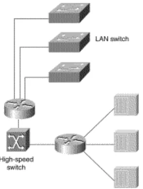
networking applications. LAN switches provide this performance benefit by increasing bandwidth and throughput for workgroups and local servers. Network designers are deploying LAN switches out toward the network's edge in wiring closets. As Figure 1-3 shows, these switches are usually installed to replace shared concentrator hubs and give higher bandwidth connections to the end user.
Figure 1-3: Example of trends in campus design.
Layer 3 networking is required in the network to interconnect the switched workgroups and to provide services that include security, quality of service (QoS), and traffic management. Routing integrates these switched networks, and provides the security, stability, and control needed to build functional and
scalable networks.
Traditionally, Layer 2 switching has been provided by LAN switches, and Layer 3 networking has been provided by routers. Increasingly, these two networking functions are being integrated into common platforms. For example, multilayer switches that provide Layer 2 and 3 functionality are now appearing in the marketplace.
With the advent of such technologies as Layer 3 switching, LAN switching, and virtual LANs (VLANs), building campus networks is becoming more complex than in the past. Table 1-1 summarizes the various LAN technologies that are required to build successful campus networks. Cisco Systems offers product solutions in all of these technologies.
Table 1-1: Summary of LAN Technologies
LAN Technology Typical Uses
Routing technologies Routing is a key technology for connecting LANs in a campus network. It can be either Layer 3 switching or more traditional routing with Layer 3 switching and additional router features.
Introduction
Gigabit Ethernet Gigabit Ethernet builds on top of the Ethernet protocol, but increases speed ten-fold over Fast Ethernet to 1000 Mbps, or 1 Gbps. Gigabit Ethernet provides high bandwidth capacity for backbone designs while providing backward compatibility for installed media.
Ethernet switching provides Layer 2 switching, and offers
dedicated Ethernet segments for each connection. This is the base fabric of the network.
Token Ring switching offers the same functionality as Ethernet switching, but uses Token Ring technology. You can use a Token Ring switch as either a transparent bridge or as a source-route bridge.
ATM switching technologies ATM switching offers high-speed switching technology for voice, video, and data. Its operation is similar to LAN switching
technologies for data operations. ATM, however, offers high bandwidth capacity.
Network designers are now designing campus networks by purchasing separate equipment types (for example, routers, Ethernet switches, and ATM switches) and then linking them together. Although individual purchase decisions might seem harmless, network designers must not forget that the entire network forms an internetwork.
It is possible to separate these technologies and build thoughtful designs using each new technology, but network designers must consider the overall integration of the network. If this overall integration is not considered, the result can be networks that have a much higher risk of network outages, downtime, and congestion than ever before.
Designing WANs
WAN communication occurs between geographically separated areas. In enterprise internetworks, WANs connect campuses together. When a local end station wants to communicate with a remote end station (an end station located at a different site), information must be sent over one or more WAN links. Routers within enterprise internetworks represent the LAN/WAN junction points of an internetwork. These routers determine the most appropriate path through the internetwork for the required data streams. WAN links are connected by switches, which are devices that relay information through the WAN and dictate the service provided by the WAN. WAN communication is often called a service because the network provider often charges users for the services provided by the WAN (called tariffs). WAN services are provided through the following three primary switching technologies:
Introduction
Circuit switching
Each switching technique has advantages and disadvantages. For example, circuit-switched networks offer users dedicated bandwidth that cannot be infringed upon by other users. In contrast,
packet-switched networks have traditionally offered more flexibility and used network bandwidth more efficiently than circuit-switched networks. Cell switching, however, combines some aspects of circuit and packet switching to produce networks with low latency and high throughput. Cell switching is rapidly gaining in popularity. ATM is currently the most prominent cell-switched technology. For more information on switching technology for WANs and LANs, see "Internetworking Design Basics."
Trends in WAN Design
Traditionally, WAN communication has been characterized by relatively low throughput, high delay, and high error rates. WAN connections are mostly characterized by the cost of renting media (wire) from a service provider to connect two or more campuses together. Because the WAN infrastructure is often rented from a service provider, WAN network designs must optimize the cost of bandwidth and
bandwidth efficiency. For example, all technologies and features used to connect campuses over a WAN are developed to meet the following design requirements:
Optimize WAN bandwidth ●
Minimize the tariff cost ●
Maximize the effective service to the end users ●
Recently, traditional shared-media networks are being overtaxed because of the following new network requirements:
Necessity to connect to remote sites ●
Growing need for users to have remote access to their networks ●
Explosive growth of the corporate intranets ●
Increased use of enterprise servers ●
Network designers are turning to WAN technology to support these new requirements. WAN
connections generally handle mission-critical information, and are optimized for price/performance bandwidth. The routers connecting the campuses, for example, generally apply traffic optimization, multiple paths for redundancy, dial backup for disaster recovery, and QoS for critical applications.
Table 1-2 summarizes the various WAN technologies that support such large-scale internetwork requirements.
Table 1-2: Summary of WAN Technologies
WAN Technology Typical Uses
Introduction
Asymmetric Digital Subscriber Line A new modem technology. Converts existing twisted-pair telephone lines into access paths for multimedia and high-speed data communica- tions. ADSL transmits more than 6 Mbps to a subscriber, and as much as 640 kbps more in both directions.
Analog modem Analog modems can be used by telecommuters and
mobile users who access the network less than two hours per day, or for backup for another type of link.
Leased line Leased lines can be used for Point-to-Point Protocol
(PPP) networks and hub-and-spoke topologies, or for backup for another type of link.
Integrated Services Digital Network (ISDN)
ISDN can be used for cost-effective remote access to corporate networks. It provides support for voice and video as well as a backup for another type of link.
Frame Relay Frame Relay provides a cost-effective, high- speed,
low-latency mesh topology between remote sites. It can be used in both private and carrier-provided networks.
Switched Multimegabit Data Service (SMDS)
SMDS provides high-speed, high-performance
connections across public data networks. It can also be deployed in metropolitan-area networks (MANs).
X.25 X.25 can provide a reliable WAN circuit or backbone.
It also provides support for legacy applications.
WAN ATM WAN ATM can be used to accelerate bandwidth
requirements. It also provides support for multiple QoS classes for differing application requirements for delay and loss.
Introduction
Utilizing Remote Connection Design
Remote connections link single users (mobile users and/or telecommuters) and branch offices to a local campus or the Internet. Typically, a remote site is a small site that has few users and therefore needs a smaller size WAN connection. The remote requirements of an internetwork, however, usually involve a large number of remote single users or sites, which causes the aggregate WAN charge to be exaggerated. Because there are so many remote single users or sites, the aggregate WAN bandwidth cost is
proportionally more important in remote connections than in WAN connections. Given that the three-year cost of a network is nonequipment expenses, the WAN media rental charge from a service provider is the largest cost component of a remote network. Unlike WAN connections, smaller sites or single users seldom need to connect 24 hours a day.
Consequently, network designers typically choose between dial-up and dedicated WAN options for remote connections. Remote connections generally run at speeds of 128 Kbps or lower. A network designer might also employ bridges in a remote site for their ease of implementation, simple topology, and low traffic requirements.
Trends in Remote Connections
Today, there is a large selection of remote WAN media that include the following: Analog modem
Remote connections also optimize for the appropriate WAN option to provide cost-effective bandwidth, minimize dial-up tariff costs, and maximize effective service to users.
Trends in LAN/WAN Integration
Today, 90 percent of computing power resides on desktops, and that power is growing exponentially. Distributed applications are increasingly bandwidth hungry, and the emergence of the Internet is driving many LAN architectures to the limit. Voice communications have increased significantly with more reliance on centralized voice mail systems for verbal communications. The internetwork is the critical tool for information flow. Internetworks are being pressured to cost less, yet support the emerging applications and higher number of users with increased performance.
To date, local- and wide-area communications have remained logically separate. In the LAN, bandwidth is free and connectivity is limited only by hardware and implementation costs. The LAN has carried data only. In the WAN, bandwidth has been the overriding cost, and such delay-sensitive traffic as voice has remained separate from data. New applications and the economics of supporting them, however, are forcing these conventions to change.
Introduction
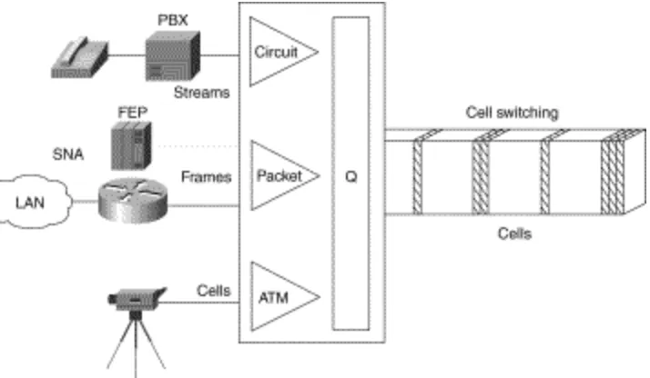
The Internet is the first source of multimedia to the desktop, and immediately breaks the rules. Such Internet applications as voice and real-time video require better, more predictable LAN and WAN performance. These multimedia applications are fast becoming an essential part of the business productivity toolkit. As companies begin to consider implementing new intranet-based, bandwidth-intensive multimedia applications---such as video training, videoconferencing, and voice over IP---the impact of these applications on the existing networking infrastructure is a serious concern. If a company has relied on its corporate network for business-critical SNA traffic, for example, and wants to bring a new video training application on line, the network must be able to provide guaranteed quality of service (QoS) that delivers the multimedia traffic, but does not allow it to interfere with the business-critical traffic. ATM has emerged as one of the technologies for integrating LANs and WANs. The Quality of Service (QoS) features of ATM can support any traffic type in separate or mixed streams, delay sensitive traffic, and nondelay-sensitive traffic, as shown in Figure 1-4.
ATM can also scale from low to high speeds. It has been adopted by all the industry's equipment vendors, from LAN to private branch exchange (PBX).
Figure 1-4: ATM support of various traffic types.
Providing Integrated Solutions
The trend in internetworking is to provide network designers greater flexibility in solving multiple
internetworking problems without creating multiple networks or writing off existing data communication investments. Routers might be relied upon to provide a reliable, secure network and act as a barrier
against inadvertent broadcast storms in the local networks. Switches, which can be divided into two main categories---LAN switches and WAN switches---can be deployed at the workgroup, campus backbone, or WAN level. Remote sites might use low-end routers for connection to the WAN.
Underlying and integrating all Cisco products is the Cisco Internetworking Operating System (Cisco IOS) software. The Cisco IOS software enables disparate groups, diverse devices, and multiple protocols all to be integrated into a highly reliable and scalable network. Cisco IOS software also supports this
Introduction
internetwork with advanced security, quality of service, and traffic services.
Determining Your Internetworking Requirements
Designing an internetwork can be a challenging task. Your first step is to understand your
internetworking requirements. The rest of this chapter is intended as a guide for helping you determine these requirements. After you have identified these requirements, refer to "Internetworking Design Basics," for information on selecting internetwork capability and reliability options that meet these requirements.
Internetworking devices must reflect the goals, characteristics, and policies of the organizations in which they operate. Two primary goals drive internetworking design and implementation:
Application availability---Networks carry application information between computers. If the applications are not available to network users, the network is not doing its job.
●
Cost of ownership---Information system (IS) budgets today often run in the millions of dollars. As large organizations increasingly rely on electronic data for managing business activities, the
associated costs of computing resources will continue to rise. ●
A well-designed internetwork can help to balance these objectives. When properly implemented, the network infrastructure can optimize application availability and allow the cost-effective use of existing network resources.
The Design Problem: Optimizing Availability and Cost
In general, the network design problem consists of the following three general elements:
Environmental givens---Environmental givens include the location of hosts, servers, terminals, and other end nodes; the projected traffic for the environment; and the projected costs for delivering different service levels.
●
Performance constraints---Performance constraints consist of network reliability, traffic
throughput, and host/client computer speeds (for example, network interface cards and hard drive access speeds).
●
Internetworking variables---Internetworking variables include the network topology, line capacities, and packet flow assignments.
●
The goal is to minimize cost based on these elements while delivering service that does not compromise established availability requirements. You face two primary concerns: availability and cost. These issues are essentially at odds. Any increase in availability must generally be reflected as an increase in cost. As a result, you must weigh the relative importance of resource availability and overall cost carefully. As Figure 1-5 shows, designing your network is an iterative activity. The discussions that follow outline several areas that you should carefully consider when planning your internetworking implementation. Figure 1-5: General network design process.
Introduction
Assessing User Requirements
In general, users primarily want application availability in their networks. The chief components of application availability are response time, throughput, and reliability:
Response time is the time between entry of a command or keystroke and the host system's execution of the command or delivery of a response. User satisfaction about response time is generally considered to be a monotonic function up to some limit, at which point user satisfaction falls off to nearly zero. Applications in which fast response time is considered critical include interactive online services, such as automated tellers and point-of-sale machines.
●
Applications that put high-volume traffic onto the network have more effect on throughput than end-to-end connections. Throughput-intensive applications generally involve file- transfer activities. However, throughput-intensive applications also usually have low response-time
requirements. Indeed, they can often be scheduled at times when response-time-sensitive traffic is low (for example, after normal work hours).
●
Although reliability is always important, some applications have genuine requirements that exceed typical needs. Organizations that require nearly 100 percent up time conduct all activities online or over the telephone. Financial services, securities exchanges, and emergency/police/military
operations are a few examples. These situations imply a requirement for a high level of hardware and topological redundancy. Determining the cost of any downtime is essential in determining the relative importance of reliability to your internetwork.
●
You can assess user requirements in a number of ways. The more involved your users are in the process, the more likely that your evaluation will be accurate. In general, you can use the following methods to obtain this information:
User community profiles---Outline what different user groups require. This is the first step in determining internetwork requirements. Although many users have roughly the same requirements of an electronic mail system, engineering groups using XWindows terminals and Sun workstations ●
Introduction
in an NFS environment have different needs from PC users sharing print servers in a finance department.
Interviews, focus groups, and surveys---Build a baseline for implementing an internetwork.
Understand that some groups might require access to common servers. Others might want to allow external access to specific internal computing resources. Certain organizations might require IS support systems to be managed in a particular way according to some external standard. The least formal method of obtaining information is to conduct interviews with key user groups. Focus groups can also be used to gather information and generate discussion among different
organizations with similar (or dissimilar) interests. Finally, formal surveys can be used to get a statistically valid reading of user sentiment regarding a particular service level or proposed internetworking architecture.
●
Human factors tests---The most expensive, time-consuming, and possibly revealing method is to conduct a test involving representative users in a lab environment. This is most applicable when evaluating response time requirements. As an example, you might set up working systems and have users perform normal remote host activities from the lab network. By evaluating user
reactions to variations in host responsiveness, you can create benchmark thresholds for acceptable performance.
●
Assessing Proprietary and Nonproprietary Solutions
Compatibility, conformance, and interoperability are related to the problem of balancing proprietary functionality and open internetworking flexibility. As a network designer, you might be forced to choose between implementing a multivendor environment and implementing a specific, proprietary capability. For example, the Interior Gateway Routing Protocol (IGRP) provides many useful capabilities, such as a number of features that are designed to enhance its stability. These include hold-downs, split horizons, and poison reverse updates.
The negative side is that IGRP is a proprietary routing protocol. In contrast, the integrated Intermediate System-to Intermediate System (IS-IS) protocol is an open internetworking alternative that also provides a fast converging routing environment; however, implementing an open routing protocol can potentially result in greater multiple-vendor configuration complexity.
The decisions that you make have far-ranging effects on your overall internetwork design. Assume that you decide to implement integrated IS-IS instead of IGRP. In doing this, you gain a measure of
interoperability; however, you lose some functionality. For instance, you cannot load balance traffic over unequal parallel paths. Similarly, some modems provide a high level of proprietary diagnostic
capabilities, but require that all modems throughout a network be of the same vendor type to fully exploit proprietary diagnostics.
Previous internetworking (and networking) investments and expectations for future requirements have considerable influence over your choice of implementations. You need to consider installed
internetworking and networking equipment; applications running (or to be run) on the network; traffic patterns; physical location of sites, hosts, and users; rate of growth of the user community; and both physical and logical network layout.
Assessing Costs
Introduction
The internetwork is a strategic element in your overall information system design. As such, the cost of your internetwork is much more than the sum of your equipment purchase orders. View it as a total cost-of-ownership issue. You must consider the entire life cycle of your internetworking environment. A brief list of costs associated with internetworks follows:
Equipment hardware and software costs---Consider what is really being bought when you purchase your systems; costs should include initial purchase and installation, maintenance, and projected upgrade costs.
●
Performance tradeoff costs---Consider the cost of going from a five-second response time to a half-second response time. Such improvements can cost quite a bit in terms of media selection, network interfaces, internetworking nodes, modems, and WAN services.
●
Installation costs---Installing a site's physical cable plant can be the most expensive element of a large network. The costs include installation labor, site modification, fees associated with local code conformance, and costs incurred to ensure compliance with environmental restrictions (such as asbestos removal). Other important elements in keeping your costs to a minimum will include developing a well-planned wiring closet layout and implementing color code conventions for cable runs.
●
Expansion costs---Calculate the cost of ripping out all thick Ethernet, adding additional
functionality, or moving to a new location. Projecting your future requirements and accounting for future needs saves time and money.
●
Support costs---Complicated internetworks cost more to monitor, configure, and maintain. Your internetwork should be no more complicated than necessary. Costs include training, direct labor (network managers and administrators), sparing, and replacement costs. Additional cost that should be included is out-of-band management, SNMP management stations, and power. ●
Cost of downtime---Evaluate the cost for every minute that a user is unable to access a file server or a centralized database. If this cost is high, you must attribute a high cost to downtime. If the cost is high enough, fully redundant internetworks might be your best option.
●
Opportunity costs---Every choice you make has an opposing alternative option. Whether that option is a specific hardware platform, topology solution, level of redundancy, or system
integration alternative, there are always options. Opportunity costs are the costs of not picking one of those options. The opportunity costs of not switching to newer technologies and topologies might be lost competitive advantage, lower productivity, and slower overall performance. Any effort to integrate opportunity costs into your analysis can help to make accurate comparisons at the beginning of your project.
●
Sunken costs---Your investment in existing cable plant, routers, concentrators, switches, hosts, and other equipment and software are your sunken costs. If the sunken cost is high, you might need to modify your networks so that your existing internetwork can continue to be utilized. Although comparatively low incremental costs might appear to be more attractive than significant redesign costs, your organization might pay more in the long run by not upgrading systems. Over reliance on sunken costs can cost your organization sales and market share when calculating the cost of internetwork modifications and additions.
●
Estimating Traffic: Work Load Modeling
Empirical work-load modeling consists of instrumenting a working internetwork and monitoring traffic
Introduction
for a given number of users, applications, and network topology. Try to characterize activity throughout a normal work day in terms of the type of traffic passed, level of traffic, response time of hosts, time to execute file transfers, and so on. You can also observe utilization on existing network equipment over the test period.
If the tested internetwork's characteristics are close to the new internetwork, you can try extrapolating to the new internetwork's number of users, applications, and topology. This is a best-guess approach to traffic estimation given the unavailability of tools to characterize detailed traffic behavior.
In addition to passive monitoring of an existing network, you can measure activity and traffic generated by a known number of users attached to a representative test network and then extrapolate findings to your anticipated population.
One problem with modeling workloads on networks is that it is difficult to accurately pinpoint traffic load and network device performance as functions of the number of users, type of application, and geographical location. This is especially true without a real network in place. Consider the following factors that influence the dynamics of the network:
The time-dependent nature of network access---Peak periods can vary; measurements must reflect a range of observations that includes peak demand.
●
Differences associated with type of traffic---Routed and bridged traffic place different demands on internetwork devices and protocols; some protocols are sensitive to dropped packets; some
application types require more bandwidth. ●
The random (nondeterministic) nature of network traffic---Exact arrival time and specific effects of traffic are unpredictable.
●
Sensitivity Testing
From a practical point of view, sensitivity testing involves breaking stable links and observing what happens. When working with a test network, this is relatively easy. Disturb the network by removing an active interface, and monitor how the change is handled by the internetwork: how traffic is rerouted, the speed of convergence, whether any connectivity is lost, and whether problems arise in handling specific types of traffic. You can also change the level of traffic on a network to determine the effects on the network when traffic levels approach media saturation. This empirical testing is a type of regression testing: A series of specific modifications (tests) are repeated on different versions of network
configurations. By monitoring the effects on the design variations, you can characterize the relative resilience of the design.
Note Modeling sensitivity tests using a computer is beyond the scope of this publication. A useful source for more information about computer-based network design and simulation is A.S. Tannenbaum,
Computer Networks, Upper Saddle River, New Jersey: Prentice Hall, 1996.
Introduction
Summary
After you have determined your network requirements, you must identify and then select the specific capability that fits your computing environment. For basic information on the different types of
internetworking devices along with a description of a hierarchical approach to internetworking, refer to
"Internetworking Design Basics."
Chapters 2-13 in this book are technology chapters that present detailed discussions about specific implementations of large-scale internetworks in the following environments:
Large-scale Internetwork Protocol (IP) internetworks
Enhanced Interior Gateway Routing Protocol (IGRP) design ❍
Open Shortest Path First (OSPF) design ❍
●
IBM System Network Architecture (SNA) internetworks Source-route bridging (SRB) design
❍
Synchronous Data Link Control (SDLC) and serial tunneling (STUN), SDLC Logical Link Control type 2 (SDLLC), and Qualified Logical Link Control (QLLC) design
❍
Advanced Peer-to-Peer Networking (APPN) and Data Link Switching (DLSw) design ❍
In addition to these technology chapters there are chapters on designing switched LAN internetworks, campus LANs, and internetworks for multimedia applications. Case studies for the information contained in this book are contained in the Internetworking Case Studies.
Posted: Fri Oct 29 11:08:11 PDT 1999
Copyright 1989-1999©Cisco Systems Inc.
Introduction
Table of Contents
Internetworking Design Basics
Understanding Basic Internetworking Concepts Overview of Internetworking Devices Switching Overview
Layer 2 and Layer 3 Switching
Identifying and Selecting Internetworking Capabilities Identifying and Selecting an Internetworking Model Using the Hierarchical Design Model
Function of the Core Layer Function of the Distribution Layer Function of the Access Layer Evaluating Backbone Services
Naming, Proxy, and Local Cache Capabilities Media Access Security
Router Discovery
Choosing Internetworking Reliability Options Redundant Links Versus Meshed Topologies Redundant Power Systems
Fault-Tolerant Media Implementations Backup Hardware
Identifying and Selecting Internetworking Devices Benefits of Switches (Layer 2 Services)
Internetworking Design Basics
Benefits of Routers (Layer 3 Services) Backbone Routing Options Types of Switches
LAN Switches ATM Switches
Workgroup and Campus ATM Switches Enterprise ATM Switches
Multiservice Access Switches Switches and Routers Compared
Role of Switches and Routers in VLANs
Examples of Campus Switched Internetwork Designs Summary
Internetworking Design Basics
Designing an internetwork can be a challenging task. An internetwork that consists of only 50 meshed routing nodes can pose complex problems that lead to unpredictable results. Attempting to optimize internetworks that feature thousands of nodes can pose even more complex problems.
Despite improvements in equipment performance and media capabilities, internetwork design is becoming more difficult. The trend is toward increasingly complex environments involving multiple media, multiple protocols, and interconnection to networks outside any single organization's dominion of control. Carefully designing internetworks can reduce the hardships associated with growth as a networking environment evolves.
This chapter provides an overview of planning and design guidelines. Discussions are divided into the following general topics:
Understanding Basic Internetworking Concepts ●
Identifying and Selecting Internetworking Capabilities ●
Identifying and Selecting Internetworking Devices ●
Understanding Basic Internetworking Concepts
This section covers the following basic internetworking concepts: Overview of Internetworking Devices
●
Switching Overview ●
Overview of Internetworking Devices
Network designers faced with designing an internetwork have four basic types of internetworking devices available to them: Hubs (concentrators)
Table 2-1 summarizes these four internetworking devices.
Table 2-1: Summary of Internetworking Devices
Internetworking Design Basics
Device Description
Hubs (concentrators) Hubs (concentrators) are used to connect multiple users to a single physical device, which connects to the network. Hubs and concentrators act as repeaters by regenerating the signal as it passes through them.
Bridges Bridges are used to logically separate network segments within the same network. They operate at the OSI data link layer (Layer 2) and are independent of higher-layer protocols.
Switches Switches are similar to bridges but usually have more ports. Switches provide a unique network segment on each port, thereby separating collision domains. Today, network designers are replacing hubs in their wiring closets with switches to increase their network performance and bandwidth while protecting their existing wiring investments.
Routers Routers separate broadcast domains and are used to connect different networks. Routers direct network traffic based on the destination network layer address (Layer 3) rather than the workstation data link layer or MAC address. Routers are protocol dependent.
Data communications experts generally agree that network designers are moving away from bridges and concentrators and primarily using switches and routers to build internetworks. Consequently, this chapter focuses primarily on the role of switches and routers in internetwork design.
Switching Overview
Today in data communications, all switching and routing equipment perform two basic operations:
Switching data frames---This is generally a store-and-forward operation in which a frame arrives on an input media and is transmitted to an output media.
●
Maintenance of switching operations---In this operation, switches build and maintain switching tables and search for loops. Routers build and maintain both routing tables and service tables.
●
There are two methods of switching data frames: Layer 2 and Layer 3 switching.
Layer 2 and Layer 3 Switching
Switching is the process of taking an incoming frame from one interface and delivering it out through another interface. Routers use Layer 3 switching to route a packet, and switches (Layer 2 switches) use Layer 2 switching to forward frames.
The difference between Layer 2 and Layer 3 switching is the type of information inside the frame that is used to determine the correct output interface. With Layer 2 switching, frames are switched based on MAC address information. With Layer 3 switching, frames are switched based on network-layer information.
Layer 2 switching does not look inside a packet for network-layer information as does Layer 3 switching. Layer 2 switching is performed by looking at a destination MAC address within a frame. It looks at the frame's destination address and sends it to the appropriate interface if it knows the destination address location. Layer 2 switching builds and maintains a switching table that keeps track of which MAC addresses belong to each port or interface.
If the Layer 2 switch does not know where to send the frame, it broadcasts the frame out all its ports to the network to learn the correct destination. When the frame's reply is returned, the switch learns the location of the new address and adds the
information to the switching table.
Layer 2 addresses are determined by the manufacturer of the data communications equipment used. They are unique addresses that are derived in two parts: the manufacturing (MFG) code and the unique identifier. The MFG code is assigned to each
Internetworking Design Basics
vendor by the IEEE. The vendor assigns a unique identifier to each board it produces. Except for Systems Network
Architecture (SNA) networks, users have little or no control over Layer 2 addressing because Layer 2 addresses are fixed with a device, whereas Layer 3 addresses can be changed. In addition, Layer 2 addresses assume a flat address space with
universally unique addresses.
Layer 3 switching operates at the network layer. It examines packet information and forwards packets based on their network-layer destination addresses. Layer 3 switching also supports router functionality.
For the most part, Layer 3 addresses are determined by the network administrator who installs a hierarchy on the network. Protocols such as IP, IPX, and AppleTalk use Layer 3 addressing. By creating Layer 3 addresses, a network administrator creates local areas that act as single addressing units (similar to streets, cities, states, and countries), and assigns a number to each local entity. If users move to another building, their end stations will obtain new Layer 3 addresses, but their Layer 2 addresses remain the same.
As routers operate at Layer 3 of the OSI model, they can adhere to and formulate a hierarchical addressing structure. Therefore, a routed network can tie a logical addressing structure to a physical infrastructure, for example, through TCP/IP subnets or IPX networks for each segment. Traffic flow in a switched (flat) network is therefore inherently different from traffic flow in a routed (hierarchical) network. Hierarchical networks offer more flexible traffic flow than flat networks because they can use the network hierarchy to determine optimal paths and contain broadcast domains.
Implications of Layer 2 and Layer 3 Switching
The increasing power of desktop processors and the requirements of client-server and multimedia applications have driven the need for greater bandwidth in traditional shared-media environments. These requirements are prompting network designers to replace hubs in wiring closets with switches.
Although Layer 2 switches use microsegmentation to satisfy the demands for more bandwidth and increased performance, network designers are now faced with increasing demands for intersubnet communication. For example, every time a user accesses servers and other resources, which are located on different subnets, the traffic must go through a Layer 3 device. Figure 2-1 shows the route of intersubnet traffic with Layer 2 switches and Layer 3 switches.
Figure 2-1: Flow of intersubnet traffic with Layer 2 switches and routers.
As Figure 2-1 shows, for Client X to communicate with Server Y, which is on another subnet, it must traverse through the following route: first through Switch A (a Layer 2 switch) and then through Router A (a Layer 3 switch) and finally through Switch B (a Layer 2 switch). Potentially there is a tremendous bottleneck, which can threaten network performance, because the intersubnet traffic must pass from one network to another.
To relieve this bottleneck, network designers can add Layer 3 capabilities throughout the network. They are implementing Layer 3 switching on edge devices to alleviate the burden on centralized routers. Figure 2-2 illustrates how deploying Layer 3 switching throughout the network allows Client X to directly communicate with Server Y without passing through Router A.
Figure 2-2: Flow of intersubnet traffic with Layer 3 switches.
Internetworking Design Basics
Identifying and Selecting Internetworking Capabilities
After you understand your internetworking requirements, you must identify and then select the specific capabilities that fit your computing environment. The following discussions provide a starting point for making these decisions:
Identifying and Selecting an Internetworking Model ●
Choosing Internetworking Reliability Options ●
Identifying and Selecting an Internetworking Model
Hierarchical models for internetwork design allow you to design internetworks in layers. To understand the importance of layering, consider the Open System Interconnection (OSI) reference model, which is a layered model for understanding and implementing computer communications. By using layers, the OSI model simplifies the task required for two computers to communicate. Hierarchical models for internetwork design also uses layers to simplify the task required for internetworking. Each layer can be focused on specific functions, thereby allowing the networking designer to choose the right systems and features for the layer.
Using a hierarchical design can facilitate changes. Modularity in network design allows you to create design elements that can be replicated as the network grows. As each element in the network design requires change, the cost and complexity of making the upgrade is constrained to a small subset of the overall network. In large flat or meshed network architectures, changes tend to impact a large number of systems. Improved fault isolation is also facilitated by modular structuring of the network into small, easy-to-understand elements. Network mangers can easily understand the transition points in the network, which helps identify failure points.
Using the Hierarchical Design Model
A hierarchical network design includes the following three layers:
The backbone (core) layer that provides optimal transport between sites ●
The distribution layer that provides policy-based connectivity ●
The local-access layer that provides workgroup/user access to the network ●
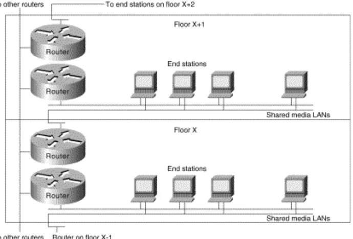
Figure 2-3 shows a high-level view of the various aspects of a hierarchical network design. A hierarchical network design presents three layers---core, distribution, and access---with each layer providing different functionality.
Figure 2-3: Hierarchical network design model.
Internetworking Design Basics
Function of the Core Layer
The core layer is a high-speed switching backbone and should be designed to switch packets as fast as possible. This layer of the network should not perform any packet manipulation, such as access lists and filtering, that would slow down the switching of packets.
Function of the Distribution Layer
The distribution layer of the network is the demarcation point between the access and core layers and helps to define and differentiate the core. The purpose of this layer is to provide boundary definition and is the place at which packet manipulation can take place. In the campus environment, the distribution layer can include several functions, such as the following:
Address or area aggregation
Any media transitions that need to occur ●
Security ●
In the non-campus environment, the distribution layer can be a redistribution point between routing domains or the
demarcation between static and dynamic routing protocols. It can also be the point at which remote sites access the corporate network. The distribution layer can be summarized as the layer that provides policy-based connectivity.
Function of the Access Layer
The access layer is the point at which local end users are allowed into the network. This layer may also use access lists or filters to further optimize the needs of a particular set of users. In the campus environment, access-layer functions can include the following:
In the non-campus environment, the access layer can give remote sites access to the corporate network via some wide-area technology, such as Frame Relay, ISDN, or leased lines.
It is sometimes mistakenly thought that the three layers (core, distribution, and access) must exist in clear and distinct physical entities, but this does not have to be the case. The layers are defined to aid successful network design and to represent
functionality that must exist in a network. The instantiation of each layer can be in distinct routers or switches, can be represented by a physical media, can be combined in a single device, or can be omitted altogether. The way the layers are implemented depends on the needs of the network being designed. Note, however, that for a network to function optimally, hierarchy must be maintained.
The discussions that follow outline the capabilities and services associated with backbone, distribution, and local access
Internetworking Design Basics
internetworking services.
Evaluating Backbone Services
This section addresses internetworking features that support backbone services. The following topics are discussed: Path Optimization
One of the primary advantages of a router is its capability to help you implement a logical environment in which optimal paths for traffic are automatically selected. Routers rely on routing protocols that are associated with the various network layer protocols to accomplish this automated path optimization.
Depending on the network protocols implemented, routers permit you to implement routing environments that suit your
specific requirements. For example, in an IP internetwork, Cisco routers can support all widely implemented routing protocols, including Open Shortest Path First (OSPF), RIP, IGRP, Border Gateway Protocol (BGP), Exterior Gateway Protocol (EGP), and HELLO. Key built-in capabilities that promote path optimization include rapid and controllable route convergence and tunable routing metrics and timers.
Convergence is the process of agreement, by all routers, on optimal routes. When a network event causes routes to either halt operation or become available, routers distribute routing update messages. Routing update messages permeate networks, stimulating recalculation of optimal routes and eventually causing all routers to agree on these routes. Routing algorithms that converge slowly can cause routing loops or network outages.
Many different metrics are used in routing algorithms. Some sophisticated routing algorithms base route selection on a
combination of multiple metrics, resulting in the calculation of a single hybrid metric. IGRP uses one of the most sophisticated distance vector routing algorithms. It combines values for bandwidth, load, and delay to create a composite metric value. Link state routing protocols, such as OSPF and IS-IS, employ a metric that represents the cost associated with a given path.
Traffic Prioritization
Although some network protocols can prioritize internal homogeneous traffic, the router prioritizes the heterogeneous traffic flows. Such traffic prioritization enables policy-based routing and ensures that protocols carrying mission-critical data take precedence over less important traffic.
Priority Queuing
Priority queuing allows the network administrator to prioritize traffic. Traffic can be classified according to various criteria, including protocol and subprotocol type, and then queued on one of four output queues (high, medium, normal, or low
priority). For IP traffic, additional fine-tuning is possible. Priority queuing is most useful on low-speed serial links. Figure 2-4 shows how priority queuing can be used to segregate traffic by priority level, speeding the transit of certain packets through the network.
Figure 2-4: Priority queuing.
Internetworking Design Basics
You can also use intraprotocol traffic prioritization techniques to enhance internetwork performance. IP's type-of-service (TOS) feature and prioritization of IBM logical units (LUs) are intraprotocol prioritization techniques that can be implemented to improve traffic handling over routers. Figure 2-5 illustrates LU prioritization.
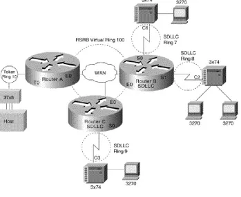
Figure 2-5: LU prioritization implementation.
In Figure 2-5, the IBM mainframe is channel-attached to a 3745 communications controller, which is connected to a 3174 cluster controller via remote source-route bridging (RSRB). Multiple 3270 terminals and printers, each with a unique local LU address, are attached to the 3174. By applying LU address prioritization, you can assign a priority to each LU associated with a terminal or printer; that is, certain users can have terminals that have better response time than others, and printers can have lowest priority. This function increases application availability for those users running extremely important applications.
Finally, most routed protocols (such as AppleTalk, IPX, and DECnet) employ a cost-based routing protocol to assess the relative merit of the different routes to a destination. By tuning associated parameters, you can force particular kinds of traffic to take particular routes, thereby performing a type of manual traffic prioritization.
Custom Queuing
Priority queuing introduces a fairness problem in that packets classified to lower priority queues might not get serviced in a timely manner, or at all. Custom queuing is designed to address this problem. Custom queuing allows more granularity than priority queuing. In fact, this feature is commonly used in the internetworking environment in which multiple higher-layer protocols are supported. Custom queuing reserves bandwidth for a specific protocol, thus allowing mission- critical traffic to receive a guaranteed minimum amount of bandwidth at any time.
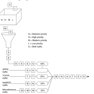
The intent is to reserve bandwidth for a particular type of traffic. For example, in Figure 2-6, SNA has 40 percent of the bandwidth reserved using custom queuing, TCP/IP 20 percent, NetBIOS 20 percent, and the remaining protocols 20 percent. The APPN protocol itself has the concept of class of service (COS), which determines the transmission priority for every message. APPN prioritizes the traffic before sending it to the DLC transmission queue.
Figure 2-6: Custom queuing.
Internetworking Design Basics
Custom queuing prioritizes multiprotocol traffic. A maximum of 16 queues can be built with custom queuing. Each queue is serviced sequentially until the number of bytes sent exceeds the configurable byte count or the queue is empty. One important function of custom queuing is that if SNA traffic uses only 20 percent of the link, the remaining 20 percent allocated to SNA can be shared by the other traffic.
Custom queuing is designed for environments that want to ensure a minimum level of service for all protocols. In today's multiprotocol internetwork environment, this important feature allows protocols of different characteristics to share the media.
Weighted Fair Queuing
Weighted fair queuing is a traffic priority management algorithm that uses the time-division multiplexing (TDM) model to divide the available bandwidth among clients that share the same interface. In time-division multiplexing, each client is allocated a time slice in a round-robin fashion. In weighted fair queuing, the bandwidth is distributed evenly among clients so that each client gets a fair share if every one has the same weighting. You can assign a different set of weights, for example through type-of-service, so that more bandwidth is allocated.
If every client is allocated the same bandwidth independent of the arrival rates, the low volume traffic has effective priority over high volume traffic. The use of weighting allows time-delay-sensitive traffic to obtain additional bandwidth, thus consistent response time is guaranteed under heavy traffic. There are different types of data stream converging on a wire, as shown in Figure 2-7.
Figure 2-7: Weighted fair queuing.
Internetworking Design Basics
Both C and E are FTP sessions, and they are high-volume traffic. A, B, and D are interactive sessions and they are low-volume traffic. Every session in this case is termed a conversation. If each conversation is serviced in a cyclic manner and gets a slot regardless of its arrival rate, the FTP sessions do not monopolize the bandwidth. Round trip delays for the interactive traffic, therefore, become predictable.
Weighted fair queuing provides an algorithm to identify data streams dynamically using an interface, and sorts them into separate logical queues. The algorithm uses various discriminators based on whatever network layer protocol information is available and sorts among them. For example, for IP traffic, the discriminators are source and destination address, protocol type, socket numbers, and TOS. This is how the two Telnet sessions (Sessions B and D) are assigned to different logical queues, as shown in Figure 2-7.
Ideally, the algorithm would classify every conversation that is sharing the wire so that each conversation receives its fair share of the bandwidth. Unfortunately, with such protocols as SNA, you cannot distinguish one SNA session from another. For example, in DLSw+, SNA traffic is multiplexed onto a single TCP session. Similarly in APPN, SNA sessions are multiplexed onto a single LLC2 session.
The weighted fair queuing algorithm treats these sessions as a single conversation. If you have many TCP sessions, the TCP sessions get the majority of the bandwidth and the SNA traffic gets the minimum. For this reason, this algorithm is not recommended for SNA using DLSw+ TCP/IP encapsulation and APPN.
Weighted fair queuing, however, has many advantages over priority queuing and custom queuing. Priority queuing and custom queuing require the installation of access lists; the bandwidth has to be pre-allocated and priorities have to be predefined. This is clearly a burden. Sometimes, network administrators cannot identify and prioritize network traffic in real time. Weighted fair queuing sorts among individual traffic streams without the administrative burden associated with the other two types of
queuing.
Load Balancing
The easiest way to add bandwidth in a backbone network is to implement additional links. Routers provide built-in load
balancing for multiple links and paths. You can use up to four paths to a destination network. In some cases, the paths need not be of equal cost.
Within IP, routers provide load balancing on both a per-packet and a per-destination basis. For per-destination load balancing, each router uses its route cache to determine the output interface. If IGRP or Enhanced IGRP routing is used, unequal-cost load balancing is possible. The router uses metrics to determine which paths the packets will take; the amount of load balancing can be adjusted by the user.
Load balancing bridged traffic over serial lines is also supported. Serial lines can be assigned to circuit groups. If one of the serial links in the circuit group is in the spanning tree for a network, any of the serial links in the circuit group can be used for load balancing. Data ordering problems are avoided by assigning each destination to a serial link. Reassignment is done dynamically if interfaces go down or come up.
Alternative Paths
Many internetwork backbones carry mission-critical information. Organizations running such backbones are usually interested in protecting the integrity of this information at virtually any cost. Routers must offer sufficient reliability so that they are not the weak link in the internetwork chain. The key is to provide alternative paths that can come on line whenever link failures occur along active networks.
End-to-end reliability is not ensured simply by making the backbone fault tolerant. If communication on a local segment within any building is disrupted for any reason, that information will not reach the backbone. End-to-end reliability is only possible when redundancy is employed throughout the internetwork. Because this is usually cost prohibitive, most companies prefer to employ redundant paths only on those segments that carry mission-critical information.
What does it take to make the backbone reliable? Routers hold the key to reliable internetworking. Depending on the definition of reliability, this can mean duplicating every major system on each router and possibly every component. However, hardware component duplication is not the entire solution because extra circuitry is necessary to link the duplicate components to allow them to communicate. This solution is usually very expensive, but more importantly, it does not completely address the
Internetworking Design Basics
problem. Even assuming all routers in your network are completely reliable systems, link problems between nodes within a backbone can still defeat a redundant hardware solution.
To really address the problem of network reliability, links must be redundant. Further, it is not enough to simply duplicate all links. Dual links must terminate at multiple routers unless all backbone routers are completely fault tolerant (no single points of failure). Otherwise, backbone routers that are not fault tolerant become single points of failure. The inevitable conclusion is that a completely redundant router is not the most effective solution to the reliability problem because it is expensive and still does not address link reliability.
Most network designers do not implement a completely redundant network. Instead, network designers implement partially redundant internetworks. The section, "Choosing Internetworking Reliability Options," later in this chapter, addresses several hypothetical networks that represent commonly implemented points along the reliability continuum.
Switched Access
Switched access provides the capability to enable a WAN link on an as-needed basis via automated router controls. One model for a reliable backbone consists of dual, dedicated links and one switched link for idle hot backup. Under normal operational conditions, you can load balance over the dual links, but the switched link is not operational until one of the dedicated links fails.
Traditionally, WAN connections over the Public Switched Telephone Network (PSTN) have used dedicated lines. This can be very expensive when an application requires only low-volume, periodic connections. To reduce the need for dedicated circuits, a feature called dial-on-demand routing (DDR) is available. Figure 2-8 illustrates a DDR connection.
Figure 2-8: The Dial-on-demand routing environment.
Using DDR, low-volume, periodic network connections can be made over the PSTN. A router activates the DDR feature when it receives a bridged or routed IP packet destined for a location on the other side of the dial-up line. After the router dials the destination phone number and establishes the connection, packets of any supported protocol can be transmitted. When the transmission is complete, the line is automatically disconnected. By terminating unneeded connections, DDR reduces cost of ownership.
Encapsulation (Tunneling)
Encapsulation takes packets or frames from one network system and places them inside frames from another network system. This method is sometimes called tunneling. Tunneling provides a means for encapsulating packets inside a routable protocol via virtual interfaces. Synchronous Data Link Control (SDLC) transport is also an encapsulation of packets in a routable protocol. In addition, transport provides enhancements to tunneling, such as local data-link layer termination, broadcast avoidance, media conversion, and other scalability optimizations.
Cisco routers support the following encapsulation and tunneling techniques: The IBM technology feature set provides these methods:
Serial tunneling (STUN) or Synchronous Data Link Control (SDLC) Transport ❍
SRB with direct encapsulation ❍
SRB with Fast Sequenced Transport (FST) encapsulation ❍
SRB with Transmission Control Protocol/Internet Protocol (TCP/IP) encapsulation ❍
Data Link Switching Plus (DLSw+) with direct encapsulation ❍
●
Internetworking Design Basics
DLSw+ with TCP/IP encapsulation ❍
DLSw+ with Fast Sequenced Transport/Internet Protocol (FST/IP) encapsulation ❍
DLSw+ with DLSw Lite (Logical Link Control Type 2 [LLC2]) encapsulation ❍
Generic Routing Encapsulation (GRE) ●
Cisco supports encapsulating Novell Internetwork Packet Exchange (IPX), Internet Protocol (IP), Connectionless Network Protocol (CLNP), AppleTalk, DECnet Phase IV, Xerox Network Systems (XNS), Banyan Virtual Network System (VINES), and Apollo packets for transport over IP
Single-protocol tunneling techniques: Cayman (AppleTalk over IP), AURP (AppleTalk over IP), EON (CLNP over IP), and NOS (IP over IP)
●
The following discussion focuses on IBM encapsulations and the multiprotocol GRE tunneling feature.
IBM Features
STUN allows two devices that are normally connected by a direct serial link, using protocols compliant with SDLC or High-level Data Link Control (HDLC), to be connected through one or more routers. The routers can be connected via a multiprotocol network of arbitrary topology. STUN allows integration of System Network Architecture (SNA) networks and non-SNA networks using routers and existing network links. Transport across the multiprotocol network that connects the routers can use TCP/IP. This type of transport offers reliability and intelligent routing via any supported IP routing protocol. A STUN configuration is shown in Figure 2-9.
Figure 2-9: STUN configuration.
SDLC Transport is a variation of STUN that allows sessions using SDLC protocols and TCP/IP encapsulation to be locally terminated. SDLC Transport permits participation in SDLC windowing and retransmission activities.
When connecting remote devices that use SRB over a slow-speed serial link, most network designers choose RSRB with direct HDLC encapsulation. In this case, SRB frames are encapsulated in an HDLC-compliant header. This solution adds little overhead, preserving valuable serial link bandwidth. Direct HDLC encapsulation is not restricted to serial links (it can also be used over Ethernet, Token Ring, and FDDI links), but is most useful in situations in which additional control overhead on the
Internetworking Design Basics
encapsulating network is not tolerable.
When more overhead can be tolerated, frame sequencing is important, but extremely reliable delivery is not needed, and SRB packets can be sent over serial, Token Ring, Ethernet, and FDDI networks using FST encapsulation. FST is similar to TCP in that it provides packet sequencing. However, unlike TCP, FST does not provide packet-delivery acknowledgment.
For extremely reliable delivery in environments in which moderate overhead can be tolerated, you can choose to encapsulate SRB frames in TCP/IP packets. This solution is not only reliable, it can also take advantage of routing features that include handling via routing protocols, packet filtering, and multipath routing.
Generic Routing Encapsulation (GRE)
Cisco's Generic Routing Encapsulation (GRE) multiprotocol carrier protocol encapsulates IP, CLNP, IPX, AppleTalk, DECnet Phase IV, XNS, VINES, and Apollo packets inside IP tunnels. With GRE tunneling, a Cisco router at each site encapsulates protocol-specific packets in an IP header, creating a virtual point-to-point link to Cisco routers at other ends of an IP cloud, where the IP header is stripped off. By connecting multiprotocol subnetworks in a single-protocol backbone environment, IP tunneling allows network expansion across a single-protocol backbone environment. GRE tunneling involves three types of protocols:
Passenger---The protocol is encapsulated (IP, CLNP, IPX, AppleTalk, DECnet Phase IV, XNS, VINES and Apollo). ●
Carrier---GRE protocol provides carrier services. ●
Transport---IP carries the encapsulated protocol. ●
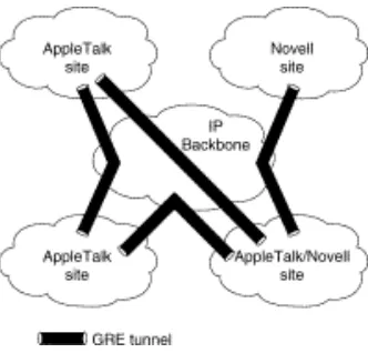
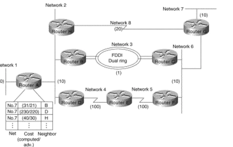
GRE tunneling allows desktop protocols to take advantage of the enhanced route selection capabilities of IP. Many local-area network (LAN) protocols, including AppleTalk and Novell IPX, are optimized for local use. They have limited route selection metrics and hop count limitations. In contrast, IP routing protocols allow more flexible route selection and scale better over large internetworks. Figure 2-10 illustrates GRE tunneling across a single IP backbone between sites. Regardless of how many routers and paths may be associated with the IP cloud, the tunnel is seen as a single hop.
Figure 2-10: Using a single protocol backbone.
GRE provides key capabilities that other encapsulation protocols lack: sequencing and the capability to carry tunneled data at high speeds. Some higher-level protocols require that packets are delivered in correct order. The GRE sequencing option provides this capability. GRE also has an optional key feature that allows you to avoid configuration errors by requiring the same key to be entered at each tunnel endpoint before the tunneled data is processed. IP tunneling also allows network
designers to implement policies, such as which types of traffic can use which routes or assignment of priority or security levels to particular traffic. Capabilities like these are lacking in many native LAN protocols.
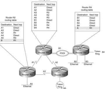
IP tunneling provides communication between subnetworks that have invalid or discontiguous network addresses. With tunneling, virtual network addresses are assigned to subnetworks, making discontiguous subnetworks reachable. Figure 2-11 illustrates that with GRE tunneling, it is possible for the two subnetworks of network 131.108.0.0 to talk to each other even though they are separated by another network.
Internetworking Design Basics