188 Proceedings of the 2013 International Conference on Computer Science and Information Technology (CSIT-2013)
Transformation of PROMELA to Channel
Systems
Sheila Nurul Huda
Jurusan Teknik Informatika, Fakultas Teknologi Industri Universitas Islam Indonesia
Jl. Kaliurang Km. 14 Yogyakarta, Indonesia, 55501 Tel +62274895287 ext.122, Faks. +62274895007 ext.148
Reza Pulungan
Jurusan Ilmu Komputer dan Elektronika, Fakultas Matematika dan Ilmu Pengetahuan Alam, Universitas Gadjah Mada
FMIPA Gedung Selatan, Sekip Unit III Kotak Pos BLS. 21 Yogyakarta, Indonesia, 55281
Tel/Fax +62274546194 [email protected]
Abstract—This paper reports on an implementation of transformation of PROMELA models into Channel Systems, which will be further transformed into Labeled Transition Systems (LTSs). The objective of this transformation is to obtain a formal semantics for further model checking purposes. A Channel System is a way to describe communicating processes that run in parallel, where each process is represented by a Program Graph (PG). The main part of a Program Graph is a location transition which consists of the initial location, a guard which determines whether the transition is executable or not, an action that will be executed in the location transition, and the next location. This paper defined the location transition for PROMELA constructs such as assignments, communication actions, if-fi, do-od, and atomic steps.
Keywords—PROMELA, Channel Systems, Program
Graphs, Model Chesking.
I. INTRODUCTION
PROMELA is a high-level language to describe a model of a system for model checking purpose. Systems that have been modeled in PROMELA can be verified formally using SPIN model checker. Building an abstraction/model of a system is the first key to a successful model checking. With an easy to understand language and ability to model concurrent systems, PROMELA and SPIN have reached an important position in the model-checking world.
System modeled in PROMELA can be verified using SPIN so that the correctness is guaranteed. After it is verified, the modeled system has to be implemented to become a real application. The transformation from PROMELA model to application, all this time, is performed by human by manually programming it in some high-level programming language. This process is proned to errors and mistakes. It is much more convenient and preferable if a verified PROMELA model can be automatically transformed into an application, e.g. application in Java language.
Transformation from modeling language to implementation language is a big endeavour, and has to be done carefully; this process can be viewed in Fig. 1. The transformation itself has to be verified too; which means
that it has to maintain the overall correctness. To achieve the correctness of the transformation, the semantics of the PROMELA model and Java program are needed. We have to make sure that both semantics are equivalent. This can be done by transforming the PROMELA model to a Labeled Transition System (LTS) and, similarly, the Java program to another LTS, then proving that there is an equvalence notion relating both LTSs. LTSs are a universal structure and have a clear semantics. The problem is that a PROMELA model cannot be translated into an LTS as is, because the PROMELA model may contain communication actions among its concurrent processes. One way to transform PROMELA to LTS is via Channel System. Channel System is a formalism that supports communications among concurrent processes via message passing and shared memory. From the resulting Channel System, we can then expand their constituent Program Graphs into an LTS.
189 Proceedings of the 2013 International Conference on Computer Science and Information Technology (CSIT-2013) Fig. 1. Transformation of PROMELA to Java
II. FORMAL DEFINITIONS
A. Program Graph
According to Baier and Katoen [5] Program Graph PG over set Var of typed variables is a tuple (Loc, Act, Effect, ↪, Loc0, g0), where:
Loc is a finite set of location. Act is a set of action.
Effect: Act × Eval(var)
⟶
Eval(var); is the effect function. For example, if α is x=x+y then,Effect(α;; [x=1;y=7])=[x=8;y=7]. Effect describes the result in variable value, which changes when an action α is executed. ↪ ⊆ Loc × Cond(Var) × Act × Loc, is the conditional transition relation. Cond(Var) is a boolean condition defined on the set of variables. If the condition holds true then action α will be executed and then there will be transition to next location.
Loc0⊆ Loc is a set of initial locations.
g0⊆ Cond(Var) is the initial condition.
A.Channel Systems
Baier dan Katoen [5] describes that inside a system, a process will communicate with other processes using channels. Channel System is a way to describe communications among concurrent processes inside a system. A Channel System CS over (Var, Chan) consists of n (data-dependent) process P1 until Pn. Each Pi is a
Program Graph PGi with communication action extension.
We denote a Channel System as:
CS = [P
1|P
2| ...| P
n]
where Pi is a Program Graph over (Var, Chan), where:
Var is a set of variable.
Chan is a set of channels, each (say channel c) with capacity cap(c) and domain dom(c).
So we can denote:
𝑃 = (𝐿𝑜𝑐 , 𝐴𝑐𝑡 , 𝐸𝑓𝑓𝑒𝑐𝑡 , ↪ , 𝐿𝑜𝑐 , 𝑔 ).
A transition in the Channel System is a common conditional transition labeled by guard and action or
labeled with guard and communication action between sending and receiving processes: c!v is sending value v through channel c, and c?x is receiving message through channel c and put the value in variable x.
C. PROMELA
PROMELA is an input language for SPIN model checker. It is used to specify or model a system for model checking purpose. PROMELA is an acronym for Process Meta-Language. The use of the term meta is significant in this context. As we shall see, abstraction is often a key to successful verifications. The specification language is intended to make it easier to find good abstractions for systems designs. PROMELA is not meant to be an implementation language but a systems description language. To make this possible, the emphasis in the language is on the modeling of process synchronization and coordination, and not on computation. The language is also targeted to the description of concurrent software systems, rather than the description of hardware circuits (which is more common for model checking applications) [6].
A PROMELA model P consist of a finite number of processes P1,..., Pn to be executed concurrently. PROMELA supports communications over shared variables and message passing along either synchronous or buffered FIFO-channels. The stepwise behaviour of the processes Pi is specified in PROMELA using a guarded command language [7, 8] with several features of classical imperative programming languages (such as variable assignment, conditional and repetitive commands, sequential composition), communication actions where processes may send and receive messages from the channels, and atomic regions that avoid undesired interleavings. Guarded commands are been used as labels for the edges of Program Graphs and Channel Systems. They consists of a condition (guard) and an action. PROMELA does not use action names, but specifies the effect of actions by statements of the guarded command language [5].
The main ingredients of the statements that formalize the stepwise behaviour of the processes Pi are the atomic commands skip, variable assignment x = expr, communication actions c?x (reading a value for variable x from channel c) and c!expr (sending the current value of an expression over channel c), conditional commands (then-else) and (while) loops. Instead of the standard if-then-else constructs or while-loops, PROMELA supports nondeterministic choices and allows specifying a finite number of guarded commands in conditional and repetitive commands. Syntax of PROMELA statement can be viewed in Fig. 2.
190 Proceedings of the 2013 International Conference on Computer Science and Information Technology (CSIT-2013) III. SEMANTICS OF PROMELA
The operational semantics of a PROMELA statement with variables and channels from (Var, Chan) is given by a Program Graph over (Var, Chan). The Program Graphs PG1, ..., PGn for the processes P1,..., Pn of a PROMELA
model P =[P1| ...|Pn] constitute a Channel Systems over
(Var, Chan) [5].
The Program Graph associated with a PROMELA statement stmt formalizes the control flow when executing stmt. That is, the sub-statements play the role of the locations. For modeling termination, a special location exit is used. The set of sub-statement of PROMELA statement stmt is recursively defined. For statement stmt ∈{skip, x=expr, c?x, c!expr} the set of sub-statements is sub(stmt)={stmt,exit}. For sequential composition let:
𝑠𝑢𝑏(𝑠𝑡𝑚𝑡 ; 𝑠𝑡𝑚𝑡 ) = {𝑠𝑡𝑚𝑡′; 𝑠𝑡𝑚𝑡 𝑠𝑡𝑚𝑡′∈
𝑠𝑢𝑏(𝑠𝑡𝑚𝑡 )\{𝑒𝑥𝑖𝑡}} ∪ 𝑠𝑢𝑏(𝑠𝑡𝑚𝑡 ).
For conditional commands, the set of sub-statements is defined as the set consisting of the if-fi statement itself and sub-statements of its guarded commands. That is, for 𝑖𝑓 ∶ : 𝑔 → 𝑠𝑡𝑚𝑡 … ∷ 𝑔 → 𝑠𝑡𝑚𝑡 𝑓𝑖 we have:
𝑠𝑢𝑏(𝑐𝑜𝑛𝑑_𝑐𝑚𝑑) = {𝑐𝑜𝑛𝑑_𝑐𝑚𝑑 } ∪ ⋃ 𝑠𝑢𝑏(𝑠𝑡𝑚𝑡 ).
The sub-statements of a loop given by 𝑑𝑜 ∶ : 𝑔 → 𝑠𝑡𝑚𝑡 … ∷ 𝑔 → 𝑠𝑡𝑚𝑡 𝑜𝑑 is defined similarly, but taking into account that control moves back to loop when guarded commands terminate. That is:
𝑠𝑢𝑏(𝑙𝑜𝑜𝑝) =
{𝑙𝑜𝑜𝑝, 𝑒𝑥𝑖𝑡} ∪ ⋃ {𝑠𝑡𝑚𝑡′; 𝑙𝑜𝑜𝑝 𝑠𝑡𝑚𝑡′∈
𝑠𝑢𝑏(𝑠𝑡𝑚𝑡 )\ {𝑒𝑥𝑖𝑡}}.
For atomic regions, we let 𝑠𝑢𝑏(𝑎𝑡𝑜𝑚𝑖𝑐{𝑠𝑡𝑚𝑡}) = {𝑎𝑡𝑜𝑚𝑖𝑐{𝑠𝑡𝑚𝑡}, 𝑒𝑥𝑖𝑡}.
Baier and Katoen [5] also provide the inference rules for PROMELA constructs. The inference rules for atomic commands (skip, assignment, communication action) and sequential composition, conditional and repetitive commands give rise to the edges of a large Program Graph where the set of locations agrees with the set of PROMELA statements. Thus, the edges have the form:
where stmt is a PROMELA statement, stmt’ a sub -statement of stmt, and g a guard, α an action, and comm a communication action c?x or c!expr. The subgraph consisting of the sub-statements of Pi then yields the
Program Graph PGi of process Pi as a component of the
program P.
The semantics of the atomic statement skip is given by a single axiom formalizing that the execution of skip terminates in one step without affecting the variables:
where id denotes an action that does not change the values of the variables, i.e., Effect(id, η) = η for all variable evaluations η. Similarly, the execution of a statement consisting of an assignment x = expr has the trivial guard and terminates in one step:
where assign(x, expr) denotes the action that changes the value of x according to the assignment x = expr and does not effect the other variables. For the communication actions c!expr and c?x, the following axioms apply:
The effect of an atomic region atomic{x1 = expr1; ... ;
xm = exprm} is the cumulatve effect of the assignments xi =
expri. It can be defined by the rule:
where α0 = id, αi = Effect(assign(xi, expri), Effect(αi-1,η))
for 1 ≤ i ≤ m.
Sequential composition stmt1; stmt2 is defined by two
rules that distinguish whether or not stmt1 terminates in
one step. If the first step of stmt1 leads to a location
(statement) different from exit, then the following rule applies:
If, however, the computation of stmt1 terminates in one step by executing action α, then control of stmt1;; stmt2 moves to stmt2 after executing α:
The effect of a conditional command 𝑐𝑜𝑛𝑑_𝑐𝑚𝑑 = 𝑖𝑓 ∶ : 𝑔 → 𝑠𝑡𝑚𝑡 … ∷ 𝑔 → 𝑠𝑡𝑚𝑡 𝑓𝑖 is formalized by means of the following rule:
This rule relies on the two step semantics, where the selection of an enabled guarded command and the execution of its first action are split into two steps.
191 Proceedings of the 2013 International Conference on Computer Science and Information Technology (CSIT-2013) If the action is break, then the do-od loop will be
aborted. This is formalized by the following axiom:
IV. DESIGN AND IMPLEMENTATION
The transformator tool has a PROMELA file with .pml extension as an input file. The content of the file has to be recognized so that the transformation can be done to Program Graph. To recognize the content, we need to build lexer and parser. Lexer works to recognize the input file into a token. Then a parser will recognize the meaning (semantics) of a token. In programming, recognizing the words is done via a method call, which represents the structure of the words, so that the sequence of method calls shows the sequence of input words structures [9]. The meaningful token then will be transformed into part of Channel Systems. Parts of the code that will be transformed into Channel System include global variable declaration, proctype declaration, local variable declaration, and statement inside proctype. Java codes are added to recognize variable, change variable object attribute, change Program Graph and state object attribute, and build internal data structures that will be used to generate Channel Systems. Fig. 3 shows the system workflow of the transformation tool.
Fig. 3. The System Workflow of the Transformation Tool
The output of parsing will determine the structures, which part is a variable declaration, which part is a proctype declaration, which part is iterative structure (do-od), which part is conditional command (if-fi), and so on. Along with the recognizion process, after the token is recognized as one of the structures it is then transformed into Channel Systems, by changing proctype into Program Graph and generating the transition locations based on known structures. The transition location is based on formal semantic definition of PROMELA syntax. The recognization and the generation of Channel Systems use depth search first method.
A. Output File Design
The general form of Channel Systems that will be built is as shown in Fig. 4. Channel Systems consist of CS declaration, global variable declaration, active Program Graph declaration, and prototype of all Program Graphs (active and inactive). Inside the prototype of Program Graphs, there may be local variable declaration, and transition locations, which consists of initial location, guard, action, and next location. Atomic structure is wrapped in keyword atomic begin-atomic end. This keyword means to mark that all transition locations inside the keyword is done within a single state transition, which means that no interleaving is allowed.
Fig. 4. Output File Design
B. PROMELA Grammar
PROMELA file is parsed using ANTLR (Another Tool for Language Recognition) [10]. First, the grammar of PROMELA has to be specified. The grammar used in this system is based on PROMELA grammar of Holzmann [11] with proper changes, as shown in Fig. 5 and Fig. 6.
Channel System name_CS over var, chan
...
CS = [PG0 || PG1] Begin
PG0 instance of p() over var, chan ...
Begin
loc_init [guard] [action] loc_next; ...
atomic begin
192 Proceedings of the 2013 International Conference on Computer Science and Information Technology (CSIT-2013) Fig. 5. PROMELA Grammar Part 1
Fig. 6. PROMELA Grammar Part 2
V. RESULT
The PROMELA to Channel Systems transformation tool is made without GUI, because it emphasizes in the transformation process. The result of transformation is validated by comparing the output with the semantics described above.
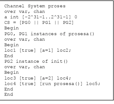
In the following, we briefly give several examples, demonstrating the validation of the transformation. The first one is for declaration of processes in PROMELA as and one instance of init process. Thus, the transformation should show three processes, as depicted in Fig. 8 as the transformation output.
Fig. 8. Transformation Output
Inside the first example, there is assignment a = 2, with trivial guard and it terminates in one step; the output is fitted in with the semantics:
grammar promela; spec : module+ EOF ;
module : proctype | init | mtype | decl_lst; separator : ';' | '-''>' ;
proctype: ('active' ('[' constant ']')?)? 'proctype' name '(' (decl_lst)? ')' '{' sequence * '}';
init: 'init' '{' sequence * '}';
mtype : 'mtype' ('=' )? '{' name ( ',' name )*'}' (';')?;
decl_lst : one_decl (';' one_decl)* (';')? ; one_decl: typeID ivar (',' ivar)*;
typeID: 'boolean' | 'int' | 'mtype' | 'chan' |
receive : varref '?' recv_args;
arg_lst : any_expr ( ',' any_expr ) *;
guard: any_expr | receive | 'else';
binarop: '+' | '-' | '*' | '/' | '>' ('=')? |
constant : 'true' | 'false' | 'skip' | NUMBER;
int a = 0;
PG0, PG1 instances of prosesa() over var, chan
loc4 [true] [run prosesa()] loc5; End
193 Proceedings of the 2013 International Conference on Computer Science and Information Technology (CSIT-2013) Keyword run is considered as an action so it follows
assignment semantics.
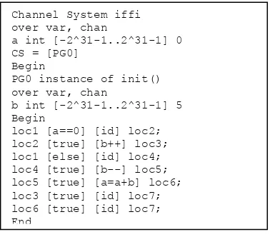
The second example is if-fi construct in PROMELA as shown in Fig. 9.
Fig. 9. if-fi Construct
There are two branches from the if statement, one with the keyword a == 0, other if a is not 0 (else keyword). According to if semantics, we use two step semantics:
When making transition to check the guard, it will execute action id (action without effect), then it will continue with transition for executing command after the guard (i.e. b++ for a == 0 guard, sequential compotition for else guard). Here we can see that the sequential compotition with the computation of first statement terminates in one step, so it must follow the semantics:
The transformation result is depicted in Fig. 10 and it complies with the semantics.
Fig. 10. Transformation Output
For nondeterministic if-fi, the guard will be trivial, all true, so it will not check the guard and terminates in one step (not two step). The third PROMELA example shown in Fig. 11 is nondeterministic if-fi.
Fig. 11. Nondeterministic if-fi
The transformation result will shown two branches from loc1 and there is no guard checking, as shown in Fig. 12.
Fig. 12. Transformation Output
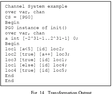
The fourth example is do-od construct as shown in Fig. 13.
Fig. 13. do-od Construct
Execution of a++ will be continued as long as a<5 holds. If not, it will execute break. The loop uses two step semantics, so first it has to check the guard, and then executes the statement after the guard. After executing the statement, it will back to loop. This semantics can be written as:
Break is a keyword for terminating the loop, so when it encounters break, it will go to location exit, as in semantics:
The transformation result complies with the semantics, as shown in Fig. 14.
int a = 0; init{ int b = 5;
if :: a == 0 -> b++;
:: else -> b--; a = a+b; fi
}
Channel System iffi over var, chan
a int [-2^31-1..2^31-1] 0 CS = [PG0]
Begin
PG0 instance of init() over var, chan
b int [-2^31-1..2^31-1] 5 Begin
loc1 [a==0] [id] loc2; loc2 [true] [b++] loc3; loc1 [else] [id] loc4; loc4 [true] [b--] loc5; loc5 [true] [a=a+b] loc6; loc3 [true] [id] loc7; loc6 [true] [id] loc7; End
init { int b; if :: b=0; :: b=1; fi
}
Channel System iffi over var, chan CS = [PG0] Begin
PG0 instance of init() over var, chan
b int [-2^31-1..2^31-1] 0 Begin
loc1 [true] [b=0] loc2; loc1 [true] [b=1] loc3; loc2 [true] [id] loc4; loc3 [true] [id] loc4; End
End
init { int a = 0;
do :: a<5 -> a++; :: else -> break; od
194 Proceedings of the 2013 International Conference on Computer Science and Information Technology (CSIT-2013) Fig. 14. Transformation Output
The validation is also done using other constructs and has shown proper results. More complex examples are also used to make sure all constructs will make a proper composition, such as the Szymanski mutual exclusion protocol [12] is modeled in PROMELA then transformed into Channel Systems. The transformation result shows location transitions comply with the semantics.
VI. CONCLUDING REMARKS
The PROMELA language has been succesfully transformed into Channel Systems. Channel Systems as an operational semantics of PROMELA have a clear semantics and can be implemented as above. All results show that every construct used in the example is transformed well and complied with the semantics. The more complex example is not shown here due to page limitation, but has been checked and gives proper result that follows with the semantics. As the Channel System can be obtained from PROMELA language, the work can continue to form Labeled Transition Systems (LTSs) which is the final structure that is intended to achieve.
REFERENCES
[1] Natarajan, and G. J. Holzmann, “Outline for an Operational-Semantics Definition of Promela,” in Proceedings of the 2nd International Workshop on the SPIN Verification System, DIMACS/Bell Labs/INRS-Telecommunications, 1996.
[2] Weise, “An incremental formal semantics for promela,” in Proceedings of the Third SPIN Workshop, SPIN97, 1997. [3] W. R. Bevier, “Toward an Operational Semantics of PROMELA in
ACL2,” in Proceedings of the Third SPIN Workshop, SPIN97, 1997.
[4] M. del Mar Gallardo, P. Merino, and E. Pimentel, “A Generalized Semantics of PROMELA for Abstract Model Checking,” In Formal Aspect of Computing, 2004.
[5] Baier, and J.-P. Katoen, Principles of Model-Checking, Massachusetts: MIT Press, 2008.
[6] J. Holzmann, The Spin Model Checker, Primer and Reference Manual, Addison Wesley, ISBN 0-321-22862-6, 2003.
[7] W. Dijkstra, A Dicipline of Programming, Prentice-Hall, 1976. [8] R. Apt, and E.–R. Olderog, Verification of Sequential and
Concurrent Programs, Springer-Verlag, 1997.
[9] P. Sestoft, Grammars and Parsing with JAVA, Department of Mathematics and Physics Royal Veterinary and Agricultural University, Denmark, 1999.
[10] T. Parr, The Definitive ANTLR Reference,Texas: The Pragmatic Bookshelf, 2007.
[11] J. Holzmann, SPIN Version6–PROMELA Grammar, http://spinroot.com/spin/Man/grammar.html, May 2012.
[12] K. Szymanski, A Simple Solution to Lamport’s Concurrent Programming Problem with Linear Wait, In Proceedings International Conference on Supercomputing Systems, p. 621-626, 1988.
Channel System example over var, chan
CS = [PG0] Begin
PG0 instance of init() over var, chan
a int [-2^31-1..2^31-1] 0; Begin
loc1 [a<5] [id] loc2; loc2 [true] [a++] loc3; loc3 [true] [id] loc1; loc1 [else] [id] loc4; loc4 [true] [id] loc5; End