Building Wireless Sensor Networks
Building Wireless Sensor Networks by Robert Faludi
Copyright © 2011 Robert Faludi. All rights reserved. Printed in the United States of America.
Published by O’Reilly Media, Inc., 1005 Gravenstein Highway North, Sebastopol, CA 95472.
O’Reilly books may be purchased for educational, business, or sales promotional use. Online editions are also available for most titles (http://my.safaribooksonline.com). For more information, contact our corporate/institutional sales department: 800-998-9938 or [email protected].
Editor: Brian Jepson
Production Editor: Adam Zaremba Copyeditor: Sharon Terdeman
Technical Editors: Kate Hartman and Jordan Husney Proofreader: Sada Preisch
Indexer: Angela Howard
Cover Designer: Karen Montgomery Interior Designer: David Futato Illustrator: Robert Romano
Printing History:
December 2010: First Edition.
Nutshell Handbook, the Nutshell Handbook logo, and the O’Reilly logo are registered trademarks of O’Reilly Media, Inc. Building Wireless Sensor Networks, the image of dachshunds, and related trade dress are trademarks of O’Reilly Media, Inc.
Many of the designations used by manufacturers and sellers to distinguish their products are claimed as trademarks. Where those designations appear in this book, and O’Reilly Media, Inc., was aware of a trademark claim, the designations have been printed in caps or initial caps.
While every precaution has been taken in the preparation of this book, the publisher and author assume no responsibility for errors or omissions, or for damages resulting from the use of the information con-tained herein.
TM
Table of Contents
Preface . . . xi
1. Getting Ready . . . 1
Buying an XBee Radio 1
Hardware 1
Antennas 4
Vendors 6
Buying an Adapter 6
Digi Evaluation Board 7
USB Adapters 7
Breakout Boards 10
Arduino Board Adapter Hack 12
What Are All Those Pins? 15
Choosing a Terminal Program 15
Firmware Update Software 17
Terminal Software for Configuring Settings 17
Summary 20
2. Up and Running . . . 23
Radio Basics 23
Electromagnetic Spectrum 24
Inverse Square Law 24
Introduction to ZigBee 25
Network Topology 27
Addressing Basics 28
PAN Addresses 29
Channels 29
All Together Now 29
XBee Firmware Updates 32
Reading Current Firmware and Configuration 35
Settings 40
Connecting from Windows 41
Connecting from Macintosh 43
Command Mode and Transparent Mode 46
AT Commands (Are Your Friend) 47
Using AT Commands 49
Connect Power from Arduino to Breadboard 68
XBee Breakout Board 68
Program the Arduino Feedback Doorbell 81
Extra: Nap Doorbells and More 83
4. Ins and Outs . . . 85
The Story of Data 85
Direct, Indirect, Subtext 85
I/O Concepts 87
XBee Direct Limitations 88
Romantic Lighting Sensor with Feedback 104
API Ahead 109
I/O Data Sample Rx Indicator 131
End Devices 161
Configuring Sleep 163
Easy Sleeping 167
Simple Sensor with Sleep Project 167
Parts 168
Prepare Your End Device Radios 168
Configure Your End Device XBees 168
Direct Actuation 171
Simple Actuator Node Code in Processing 180
Summary 187
Firmware Updates and Remote Reboot 210
Viewing an XBee Network 212
Prepare Your Router Radio 223
Configure Your Router Radio 223
Prepare the Twitter Reader Board 224
Program the Arduino 227
Moving Forward 233
8. More to Love . . . 235
Advanced ZigBee 235
ZigBee Stack Layers 236
Application Support Layer 237
Routing 240
Security 242
ZigBee Protocol References 243
Serial Flow Control 244
RTS and CTS 244
Sharing Data 245
Pachube 245
Simple Sensor Network with Pachube 246
API Key 248
Build the Simple Sensor Network in Chapter 5 248
Program the Base Station 249
Simple Sensor Network Pachube Code in Processing 250
The Future of ZigBee 257
Next Steps for You 258
Making Stuff 258
Sharing Your Work 259
Appendix: Resource Guide . . . 261
Preface
Building Wireless Sensor Networks is an essential guide for anyone interested in wireless communications for sensor networks, home networking, or device hacking. It is a first step in becoming proficient in making these systems. It is not a textbook on protocols or a complete guide to networking theory. No engineering or computer science back-ground is expected or required. Those who have fooled around a bit with electronics or programming will certainly have a leg up, but in general, this book is aimed at hob-byists, students, makers, hardware hackers, designers, artists, and prototypers. In the chapters to come, you will scaffold your way up toward greater comfort and proficiency with hardware, software, radio, and communications. I’ll explain everything necessary to get started, at least briefly. We’ll create examples using accessible environments, such as Arduino for hardware and Processing for displays. And I’ll provide a full range of resources, including helpful references to outside works for the electronics and net-working novice. Whether you are a young inventor or an experienced engineer, this book focuses on getting your projects up and running as efficiently as possible. All the projects you’ll create in this book use radio signals that pass invisibly through the air. This “wirelessness” is essential whenever you want to place sensors where no cables can be installed, or where such tethering is undesirable. With radio, you can employ sensing and actuation in pristine natural settings, minimalist building interiors, or complex urban environments. Mobile devices like children’s toys can benefit greatly by being communicative without being chained to the wall or to each other. Sensors can be attached to people or animals in a humane manner that doesn’t hinder their movement. In short, lots of data can move freely from where it is gathered to where it can do the most good. That’s why wireless is worth it.
form the ZigBee Alliance. In the past few years, ZigBee has found its way into com-mercial systems for home automation, smart energy systems, consumer electronics, industrial sensing, and health care. It features full addressing, many power-saving op-tions, optimizations for efficiency in low-bandwidth applicaop-tions, and a layered ap-proach to communications design and security. Most importantly, ZigBee automatically forms entire networks that can heal themselves, routing around problem areas without manual intervention. Designers, hackers, inventors, artists, and engineers are currently making use of this popular wireless protocol to create the systems that inform, enable, and delight their various users.
We will make a new project in almost every chapter of this book to demonstrate how everyday people, not just electrical engineers and computer scientists, can develop these systems. A number of full sensor networks, an array of doorbells, a two-way lighting detector, a household control system, and several types of Internet-connected con-traptions will be demonstrated step by step for you to build. After reading this book you’ll have a solid understanding of what it takes to create scalable sensor and device networks because you’ll have brought a variety of them into being with your own hands. This book’s website makes even more resources available to you.
You may wonder what drives humans to create reactive sensor systems and connected devices. Since before written history, there have been people and cultures that believed every object in the world was imbued with spirits—that even rocks are alive. This worldview, termed animism by modern scholars, isn’t something validated by science. And yet the tacit belief that objects are in some way alive seems to resonate as a fun-damentally human way of thinking. “That mixer doesn’t like it when the batter is too thick.” “The DVD player doesn’t want to eject that disk.” “My computer hates me!” We seem to want our things to be alive and frequently consider them willful—though, on an intellectual level we know they aren’t. This book isn’t about animism, of course; it’s about making networks using ZigBee radios. However, one reason we do this— our motivation for making systems that are sensitive, active, reactive, and communicative—could just be some inherent desire to create the world we believe should exist: one where everything is imbued with a willful spirit and works together to help us live more richly. If so, this book is offered as a practical step in the right direction. I hope it will help you bring your own creations to life.
How This Book Is Organized
The chapters in this book are organized as follows: Chapter 1, Getting Ready
Chapter 2, Up and Running
Right at the start of the book, you’ll go from a bag of parts to a working ZigBee network in one chapter, taking the simplest path to early success. Radios, ZigBee, networks, and addressing are introduced, and then you’ll configure your compo-nents to achieve a simple chat session.
Chapter 3, Build a Better Doorbell
This section focuses on creating something practical using the Arduino microcon-troller system, which is briefly introduced. After getting up to speed on basic serial concepts and simple protocols, you’ll execute a series of doorbell projects that increase in creative complexity as you gain skill.
Chapter 4, Ins and Outs
Here you’ll take a closer look at the unique features of the XBee-brand ZigBee radios so we can start building fully scalable sensor networks. You’ll begin with input/output concepts and commands, then immediately put these to use in a small set of progressively intricate projects.
Chapter 5, API and a Sensor Network
At this point you have everything you need to conquer the XBee’s application pro-gramming interface. We start by laying a foundation of ideas and scaffold you up to a full understanding of the structured API communication frames. You are then ready to create a fully scalable sensor network of your own, using the complete example at the end of this chapter.
Chapter 6, Sleeping, Then Changing the World
We ease the development pace a bit here to address some nuances of ZigBee mesh networking, including sleep mode, end devices, and power management. Then it’s time to change things in the physical world using direct actuation. This chapter features a powerful control project you can use to automate your home or turn just about anything on and off remotely.
Chapter 7, Over the Borders
In this chapter you learn to make gateways that connect ZigBee with neighboring networks, including a remarkably easy path to the Internet. You’ll see full exam-ples, showing how to allow anything to talk to everything everywhere—plus there’s a special project for starry-eyed celebrity fans.
Chapter 8, More to Love
The final chapter is really a broader introduction. We explore advanced ZigBee techniques, demonstrate how to publish and share your data online, and then wrap things up with a peek at where ZigBee is headed.
Appendix, Resource Guide
connectors, shields, hexadecimals, binary numbers, ASCII codes, and finally a complete guide to XBee AT commands.
About the Title
You will notice that for a book called Building Wireless Sensor Networks, we spend quite a bit of time talking about actuation: outputs that make things happen in the physical world. The source of this is a deep-seated point of view that is backed up by some long-standing cognitive science.
“Thinking is for doing” is a phrase popularized by social psychologist Susan Fiske. Her point (and William James’ when he commented similarly a century earlier) is that our brains exist first and last for creating physical actions. In fact, the brain is just the midpoint of the perception-action chain. The real action starts with our sensory sys-tems. We see, smell, and feel, then we process those sensations for the purpose of choosing and executing our next move. Sensing never happens in a vacuum for its own sake. There’s always a physical purpose. This is as true for wireless networks as it is for living organisms. The data we collect is always aimed at an action of some kind. Alarm systems trigger an immediate police response, while environmental sensing studies of-ten have a much longer cycle that results in policies to guide real-world development. In both cases there’s a purpose to the sensing that ends up, sooner or later, creating changes in the physical world. This book takes a comprehensive approach to cover both the input and output stages of the information-action cycle—sensing and actua-tion. In doing so, we hope to encourage projects to do more with data than simply collect it, hopefully enabling implementations that use their sensory input to create the rich physical experiences that humans crave.
About the Examples
All of the example circuits and code in this book are designed with clarity in mind. Astute electrical engineers will certainly notice that some corners have been cut. For example, we draw close to the rated output for the 3.3-volt pin on the Arduino board in some projects, and we rely on the microcontroller to throttle the current going to LEDs where we can. While that wouldn’t be advisable in a commercial product, it does produce working circuits that are very simple for the beginner to build and understand. The same is true for the example code. Production-quality programming usually in-cludes much more error correction and thriftier memory management than we offer here. Our purpose is to strip the code down to the basics as much as possible so that it can serve as a transparent tool for learning.
Additional code and circuit diagrams that are made available in the future will be linked from this book’s website.
Conventions Used in This Book
The following typographical conventions are used in this book: Italic
Indicates new terms, URLs, email addresses, filenames, and file extensions
Constant width
Used for program listings, as well as within paragraphs to refer to program elements such as variable or function names, databases, data types, environment variables, statements, and keywords
Constant width bold
Shows commands or other text that should be typed literally by the user Constant width italic
Shows text that should be replaced with user-supplied values or by values deter-mined by context
This icon signifies a tip, suggestion, or general note.
This icon signifies a warning or caution.
Using Code Examples
This book is here to help you get your job done. In general, you may use the code in this book in your programs and documentation, and the projects as a foundation for creations of your own. You do not need to contact us for permission unless you’re reproducing a significant portion of the code or schematics. For example, writing a program that uses several chunks of code from this book does not require permission. Selling or distributing a CD-ROM of examples from O’Reilly books does require per-mission. Answering a question by citing this book and quoting example code does not require permission. Incorporating a significant amount of example code from this book into your product’s documentation does require permission.
If you feel your use of code examples falls outside fair use or the permission given here, feel free to contact us at [email protected].
Safari® Books Online
Safari Books Online is an on-demand digital library that lets you easily search over 7,500 technology and creative reference books and videos to find the answers you need quickly.
With a subscription, you can read any page and watch any video from our library online. Read books on your cell phone and mobile devices. Access new titles before they are available for print, and get exclusive access to manuscripts in development and post feedback for the authors. Copy and paste code samples, organize your favorites, down-load chapters, bookmark key sections, create notes, print out pages, and benefit from tons of other time-saving features.
O’Reilly Media has uploaded this book to the Safari Books Online service. To have full digital access to this book and others on similar topics from O’Reilly and other pub-lishers, sign up for free at http://my.safaribooksonline.com.
How to Contact Us
Please address comments and questions concerning this book to the publisher: O’Reilly Media, Inc.
1005 Gravenstein Highway North Sebastopol, CA 95472
800-998-9938 (in the United States or Canada) 707-829-0515 (international or local)
707-829-0104 (fax)
We have a web page for this book, where we list errata, examples, and any additional information. You can access this page at:
http://oreilly.com/catalog/9780596807733
To comment or ask technical questions about this book, send email to: [email protected]
For more information about our books, conferences, Resource Centers, and the O’Reilly Network, see our website at:
Acknowledgments
This book was strongly affected by my tag team of editors Brian Jepson and Tom Sgouros. Brian’s fractured wit paired with his expert strategies constantly guided my hand, while Tom’s attention to details and scientific discipline provided the rigor any technical book demands. Even when process and schedule left me breathless, I never lost appreciation for the wisdom and craft they supplied. I’m grateful for all their help. My technical editors imparted a level of feedback that went well beyond their respective calls of duty. Kate Hartman, who encouraged this book from the get-go, spent many hours combing the text for confusing constructions and omitted explanations. Her project assessments and clarity of voice are felt throughout. Jordan Husney cheerfully reviewed many of these chapters from his perch at 35,000 feet. His deep knowledge of the ZigBee protocol is matched only by his competence as a wordsmith. Thanks to both for their efforts and uncommon friendships.
Building Wireless Sensor Networks is loosely structured around the Sociable Objects class I created at NYU’s ITP graduate program in media and technology. There, Tom Igoe loaned me my first ZigBee radio, encouraged my projects, mentored my develop-ment as a teacher, and continues to be a seemingly bottomless well of excellent advice and terrible puns. This book almost certainly could not have happened without him. Clay Shirky, Nancy Hechinger, Marianne Petit, Dan Shiffman, Danny Rozen, and Dan O’Sullivan are but a few of the instructors who provided invaluable inspiration. George Agudow and the sensational staff at ITP have granted support to my work at every turn. My fellow resident researchers Jeff, John, Jenny, Kate, Gabe, and Demetrie influenced my ideas and enriched my experience during the year we were all lucky enough to work together. Almost all the concepts in this book were trialed by my Sociable Objects students and I am grateful for their feedback, which is incorporated throughout. Ev-eryone in the ITP community owes a debt toward longtime Chair and perpetual guiding star Red Burns. Her steely stare, firm love, and rare brilliance continue to illuminate us all.
This book would have been immeasurably more difficult without Paul Cole’s flexibility, generous spirit, and unflagging support. I am thankful for the grand company of my entire day job crew at GroundedPower, especially longtime collaborators Terence Arjo, Mike Bukhin, and Demetrie Tyler. They caught my bullets on countless occasions when I needed extra concentration for penning these pages. At SVA’s MFA program in In-teraction Design, Liz Danzico’s words of wisdom and my graduate students’ insightful creations brought depth to my thinking and clarity to my explanations.
phenomenally lucky to have them in my life. Liz Arum bestowed suggestions, solace, affection, and perpetual patience as I alternately plodded and sprinted through the birthing of this book. Her family has pampered me with their hospitality, and her mid-dle school students effortlessly completed several of the book’s projects, just as she knew they could. I’m grateful to all of them, and to Liz especially.
CHAPTER 1
Getting Ready
Let’s get right down to business. This chapter offers a shopping guide and an intro-duction to all the major components you’ll need to prep your networking toolbox with essential parts and programs. There are plenty of options, so we’re going to focus on just what you need to get up and running. Check the Appendix for a comprehensive list of resources. For now, here are the essentials, distilled for your convenience.
In this book we focus on XBee brand ZigBee radios because they have a host of features that make them especially easy for beginners to work with. Many other brands exist, however most are best suited to those with an electrical engineering background. If that’s you, the resource guide at the end of this book lists other ZigBee options you can consider. Professional engineers often prefer XBees for prototyping or anytime a reduced development effort makes them the most cost-effective option.
Buying an XBee Radio
Digi International manufactures a bewildering array of XBee-branded radios. All told there are at least 30 different combinations of component hardware, firmware proto-cols, transmission powers, and antenna options. We’ll first take a look at what’s out there, and then narrow that down to the devices we will be using in this book.
Hardware
There are two basic varieties of XBee radio physical hardware: XBee Series 1 hardware
The sidebar “Series 1 Radios” on page 3 takes a quick look at the Series 1, but remember that the examples in this book won’t work with Series 1 hardware.
XBee Series 2 hardware
The Series 2 uses a microchip from Ember Networks that enables several different flavors of standards-based ZigBee mesh networking. Mesh networking is the heart of creating robust sensor networks, the systems that can generate immensely rich data sets or support intricate human-scale interactions. Everything we do in this book from here on out will use the Series 2 hardware exclusively.
Digi has just released the newer Series 2B. Series 2B features include reduced power consumption, additional antenna options, and an op-tional programmable microprocessor. For the most part, Series 2 and 2B are interchangeable.
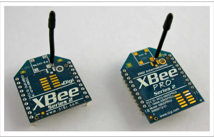
Both the Series 1 and Series 2 radios are available in two different transmission powers, regular and PRO (see Figure 1-1). The regular version is called simply an XBee. The XBee-PRO radio has more power and is larger and more expensive.
Figure 1-1. XBee radios in regular and PRO flavors
con-Series 1 Radios
Series 1 XBee modules are quite popular with the do-it-yourself crowd, while Series 2 hardware supports the full ZigBee protocol. Series 1 is great for simple cable replace-ments and smaller-sized systems. Series 2 is designed with larger sensor networks in mind and is essential for the robust interactions with the ZigBee standards-based sys-tems that are now being widely deployed in residential, academic, and commercial settings.
The Series 2 hardware has a little better range and uses slightly less power than the Series 1; yet these small improvements would not be a reason to choose one format over the other. Both use the same physical footprint and can be easily interchanged, often with only minor changes to the underlying software. However, the Series 2 will not talk to or interoperate with the Series 1 at all. Each network must use only one version. Table 1-1 shows a summary of the similarities and differences.
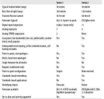
Table 1-1. Series 1 versus Series 2 for regular XBees
Series 1 Series 2
Typical (indoor/urban) range 30 meters 40 meters
Best (line of sight) range 100 meters 120 meters
Transmit/Receive current 45/50 mA 40/40 mA
Firmware (typical) 802.15.4 point-to-point ZB ZigBee mesh
Digital input/output pins 8 (plus 1 input-only) 11
Analog input pins 7 4
Analog (PWM) output pins 2 None
Low power, low bandwidth, low cost, addressable, standar-dized, small, popular
Yes Yes
Interoperable mesh routing, ad hoc network creation, self-healing networks
No Yes
Point-to-point, star topologies Yes Yes
Mesh, cluster tree topologies No Yes
Single firmware for all modes Yes No
Requires coordinator node No Yes
While this book uses the Series 2 hardware exclusively, what you learn here can help you with both series. Picking up the Series 1 commands should be a snap after reading this book because, for the most part, they are a subset of the Series 2 that we cover here. You will already know pretty much everything you need to work with them! Tom Igoe’s excellent volume Making Things Talk (O’Reilly) has several appealing example projects for Series 1 XBees, and many more are available online.
Antennas
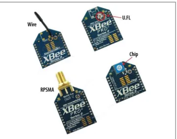
Radios need antennas to transmit and receive signals. There’s more than one way to build an antenna, each with advantages and disadvantages. You probably won’t be surprised to learn that Digi decided to offer plenty of choices. Here are the kinds of antenna options currently available (see Figure 1-2):
Whip or wire antenna
This is just what it sounds like—a single piece of wire sticking up from the body of the radio. In most cases, the wire antenna is just what you need. It’s simple and offers omnidirectional radiation, meaning the maximum transmission distance is pretty much the same in all directions when its wire is straight and perpendicular to the module.
Chip antenna
Again, this is pretty much what it sounds like. The chip antenna is a flat ceramic chip that’s flush with the body of the XBee. That makes it smaller and sturdier, but those advantages come at a price. Chip antennas have a cardioid (heart-shaped) radiation pattern, meaning that the signal is attenuated in many directions. How-ever, if you’re making a device where mechanical stress to the wire antenna might break it, or you need to put the radio in a very small space, then the chip antenna may be your best bet. Chip antennas are often the right choice for anything wearable.
PCB antenna
Introduced with the XBee-PRO S2B, the PCB antenna is printed directly on the circuit board of the XBee. It is composed of a series of conducting traces laid out in a fractal pattern. The PCB antenna offers many of the same advantages (and disadvantages) as the chip antenna with a much lower cost to manufacture. U.FL connector
fragile, and almost always used with a short connecting cable that carries the signal from a remotely mounted antenna.
RPSMA connector
The RPSMA connector is just a different type of socket from the U.FL connector. It’s bigger and bulkier, but you can use it with an external antenna, mounted di-rectly to the XBee without a connecting cable. For most introductory projects, you’re still best off with the simple wire antenna that is smaller, cheaper, and usu-ally just as good.
Figure 1-2. Antenna types
If you need a chip antenna, the part number is XB24-Z7CIT-004. If you require a PRO high-power radio, use part number XBP24BZ7WIT-004.
Vendors
Now that you know what you want to buy, you also need to decide where to buy it. XBee radios are available directly from Digi, and also from many online resellers. This is a list of vendors that typically stock XBees, as well as many other nifty electronic components you may need for your projects:
Digi International
Digi manufactures and sells all varieties of XBee radios and some interesting XBee starter kits, generally at the suggested retail price. They don’t sell any other elec-tronic components.
Maker SHED
MAKE: magazine (which is published by O’Reilly, the publisher of this book) offers a kit specifically designed for this book, via their in-house maker emporium. The kit includes many of the parts you’ll need, including appropriate XBees.
SparkFun Electronics
SparkFun carries a rapidly growing array of prototyping supplies designed specif-ically for DIY electronics enthusiasts, including most of the XBee modules. You’ll find documentation links for each part, as well as handy tutorials for using many of the components.
DigiKey
DigiKey offers a dizzying array of electronic components for the professional electrical-engineering market. It’s normal to feel overwhelmed at first by the se-lection of about half a million different parts, but it’s worth learning the ropes because you’ll be able to buy almost anything you want and receive it the next day. The entire XBee line is usually represented at DigiKey (which has no relationship at all to Digi International).
Part numbers have been supplied for most of the parts recommended in this book. You’ll see the vendors abbreviated in those lists: SparkFun is SFE; DigiKey, DK; Maker Shed, MS; Radio Shack, RS; Adafruit, AF.
Buying an Adapter
you need to connect to an older 9-pin or 25-pin serial port instead, check the Appen-dix for other options.
There are several different adapters available, along with a few handy hacks if you want to avoid buying one or if you get caught without one.
Digi Evaluation Board
If you buy a complete drop-in networking starter kit from Digi, such as their iDigi Professional Development Kit ZB (part no. XK-Z11-PD), it will include an evaluation board with a power supply, a USB connector, and some handy buttons and lights. The kits are a good value if you need everything they include. However, if you only want some radios and an adapter, other approaches are more cost-effective. Also, the Digi evaluation board is substantially larger than most third-party adapters, making it somewhat cumbersome to carry around. At the time of this writing, the development kit was available for $300, though occasional promotions have brought it down to $150. (See Figure 1-3.)
Figure 1-3. Digi evaluation board
USB Adapters
Figure 1-4. XBee adapters are available from many vendors in a variety of different formats
Almost all XBee USB adapters require drivers from FTDI (http://www .ftdichip.com/Drivers/VCP.htm). Be sure to install these before using your adapter.
SparkFun XBee Explorer
The Explorer is a very popular adapter that uses a fairly standard USB A to mini-B cable to connect with your computer. We’ll be using it in most of the examples in this book. The cable is sold separately, but before you buy, check to see if you already have one. Many digital cameras come with this type of cable. Be aware that if you add male headers to use it in a breadboard, the pin order will not be the same as on the XBee. Check the data sheet carefully if you are using the Explorer with a breadboard setup. (About $25; http://www.sparkfun.com/commerce/product_info .php?products_id=8687.)
Adafruit XBee Adapter Kit
New Micros XBee Dongle
One of the smallest adapters, it needs no external cable. The Dongle does not provide any access to the radio beyond USB. Also, because it has no cable, its shape sometimes interferes with other cables or the computer casing. On the other hand, it’s a very small all-in-one device that’s easy to carry in a pocket. It’s terrific for use on the go. (About $39; http://www.newmicros.com/cgi-bin/store/order.cgi?form= prod_detail&part=USB-XBEE-DONGLE-CARRIER.)
Gravitech XBee to USB Adapter
Like the Explorer, this is another simple adapter board that uses the USB A to mini-B cable (not included). This one also has standard breadboard pinouts. (About $28; http://store.gravitech.us/xbtousbad.html.)
Breadboards
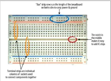
Solderless breadboards (Figure 1-5) provide an easy test bed for hooking up electronic circuits without needing to make permanent connections. They consist of a plastic housing riddled with small holes. Metal clips that lurk beneath the holes in the bread-board provide a way to hold and connect components. Each metal clip is called a bus, and everything attached to the same bus is connected together electrically. Many breadboards have two power and ground buses running down each side, with shorter buses oriented to them at right angles (Figure 1-6). Components like LEDs, capacitors, radios, and microchips are placed in the shorter buses, called terminal strips. These are connected to the power buses and each other using jumper wires.
Breakout Boards
All XBee radios have 20 connection pins, each spaced 2 mm apart. The tight spacing of the pins helps to keep the radios very small, but doesn’t allow them to fit into a solderless breadboard. Luckily, this is a very easy problem to solve. Simple XBee break-out boards that adapt to 0.1″ breadboard spacing (see Figure 1-7) are available from:
• SparkFun • Adafruit • Cutedigi • Gravitech
You will generally need to solder 2 mm female pin headers to one side of these breakout boards, and regular 0.1-inch male headers to the other side.
Note that the XBee Explorer (Figure 1-8), Adafruit XBee Adapter Kit, and the MCPros XBee Simple Board each have mounting holes for 0.1-inch male headers. Solder a set of male header pins into them to adapt these for breadboard use.
Adapters, Breakout Boards, and Shields
In case you are still a bit mystified by the different ways that an XBee radio can be attached to another device, here’s a quick review:
Adapters
Typically used to connect the XBee to a USB port on your computer. Some also provide breakout-board functionality.
Breakout boards
Used to plug your XBee into a standard breadboard and facilitate wired connec-tions to other components, including the Arduino board.
Figure 1-7. Breakout board showing pin spacing
Shields
These attach an XBee directly to an Arduino microcontroller. Shields are printed circuit boards engineered to seat directly on top of an Arduino board. When you are not including other components, the shield eliminates the need for breadboards and wiring.
Arduino Board Adapter Hack
The Arduino microcontroller board we’ll be using in Chapter 4 can be modified to function as an adapter for XBee radios. This is a useful hack if you don’t want to buy an adapter—or anytime you find yourself caught without your regular XBee adapter setup. You’ll still need a breakout board, however.
This hack allows you to connect to the XBee from a terminal program (described later in this chapter). It lets you use some features of X-CTU (also described later), but it does not support firmware upgrades. For that, you should use a proper XBee adapter.
Here’s what you’ll need:
• XBee radio (see “Buying an XBee Radio” on page 1) • XBee breakout board (see “Breakout Boards” on page 10)
• Arduino microcontroller board with USB connection (Uno or similar) (SFE DEV-09950, AF 50)
• USB A-to-B-type cable (AF 62, DK 88732-9002, SFE CAB-00512) • Solderless breadboard (AF 64, DK 438-1045-ND, SFE PRT-09567)
• Hookup wire (22 gauge or similar, different colors) or jumper wire kit (AF 153, DK 923351-ND, SFE PRT-00124)
• Wire strippers (AF 147, DK PAL70057-ND, SFE TOL-08696)
• IC extractor (DK K374-ND, RS 276-1581) or small flat-blade screwdriver (SFE TOL-09146)
These part numbers are prefaced with abbreviations for the suppliers: DK, DigiKey; SFE, SparkFun Electronics; AF, Adafruit; RS, Radio Shack.
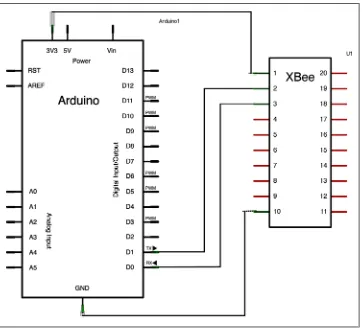
Figure 1-9 shows the Arduino adapter hack breadboard layout, while Figure 1-10 shows the schematic:
1. Make sure that the Arduino is unplugged from the USB and disconnected from any other external power supply before setting up your wiring.
2. Carefully remove the ATMEGA chip from the Arduino, using an integrated circuit (IC) extractor or a small flat-blade screwdriver (when you replace it later, be sure the notch at one end of the chip is aligned with the notch in the socket). Or, if you don’t want to pull the chip, program the Arduino with the following null code, which prevents the Arduino chip’s bootloader from responding accidentally:
void setup() { }
void loop() { }
3. Connect a (red) wire from the 3.3 V socket on the Arduino so that it mates with the XBee’s pin 1, the 3.3 V input pin in the upper-left corner of the XBee.
4. Next, connect a (black) wire from either GND socket on the Arduino so that it mates with pin 10 on the XBee in its lower-left corner.
5. Now wire up a connection from the TX pin (pin 1) on the Arduino to pin 2, the TX/DOUT pin on the XBee. See Table 1-2 and Figures 1-11 and 1-12 for a full list of the XBee’s hardware pins and their functions.
6. Finally, wire a connection from the RX pin (pin 0) on the Arduino to pin 3, the RX/DIN pin on the XBee.
7. Check all your connections. It is very important that you supply only 3.3 V power to your radio.
XBee radios will not work with voltages larger than 3.3. Giving them more than 7 volts will burn them out. When in doubt, remove the radio from your project and confirm the voltage with a multimeter (AF 71, DK BK117B-ND, SFE TOL-09141) before proceeding.
When you’re done with the hack, set it aside for now. You won’t need to power up this circuit until you get to “Configuring XBee” on page 40 in Chapter 2.
Figure 1-9. Arduino adapter hack breadboard layout
What Are All Those Pins?
Table 1-2. XBee pin descriptionsPin # Name(s) Description
1 VCC 3.3 V power supply
2 DOUT Data Out (TX)
3 DIN Data In (RX)
4 DIO12 Digital I/O 12
5 RESET Module reset (asserted low by bringing pin to ground)
6 PWM0/RSSI/DIO10 Pulse-width modulation analog output 0, Received Signal Strength Indicator, Digital I/O 10
7 DIO11 Digital I/O 11
8 Reserved Do not connect
9 DTR/SLEEP_RQ/ DIO8 Data Terminal Ready (hardware handshaking signal), Pin Sleep Control (asserted low), Digital I/O 8
10 GND Ground
11 DIO4 Digital I/O 4
12 CTS/DIO7 Clear to Send (hardware handshaking), Digital I/O 7 13 ON/SLEEP Sleep indicator (off when module is sleeping)
14 VREF Not used in Series 2
15 ASSOC/DIO5 Association indicator: blinks if module is associated with a network, steady if not; Digital I/O 5
16 RTS/DIO6 Request to Send (hardware handshaking), Digital I/O 6 17 AD3/DIO3 Analog Input 3, Digital I/O 3
18 AD2/DIO2 Analog Input 2, Digital I/O 2 19 AD1/DIO1 Analog Input 1, Digital I/O 1
20 AD0/DIO0/COMMIS Analog Input 0, Digital I/O 0, Commissioning Button
Choosing a Terminal Program
Figure 1-11. XBee physical pin numbering, front view
To change or upgrade the firmware, we will use a program called X-CTU that you can download from the Digi website. On the upside, this program is totally free. On the downside, it runs only on Windows. Don’t worry if you have limited access to Win-dows, though. Chances are you’ll only need X-CTU initially, to load the proper firm-ware onto your XBee radio. Going forward, you can use serial terminal programs on Macintosh, Linux, or Windows to change many of the settings you’ll be working with on a day-to-day basis. Let’s take a look at some of these programs and how they operate.
Firmware Update Software
There is only one option for updating the low-level firmware on XBee radios: Digi’s configuration tool, which is available for free.
X-CTU
The X-CTU program is the official configuration program for XBee radios. As noted, X-CTU is available only for the Microsoft Windows operating system. If you have ac-cess to a native Windows computer, a Macintosh running Windows under Boot Camp or Parallels, or a Linux computer running the WINE Windows emulator (see “X-CTU in Linux” on page 33 in Chapter 2), you’re all set. Luckily X-CTU is required only for updating firmware, which is a relatively infrequent task. It does have a number of other handy features, though, including fully commented setup commands, range tests, and easier access to the API features we’ll be examining in Chapter 5.
To use X-CTU, plug your XBee radio into a USB adapter and plug that adapter into one of your computer’s USB ports. Next, launch the X-CTU program. It should show your USB connection as one of the available ports, similar to what you see in Fig-ure 1-13. Select the appropriate port and then click on the Modem Configuration tab to get to a basic configuration screen (Figure 1-14). Clicking on the Read button will generally access the radio’s setup, though this depends upon which firmware is cur-rently loaded. Don’t be concerned if you get an error message instead. We’ll go over the details in the next chapter.
Terminal Software for Configuring Settings
CoolTerm
CoolTerm is a terrific open source serial terminal program created by Roger Meier that runs well on both Windows and Macintosh. It’s a relatively simple program that’s perfect for most basic tasks you need to perform with XBee radios. CoolTerm is free. Consider making a small donation to show your appreciation and encourage continued support for the program (http://freeware.the-meiers.org).
HyperTerminal
Tera Term
Tera Term is a free, open source Windows program that performs a wide variety of terminal functions, including acting as a serial terminal. Those using Vista or Windows 7 will appreciate having a free option, since HyperTerminal is no longer bundled with Windows and must be purchased separately. This is the Windows software we’ll use to demonstrate serial terminal use (http://ttssh2.sourceforge.jp/).
ZTerm
stable for almost 20 years. You’ll find some brief setup documentation on my blog, and you can download ZTerm and pay its small shareware fee online (http://homepage.mac .com/dalverson/zterm/).
screen
For Linux users and for those comfortable in the Macintosh Terminal, there’s a command-line program named screen that allows direct access to serial ports, including
USB devices. On Mac OS X, the command ls dev/tty.* will list the available ports, returning a list like this:
/dev/tty.Bluetooth-Modem /dev/tty.Bluetooth-PDA-Sync /dev/tty.usb-A410032.
On Linux, try ls dev/ttyUSB*. Your serial port will probably be something like /dev/ ttyUSB0.
Once you know what your USB port is called, you can invoke the screen program, using
the port and a data rate of 9600 baud. For example: screen /dev/tty.usb-A410032 9600
To exit, type Ctrl-A followed by Ctrl-\ and then y to quit.
The picocom program, described in the sidebar “A Serial Terminal Program for Li-nux” on page 40 in Chapter 2, is an alternative to screen and has certain features
(such as local echo) that can be useful for working with XBees.
Others
Here are some other popular options for serial terminals. Some are free, and some aren’t:
• RealTerm • Termite • PuTTY • MacWise
Summary
Here is a basic shopping list that will work well for this book. Feel free to customize it according to your interests and the projects you have planned:
• Three XBee ZBs with wire antenna (Digi: XB24-Z7WIT-004, DK602-1098-ND) • One or two XBee Explorers (SFE: WRL-08687)
• One or two USB A to Mini-B cables (SFE: CAB-00598) • X-CTU for Windows (free)
CHAPTER 2
Up and Running
Here is the heart of the book. We go from a bag of parts to a working ZigBee network in one chapter, taking the simplest path to early success. Addresses, firmware, and configuration steps culminate in a simple chat session for a satisfying exchange of greetings. Hello world, you are up and running.
Let’s get started.
Radio Basics
Electromagnetic Spectrum
Radio is only one slice of the broad array of energy we call the electromagnetic spectrum (see Figure 2-1). This spectrum includes high-power gamma rays that arrive from su-pernovas in outer space, the X-rays we use to sneak a peek at broken bones, microwaves that cook our food, infrared that we sense broadly as heat, and the one tiny slice of the spectrum that about a third of our brain is devoted to decoding: visible light. Radio waves are much longer than light waves and many can travel through opaque substan-ces such as clothing, furniture, and brick walls. Radio energy requires no medium. It can propagate perfectly well in a vacuum and is therefore ideal for communications where metal wire connections are impractical, or where visual line of sight may be impeded by obstructions. When radio waves impinge on a conductor, like metal, they induce an electrical current that transforms their energy into another form. This means that radio will not travel well through metal walls, but it also means that we can employ metallic antennas to transduce radio energy into electrical signals that computers can detect and process. Engineers have a comprehensive body of theories, equations, and laws for predicting and manipulating the behavior of radio. Luckily, we can make do for the time being with just one of these tools, the inverse square law.
Figure 2-1. Chart of the electromagnetic spectrum
Inverse Square Law
Radio signals require a lot of power because, unlike messages running through a wire, they decay in an accelerated fashion. The reason for this is easy to understand. As radio signals radiate away from their source, they rapidly spread out like ripples in a pool. Sound works pretty much the same way, which is why it’s easy to hear a whisper up close, but impossible to understand it even a few feet away. Both sound and radio decay according to the inverse square law. Each time you double the distance, you require four times the amount of power (as Figure 2-2 shows), so traversing long distances requires tremendous expenditures of energy compared to shorter ones.
Introduction to ZigBee
Many people think that ZigBee and XBee are the same thing. That’s not true. ZigBee is a standard communications protocol for low-power, wireless mesh networking. XBee is a brand of radio that supports a variety of communication protocols, including Zig-Bee, 802.15.4, and WiFi, among others.
The ZigBee protocol is a standard the same way that Bluetooth is a standard. Any manufacturer’s device that fully supports the ZigBee standard can communicate with any other company’s ZigBee device. So just as your Motorola Bluetooth headset can communicate with your Apple iPhone, a CentralLite ZigBee light switch can commu-nicate with a Black & Decker door lock. How does this work? Well, just like a great cake, robust network protocols are all about layers.
Most modern network protocols employ a concept of layers to separate different com-ponents and functions into independent modules that can be assembled in different ways. We’re not going to bother with a lot of network theory here, just enough for you to complete the tasks at hand.
Every network has a physical layer where signals are actually transmitted. For example, your computer may be connected via an Ethernet cable to the Internet. On the other hand, it may be going wireless with a WiFi connection, using radio signals to traverse the real world. That’s all happening in the physical layer, and doesn’t change a thing about, for example, what’s going on at the application layer, which is where your web browser lives. Firefox doesn’t care a whit if you switch from Ethernet to WiFi. It is protected by the interfaces between layers that allow each software and hardware module to change how it does its job, but still talk to the other layers in exactly the same way.
Another way to conceptualize this is to consider your car. You can drive over concrete highways, asphalt driveways, metal bridges, and dirt parking lots without changing vehicles. Your tires provide an interface between the vehicle layer and the road layer. It would work just as well if you were driving a motorcycle or an ice cream truck. Either layer can be changed out independently without affecting the other.
The network layer below ZigBee that supports its advanced features is known as IEEE 802.15.4. This is a set of standards that define power management, addressing, error correction, message formats, and other point-to-point specifics necessary for proper communication to take place from one radio to another. XBee-brand radios can be purchased with or without ZigBee. For example, the XBee Series 1 hardware—which we don’t work with in this book (but do mention in Chapter 1)—supports 802.15.4 directly in its native form. ZigBee is a set of layers built on top of 802.15.4. These layers add three important things:
Routing
Routing tables define how one radio can pass messages through a series of other radios along the way to their final destination.
Ad hoc network creation
This is an automated process that creates an entire network of radios on the fly, without any human intervention. Pretty cool.
Self-healing mesh
Self-healing is a related process that automatically figures out if one or more radios is missing from the network and reconfigures the network to repair any broken routes.
A ZigBee network is a little like a basketball team. Both are composed of various players, and each player specializes in certain types of actions. Without the different players, neither can function properly. Of course, ZigBee is not quite basketball. For one thing, the radios are not particularly tall. Also, there are really only three kinds of players, or device types. Every ZigBee network will have a single coordinator device. You can’t call anything a network until you have at least two things connected. So every ZigBee net-work will also have at least one other player, either a router device or an end device. Many networks will have both, and most will be much larger than just two or three radios:
Coordinator
ZigBee networks always have a single coordinator device. This radio is responsible for forming the network, handing out addresses, and managing the other functions that define the network, secure it, and keep it healthy. Remember that each net-work must be formed by a coordinator and that you’ll never have more than one coordinator in your network.
Router
infor-messenger for communications between other devices that are too far apart to convey information on their own. Routers are typically plugged into an electrical outlet because they must be turned on all the time. A network may have multiple router radios.
End device
There are many situations where the hardware and full-time power of a router are excessive for what a particular radio node needs to do. End devices are essentially stripped-down versions of a router. They can join networks and send and receive information, but that’s about it. They don’t act as messengers between any other devices, so they can use less expensive hardware and can power themselves down intermittently, saving energy by going temporarily into a nonresponsive sleep mode. End devices always need a router or the coordinator to be their parent device. The parent helps end devices join the network, and stores messages for them when they are asleep. ZigBee networks may have any number of end devices. In fact, a network can be composed of one coordinator, multiple end devices, and no routers at all.
Network Topology
In basketball, once the players are selected, they still need to assemble as a team. ZigBee networks are the same way. They can connect together in several different layouts or topologies to give the network its structure. These topologies indicate how the radios are logically connected to each other. Their physical arrangement, of course, may be different. There are three major ZigBee topologies, illustrated in Figure 2-3:
Pair
The simplest network is one with just two radios, or nodes. One node must be a coordinator so that the network can be formed. The other can be configured as a router or an end device.
In general, projects that will never need more than a single pair of radios won’t get much advantage out of ZigBee and should con-sider using the simpler Series 1 802.15.4 protocol radios discussed in Chapter 1.
Star
Mesh
The mesh configuration employs router nodes in addition to the coordinator radio. These radios can pass messages along to other routers and end devices as needed. The coordinator (really just a special form of router) acts to manage the network. It can also route messages. Various end devices may be attached to any router or to the coordinator. These can generate and receive information, but will need their parent’s help to communicate with the other nodes.
Cluster tree
This is a network layout where routers form a backbone of sorts, with end devices clustered around each router. It’s not very different from a mesh configuration.
Addressing Basics
Then there’s a shorter 16-bit address that is dynamically assigned to each radio by the coordinator when it sets up a network. This address is unique only within a given network, but since it’s shorter, many more of them can be manipulated in the very limited memory available on a ZigBee chip. Finally, each XBee radio can be assigned a short string of text called the node identifier. This allows the radio to be addressed with a more human-friendly name. Four out of five humans prefer a friendly machine.
Table 2-1. Address types
Type Example Unique
64-bit 0013A200403E0750 Yes, always and everywhere
16-bit 23F7 Yes, but only within a network
Node identifier FRED’S RADIO Uniqueness not guaranteed
PAN Addresses
In the United States, nearly every town has a Main Street. Thousands of different fam-ilies live at, for example, 123 Main Street. We can tell them apart because while their street address is the same, their town or city is different. Each ZigBee network creates a virtual “city” in the same way, and labels that city not with a name but with a number, the Personal Area Network (PAN) address. This is another 16-bit address. There are 65,536 different PAN addresses available, each having the capability to generate an-other 65,536 16-bit radio addresses below it. In theory, therefore, this addressing scheme has room for more than 4 billion total radios, more than you’ll ever need, no matter how ambitious a project you may have planned!
Channels
Even if all the addressing is perfect, your message still won’t get through unless both radios are tuned to the same frequency. When the ZigBee coordinator picks a network PAN address, it also checks over all the available channels, typically 12 different ones, and picks a single one for that network’s conversations. All the radios in that network must use the same channel. By default, XBee radios handle channel selection automat-ically so you usually don’t need to worry about this, unless of course something goes wrong.
All Together Now
we describe. For now, remember that you’ll need a PAN and a radio address to get your messages through. You’ll learn how these are set up in the next sections.
You may run into terminology regarding ZigBee application layer ad-dressing, including discussions of ZigBee profiles, clusters, and end-points. You won’t need these terms to do the projects in this book, so they are mentioned here only to reassure you that you can safely ignore them for now. We will cover application layer concepts in Chapter 8.
Figure 2-4. Venn diagram showing channel, PAN, and addressing
Hexadecimals
There’s no question about it: if you want to use an XBee, you’ll need to understand hexadecimal notation. Every time you set an XBee’s address, configure one of its timers, or read the signal strength, the numbers you use are all formatted in base 16.
Relax! It’s pretty easy and we’re going to show you everything you need to know about these special numbers. If you’ve worked with computers at all, you’ve almost certainly seen these numbers, called hexadecimals, hex, or base 16 (these all mean the same thing).
Normally, we express numbers in base 10, counting with numerals from 0 to 9, then
carrying to the next place to get 10 like this: 1...2...3...4...5...6...7...8...9...10
7 4 5 3 thousands hundreds tens ones 103 102 101 100
This probably looks pretty familiar. However, if you came from another planet and didn’t know how to read decimals, you could multiply each number by its place to get the total value. (7 * 1,000) + (4 * 100) + (5 * 10) + (3 * 1) = 7,453. Hold that thought; this method will come in handy below.
You might be interested to learn that decimal is only one of many ways to write down numbers. Imagine how compact your notation would be if you could count from 0 to 15 before you had to carry to the next place, for example:
1...2...3...4...5...6...7...8...9... UH-OH!
We don’t have a single numeral to express 10! We could make up a new squiggle and that would work fine, except it would be easier if we could use something already on the computer keyboard. So let’s just use the letter A and say that stands for 10. We can then use the letter B to stand for 11, and so forth:
1...2...3...4...5...6...7...8...9...A...B...C...D...E...F...10
It may look weird but we didn’t make a mistake at the end. F stands for 15, and then to express 16 we carried so we had 1 in the sixteens place and 0 in the ones place:
1 0 sixteens ones 161 160
That’s right, in hexadecimal the notation 10 means 16. To avoid confusion, we usually mark hexadecimal numbers in a special way, with a leading zero and a letter x, like this: 0x10. The leading zero and x don’t mean that we’re multiplying by zero or anything. They’re simply a prefix, like the dollar sign, to let us know what kind of notation will follow. So if you see the hexadecimal 0x7E2 here’s how to break it down:
7 E 2 two-hundred-fifty-sixes sixteens ones 162 161 160
So what number is this anyway? Remember that multiplication exercise we did with decimals? Let’s try it with this unfamiliar hexadecimal. (7 * 256) + (E * 16) + (2 * 1) = ?? Oh bother, we need to translate that letter E into its decimal form. Let’s do that right now: (7 * 256) + (14 * 16) + (2 * 1) = 2,018.
Try translating these decimals into hex. The first few are filled in to get you started: 10 = 0xA
16 = 0x10 17 = 0x11 18 = ___
Now try translating these hexadecimals into decimals: 0xFF = ___
0x3 = ___ 0x4B = ___ 0x4C = ___ 0x186A0 = ___
That last one is hard, so it’s only fair to tell you now that both Windows and Macintosh have hex calculators. On the regular Windows calculator, change the View menu from Standard to Scientific. On the Macintosh calculator (Figure 2-5), change the View menu to Programmer. Now, click the Dec and Hex buttons to switch from decimal to hexa-decimal notation. You were promised easy, and what could be simpler than clicking a button? Enjoy.
Figure 2-5. Mac calculator in programmer mode
XBee Firmware Updates
The X-CTU program and installation instructions are available at http://www.digi.com/ support/kbase/kbaseresultdetl.jsp?kb=125. During the installation process, if you are asked if you want to download new firmware versions, go ahead and get them. In addition to X-CTU, you’ll need to install the appropriate drivers for your XBee adapter board. Most adapter boards, such as the SparkFun XBee Explorer and the New Micros XBee Dongle, use FTDI drivers. The drivers and installation instructions are located at http://www.ftdichip.com/FTDrivers.htm. Windows may be able to discover the drivers on its own if you have Windows Update enabled and are connected to a network.
X-CTU in Linux
To use X-CTU under Linux, you’ll need to first install Wine, which lets you run Win-dows applications under the X Window System. On a Linux system, you can usually install Wine using your Linux package manager.
Next, using Wine, download the X-CTU installer and run this command:
wine 40002637_c.exe
(If the filename is not 40002637_c.exe, replace it with the name of the file you downloaded.)
Now create a symbolic link between the serial port that corresponds to your XBee and a Windows serial port, such as COM10:
ln -s /dev/ttyUSB0 ~/.wine/dosdevices/com10
The actual device filename (ttyUSB0 in the example) will vary, so look at the output of the dmesg command shortly after you plug in the XBee adapter to see which device was
added.
Next, launch X-CTU using a command something like:
wine .wine/drive_c/Program\ Files/Digi/XCTU/X-CTU.exe
Click the User Com Ports tab and type in the name of the Com port you created (such as COM10), then click Add. Unfortunately, you will need to do this each time you launch X-CTU, as it does not remember the custom Com ports.
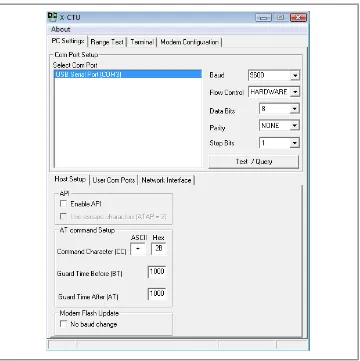
Plug one of your XBee radios into your XBee adapter and connect the adapter to one of your Windows computer’s USB ports. Launch the X-CTU application. You should see your XBee’s USB connection listed under Select Com Port. Click on the appropriate port to select it, as shown in Figure 2-6.
Figure 2-6. X-CTU starting screen
If you get the message “Unable to communicate with modem,” make sure your XBee is seated properly in its adapter, that it isn’t too far for-ward or back by a pin, and that it wasn’t inserted backfor-ward (see Figures
2-8 and 2-9). Also, check to make sure you selected the correct COM port. (If you suspect that your XBee may be using the API firmware, try checking the Enable API Mode box. API mode is covered in Chap-ter 5.) It’s also possible that your XBee has been configured to a baud rate different from the default of 9600 baud. Try switching to one of the other baud rates and trying again. If you still can’t get an OK response to the test, don’t despair. Most of the time, your hardware is just fine. There are plenty of other fixes you can attempt. Check the Appendix
for additional troubleshooting steps, or contact Digi for technical sup-port at http://www.digi.com/support. Sometimes, just moving on to the next step helps with connection issues, so let’s do that now.
Figure 2-8. An XBee misaligned and seated incorrectly. Note that one of the metal pins is showing ahead of the socket. This radio will not work until it is properly reseated.
Reading Current Firmware and Configuration
Note the “Download new versions” button. Use this button occasionally to have X-CTU check the Digi website for new versions of firmware (click “Download new ver-sions,” then click Web).
Linux Troubleshooting
If you’re running X-CTU under Wine on Linux, you may see a dialog box that tells you the modem configuration file could not be found. This dialog will offer to download the latest configuration files from the website. If it fails:
1. Visit the Digi FTP site.
2. Next, look in both the xbee_s2 (series 2) and xbee_zb (ZigBee firmware) subdir-ectories to find the firmware file that matches what you saw in Figure 2-7 (for example, XB24-ZB_2041.zip for a regular XBee, XBP24-ZB_2041.zip for an XBee-PRO).
3. Then, find the highest numbered XB (for XBee) or XBP (for XBee-PRO) firmware in the xbee_zb directory, sort by date, and download all of the most recent available ZIP files. For example, at the time of this writing, the most recent firmware files for the regular XBee were XB24-ZB_2070.zip, XB24-ZB_2170.zip, XB24-ZB_2270.zip, XB24-ZB_2370.zip, XB24-ZB_2870.zip, and XB24-ZB_2970.zip. 4. In X-CTU, go to the Modem Configuration tab, click Download New Versions,
and use the File option to install each of the files (one at a time, unfortunately) you just downloaded.
5. Click the Read button again, and X-CTU should recognize your XBee.
The Modem type listed needs to be XB24-ZB or XBP24-ZB. Modem types XB24-B, XB24P-B, XB24-SE, and XB24P-SE can be updated to the ZB firmware. If you see another model listed when you Read from the radio, it may not be the correct hardware, in which case it will not work with this book. Chapter 1 has information on where to obtain the correct hardware.
If you get a dialog box that says there’s a problem (Figure 2-11), with a suggestion for pressing the XBee reset switch, try gently pulling the XBee out of its socket on the adapter and reseating it. Be sure to wait 10 sec-onds for X-CTU to recognize the radio; after it does, it will close the dialog box on its own.
Doing this while the adapter is still plugged in effectively resets it. The Digi Evaluation Board has a reset button, so if that’s your adapter, sim-ply press the button.
Figure 2-11. If you get this message, you can reset the XBee by gently pulling it out of its socket and reseating it
Let’s configure the first XBee:
1. The class of radio modem is shown under Modem: XBEE (Figure 2-10). For ev-erything we do in the main part of this book, it should be XB24-ZB (or XBP24-ZB if you’re using the higher-power PRO version of the radios). If it’s set to something else, select either of these options from the menu.
3. Click on the Write button to program your radio with the coordinator firmware. For later reference, use a piece of tape or a small sticker to identify this radio as the coordinator.
If you get a Windows error such as “Could not open output file. System error. Access denied.”, check that your account has ad-ministrator access.
Once you’ve installed your first radio with the coordinator AT command software, gently remove that radio from the adapter and carefully seat a second radio in the same adapter. Click on Read in the Modem Configuration screen to see what firmware is on that radio, then select XB24-ZB (or XBP24-ZB for PRO radios), ZIGBEE ROUTER AT, and the highest-number version available. Any version 2270 or greater should be fine. Again, click on Write to program your second radio with the router firmware. Mark the router radio as well to identify it.
If your radio has API firmware and you had to check the Enable API box on the PC Settings tab, when you switch to AT command firmware, the last step of the update may fail with a message about an “Error Setting AT Parameters” (Figure 2-12). You can safely ignore this error, change back to the PC Settings tab, uncheck the Enable API box, and then select the Modem Configuration tab and Read in the Modem Parameters again. Phew!
Figure 2-12. Error when switching from API to AT firmware
Configuring XBee
Any time you aren’t able to use X-CTU, you can configure any XBee that’s in AT com-mand mode by using a serial terminal program. In the previous chapter we covered a variety of serial terminal software. Here we’ll show two different programs, Tera Term for Windows and CoolTerm for Macintosh (CoolTerm also works on Windows).
A Serial Terminal Program for Linux
If you’re on Linux, you’ll probably find picocom to be a suitable terminal program. The newer versions of picocom support local echo, which lets you see what you’re typing. To use picocom, you’ll need to compile and install it, then run it at the command line. For example, to connect to the first USB-serial port (if you’ve only got one XBee plugged into your Linux system, it will probably be this port), use:
picocom --echo --imap crcrlf /dev/ttyUSB0
You can exit picocom by typing Ctrl-A followed by Ctrl-X.
Settings
No matter what program you use, you’ll need to configure your software to use the communication settings shown in Table 2-2.
Table 2-2. Default XBee settings for serial terminal software
Baud 9600
Data 8 bit
Parity None
Stop bits 1
Flow control None
Line feed CR+LF or Auto Line Feed Local echo On
Ports
can see a list of ports by opening the Terminal program, typing ls /dev/tty.* (Linux
users should use ls /dev/ttyUSB*), and then pressing the Return key.
Connecting from Windows
To begin using your XBee via Tera Term on Windows, plug the XBee adapter into one of your USB ports and launch the Tera Term application. Tera Term can generally be selected right from the Windows Start menu. The opening screen (Figure 2-13) will prompt for a new connection.
Figure 2-13. Tera Term opening screen
Select Serial on the “New connection” screen, then choose the port that is connected to your XBee adapter. Click on OK and you should see a blank Tera Term window. Choose Terminal from the Setup menu. In the dialog box that’s presented ( Fig-ure 2-14), choose CR+LF for New-line Receive and check the “Local echo” box. Click OK to close this panel.
Next, select Serial from the Setup menu to confirm that the communication settings are correct. You’ve already selected your port, and the default of 9600 baud, 8 data bits, no parity, one stop bit, and no flow control will be perfect (Figure 2-15). Click OK to close the panel.
Figure 2-14. Tera Term terminal setup