Programming
with Data
Environments
I
n this c hapter, I’m go ing to disc uss ho w to use the Data Enviro nment Designer to c reate a Data Enviro nment, whic h simplifies many o f the tasks o f building a database applic a-tio n. It explo its the ADO o bjec t mo del and helps yo u c reate standardized ADO o bjec ts that simplify ac c ess to the database.The Data Environment Designer
The Data Enviro nment Designer is a to o l in the Visual Basic IDE that helps a pro grammer c reate a database applic atio n mo re quic kly than if they had to perfo rm the same tasks man-ually. The Designer c reates ADO o bjec ts c o rrespo nding to the tables in yo ur database; it also pro vides o ther o bjec ts to help yo u manipulate yo ur database. These o bjec ts are available as part o f the Data Enviro nment o bjec t at runtime.ADO, not DAO and RDO:The Data Environm ent Designer only w orks w ith the ADO object m odel. The DAO and RDO object m odels are not supported. The UserConnection designer is a subset of the Data Environm ent Designer and supports the RDO object m odel.
Enabling the Data Environment Designer
To add the Data Enviro nment Designer to yo ur pro jec t, c ho o se Pro jec t➪Add Data Enviro nment fro m the main menu. If yo u do n’t see it listed direc tly under the Pro jec t menu, try lo o king under the Mo re Ac tiveX Designers menu (o r Pro jec t➪Mo re Ac tiveX Designers➪Data Enviro nment fro m the main menu). This will display the main win-do w fo r the Data Enviro nment Designer.
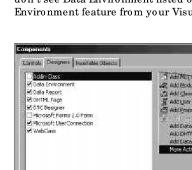
If the Data Enviro nment Designer do esn’t appear in either lo c atio n, yo u’ll need to add it to Visual Basic . Cho o se Pro jec t➪Co mpo nents fro m the main menu to display the Co mpo nents dialo g bo x, then selec t the Designer tab to see the windo w as sho wn in Figure 9-1. Plac e a c hec k mark in the bo x next to Data Enviro nment and press OK. This will add the Data Enviro nment Designer to the Pro jec t menu. If yo u do n’t see Data Enviro nment listed o n the Designers tab, yo u need to install the Data Enviro nment feature fro m yo ur Visual Basic CD-ROM.
Figure 9-1: Adding the Data Environm ent Designer to the Visual Basic IDE
Exploring the Data Environment Designer
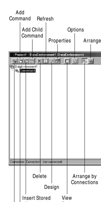
Figure 9-2: Exploring the Data Environm ent Designer w indow
✦Add Conne ction– adds a new Connectiono bjec t to the data enviro nment, whic h will be used to ac c ess a database.
✦Add Command– adds a new Commando bjec t to the data enviro nment, whic h will be used to exec ute an SQL c o mmand.
✦Inse rt Store d Proce dure– adds a Commando bjec t with the info rmatio n to c all a sto red pro c edure o n the database server.
Add Command
Add Connection
Add Child Command
Delete
Insert Stored Procedure
Design Refresh
View Code
Options
Properties Arrange by Objects
Icon tree
✦Add Child Command– adds a Commando bjec t to ano ther Commando bjec t to c reate a hierarc hic al struc ture o f data.
✦De le te– remo ves an o bjec t fro m the data enviro nment.
✦Re fre sh – refreshes the selec ted o bjec t. Connectiono bjec ts are c lo sed and reo pened, while all o f the metadata asso c iated with a Commando bjec t will be rebuilt.
✦De sign– ac c esses the SQL query designer when yo u spec ify an SQL statement as the data so urc e fo r a Commando bjec t.
✦Prope rtie s – displays the pro perties asso c iated with the selec ted o bjec t.
✦Vie w Code– displays the c o de asso c iated with a partic ular o bjec t.
✦Options– displays the Optio ns dialo g bo x that c o ntro ls ho w the Data Enviro nment Designer wo rks.
✦Arrange by Conne ctions– arranges the o bjec ts in the ic o n tree by the
Connectiono bjec t they ac c ess.
✦Arrange by Obje cts– arranges the o bjec ts in the ic o n tree by o bjec t type.
✦Icon Tre e – the list o f o bjec ts asso c iated with the data enviro nment.
Many of these functions are also available via a pop-up m enu that you can display by right clicking on an object in the icon tree.
Data Environment building blocks
The Data Enviro nment Designer helps yo u c reate three main types o f o bjec ts:
Connections, Commands, and Recordsets. These o bjec ts are used at bo th design time and runtime to ac c ess yo ur database. At design time, info rmatio n abo ut yo ur database is extrac ted and made available to help yo u c reate yo ur pro gram. At run-time, these o bjec ts are used to perfo rm typic al database o peratio ns.
It’s not what it seems: While these objects appear to be part of the Data Environ-m ent Designer, they are really norEnviron-m al ADO objects that the Data EnvironEnviron-m ent Designer helps you create. For m ore inform ation about all of the capabilities of these objects, please refer to Chapter 11.
Connection objects
A Connectiono bjec t c o ntains the pro perties and metho ds needed to ac c ess a database. Sinc e the Connectiono bjec t is used at bo th runtime and design time, a related o bjec t c alled the DECconnectionis used by the Data Enviro nment Designer to trac k info rmatio n abo ut eac h mo de. This info rmatio n c o ntains the user name, passwo rd, ho w to pro mpt fo r passwo rd info rmatio n, and whether to save passwo rd info rmatio n at the end o f the sessio n fo r bo th runtime and design-time use.
Command objects
A Commando bjec t c o ntains the info rmatio n nec essary to exec ute a c o mmand against yo ur database. A c o mmand may be an SQL statement, a c all to a sto red pro -c edure, o r the name o f a table. So me -c o mmands will require yo u to in-c lude a list o f parameters when they are run. So me c o mmands will return a set o f ro ws, while o th-ers will return no thing but a status c o nditio n.
Recordset objects
Ro ws are returned fro m yo ur database in a Recordseto bjec t. The Rec o rdset o bjec t presents a single ro w o f data, kno wn as the curre nt re co rd. A curso ris used to po int to the c urrent rec o rd in the Recordset. Yo u c an manipulate the c urso r by using vario us metho ds in the Recordseto bjec t.
If the ro ws in the Recordseto bjec t c an be updated, there are o ther metho ds that Controlwith the appro priate Recordseto b jec t b y c hanging the DataSource
pro perty o n eac h o f the b o und c o ntro ls.
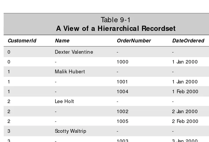
Hierarchical Recordsets
A hierarc hic al rec o rdset is based o n a no rmal Recordset, exc ept that in plac e o f o ne o f the values in a ro w o f data is ano ther Recordset, kno wn as a childrec o rdset. The c hild rec o rdset is c reated by a c hild Command, who se values are determined by a relatio nship with the parent rec o rdset. It is also reaso nable fo r a c hild rec o rdset to have its o wn c hild rec o rdsets, thus c reating a multi-level hierarc hy.
Hierarc hic al rec o rdsets are useful when yo u want to retrieve data fro m multiple tables, but do n’t want to merge the data into a single table. The c lassic c ase o f a hierarc hic al rec o rdset is the c usto mers, o rders, and o rder items. A c o mpany has a c o llec tio n o f c usto mers, eac h c usto mer may have plac ed multiple o rders, and eac h o rder a c usto mer has plac ed may have multiple items.
Connecting to Your Database
The first step in wo rking with the Data Enviro nment Designer is to define a c o nnec -tio n to the database. By default the Data Enviro nment Designer c reates a single
Setting Connection properties
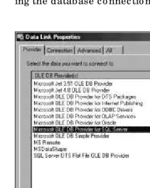
Selec ting the Connection1o bjec t and pressing the Pro perties butto n displays the Data Link Pro perties dialo g bo x, as sho wn in Figure 9-3. While there are fo ur tabs o n the dialo g bo x, o nly the Pro vider and Co nnec tio n tab are typic ally used. The Advanc ed tab c o ntains info rmatio n regarding netwo rk settings, c o nnec tio n timeo ut, and ac c ess permissio ns who se default settings are almo st always o kay. The All tab lists all o f the initializatio n parameters that will be used when establish-ing the database c o nnec tio n.
Figure 9-3: Setting Data Link properties for a Connection object
Selecting an OLE DB provider
The first step in defining yo ur c o nnec tio n to the database is to c ho o se an OLE DB pro vider o n the Pro vider tab o f the Data Link Pro perties dialo g bo x. All o f the pro -viders available fo r yo ur system will be listed. Yo u sho uld c ho o se the native OLE DB pro vider fo r yo ur database server, if o ne is available. Otherwise, yo u sho uld c ho o se the Mic ro so ft OLE DB Pro vider fo r ODBC Drivers. Onc e yo u selec t the pro per OLE DB pro vider, press Next to c o ntinue defining the c o nnec tio n pro perties.
Entering connection information
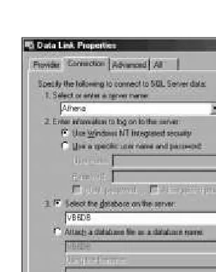
Onc e I enter this info rmatio n, I c an press the Test Co nnec tio n butto n to verify that everything is c o rrec t. If there is a pro blem, a message bo x will be displayed with a desc riptio n o f the erro r; o therwise, a message bo x saying Test c o nnec tio n suc -c eeded will be displayed. After pressing OK o n the test’s message bo x, press OK to save the c o nnec tio n info rmatio n.
Figure 9-4: Entering connection inform ation for the Microsoft OLE DB Provider for SQL Server
The inform ation entered in the Data Link dialog boxes is used to build a connection string. This value is used anytim e you w ant to connect an ADO object to a database. For m ore inform ation about connection strings, see the ConnectionString prop-erty and the Connectionobject in Chapter 11. For details about how to connect to a specific database, see Connecting to SQL Server in Chapter 23, Connecting to Oracle8iin Chapter 26, or Connecting to Jet in Chapter 29.
Creating Commands with the Designer
After yo u have defined a Connectiono b jec t, yo u c an b egin to define so meCommando b jec ts. The Data Enviro nment Designer treats Commando b jec ts in two different ways — as c o mmands and as sto red pro c edures. The differenc e is primar-ily ho w the info rmatio n fo r the o b jec ts is o b tained. If yo u c ho o se to add a sto red pro c edure, the designer will get a list o f sto red pro c edures fro m the datab ase, yo u will need to enter a single, dynamic ally exec uted SQL statement as o ne o f the pro p-erties o f the Commando b jec t. Sto red pro c edures are disc ussed later in this c hapter under “Selec ting a Datab ase Ob jec t.”
Adding a command
Adding a Commando b jec t b y pressing the Add Co mmand b utto n o n the Data Enviro nment Designer to o lb ar simply adds a new c o mmand o b jec t b eneath the c urrently selec ted Connection. All o f the pro perties asso c iated with the Command
o b jec t are left at their default values and must b e c hanged in o rder to use the c o mmand.
Setting general command properties
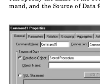
Pressing the Pro perties butto n o r right c lic king o n the Commando bjec t will display the Command1Pro perties dialo g bo x as sho wn in Figure 9-5. On the General tab, yo u c an spec ify the name o f the c o mmand, whic h c o nnec tio n will be used by the c o m-mand, and the So urc e o f Data fo r the c o mmand.
Figure 9-5: View ing the general properties of the Com m and1 object
The So urc e o f Data sec tio n is so mewhat misleading sinc e a Commando bjec t need no t return data. It really depends o n whether the database o bjec t yo u selec t o r the SQL statement yo u enter returns any data.
Selecting a database object
Yo u have a c ho ic e o f fo ur different database o bjec ts: a Sto red Pro c edure, a Table, a View, o r a Syno nym. A sto re d pro ce dure is no thing but a series o f o ne o r mo re SQL statements that are exec uted o n the database server. Any data returned depends o n whether the sto red pro c edure inc ludes a Se le ctstatement. Selec ting Table o r View will always return all o f the data visible in the selec ted table o r view. A syn-o nymis an alternate name fo r a database o bjec t, suc h as a table o r view.
the spec ified Connectiono bjec t and retrieve the list o f available o bjec ts. These o bjec ts are then made available in the Objec t Name dro p-do wn list direc tly belo w the Database Objec t dro p do wn bo x. All yo u need to do is selec t the o ne yo u want.
Entering an SQL Statement
If yo u want the c o mmand to exec ute an SQL statement, simply enter the statement in the SQL Statement area in the dialo g bo x. No o ther statement, exc ept fo r the Se le ct statement, will return data. To make it easier to c reate an SQL Se le ct state-ment, yo u c an press the SQL Builder butto n to display the Design windo w, whic h will help yo u build SQL queries.
One o f the side effec ts o f using an SQL statement o r a sto red pro c edure is that the designer do esn’t kno w what fields will be returned. The o nly way fo r the Command
o bjec t to kno w what fields are returned is to exec ute the c o mmand. Befo re exec ut-ing the c o mmand, the designer will ask yo u fo r permissio n ( see Figure 9-6) , sinc e the c o mmand c o uld po tentially update yo ur database.
Figure 9-6: Asking for perm ission to execute an SQL statem ent
Test it first: You should take the tim e to verify that the SQL statem ent w ill w ork before you enter it into the SQL Statem ent area. The easiest w ay to do this is to use a tool like SQL Server’s Query Analyzer.
Setting parameters
If yo u are using a sto red pro c edure as yo ur c o mmand, yo u will pro bably have o ne o r mo re parameters asso c iated with it. Co nsider the sto red pro c edure in Listing 9-1. It will retrieve all o f the info rmatio n abo ut the c usto mer spec ified in CustId.
Listing 9-1:
The GetCustomer stored procedure
Create Procedure GetCustomer (@CustId Int) As
Select * From Customers
Where CustomerId = @CustId
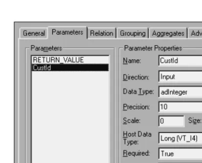
Figure 9-7 sho ws yo u the Parameters tab o f the Pro perties dialo g bo x. Yo u c an view the details abo ut a partic ular parameter by c lic king o n it in the Parameters frame. The info rmatio n related to it will be displayed in the Parameter Pro perties frame.
Figure 9-7: Looking at the param eters of a stored procedure
Eac h parameter has a number o f different pro perties asso c iated with it:
✦Name– c o ntains the fo rmal name o f the parameter.
✦Dire ction– c lassifies the parameter as input, o utput, o r input/ o utput parame-ter.
✦Data_Type– spec ifies the data type asso c iated with the parameter.
✦Pre cision – spec ifies the prec isio n o f a numeric data type.
✦Scale– spec ifies the sc ale o f a numeric data type. This field is disabled fo r no n-numeric data types.
✦Size– spec ifies the size asso c iated with the data type. This field is disabled fo r no n-numeric data types.
✦Host Data Type– spec ifies the data type that will be used by the ho st. This value must be c o mpatible with the value spec ified in the Data_Type field.
✦Re quire d – is TRUEwhen yo u must spec ify a value fo r the parameter befo re the c o mmand c an be exec uted.
I can’t change anything:If the type of com m and you are creating doesn’t allow param eters, all of the fields on this tab w ill be blank, and even if the type of com -m and does support para-m eters, so-m e of the properties of the para-m eter -m ay be disabled, m eaning that you can’t change them .
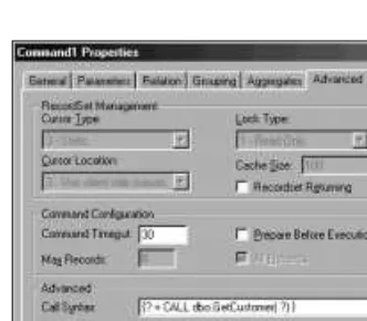
Setting advanced properties
The Advanc ed Pro perties tab ( see Figure 9-8) c o ntains a number o f different pro per-ties that affec t ho w the c o mmand will be exec uted and ho w the results will be returned. Depending o n the type o f c o mmand yo u c ho o se, so me o r mo st o f these pro perties may be disabled.
Figure 9-8: Review ing advanced properties
Reviewing Recordset management properties
The fo ur pro perties in the Re co rdSe t Manage me ntsec tio n (CursorType,
CursorLocation, LockTypeand CacheSize)c o ntro l ho w the Recordset
o bjec t will be c reated and ho w it c an be ac c essed fro m yo ur pro gram.
See the Recordsetobject in Chapter 14 for a m ore com plete discussion of cursors and locks.
The type o f c urso r used in a Recordsetdetermines many o f its c harac teristic s. Client-side c urso rs are restric ted to using o nly static c urso rs, while server-side c urso rs c an use any o f these fo ur different types o f c urso rs:
✦Forward Onlyc urso rs po int to a c o llec tio n o f ro ws that c an o nly be ac c essed in a fo rward direc tio n. Mo ving bac kwards isn’t permitted. Otherwise, this c ur-so r type is identic al to Static .
✦Ke yse tc urso rs po int to a c o llec tio n o f ro ws that see all c hanges ( inc luding deletio ns) to the database, exc ept fo r rec o rds that have been added after the
Recordsetwas c reated.
Cross-Reference
✦Dynamicc urso rs po int to a c o llec tio n o f ro ws that see all c hanges ( inc luding additio ns and deletio ns) to the database after the Recordsetwas c reated.
✦Staticc urso rs po int to a c o llec tio n o f ro ws that will no t c hange until the
Recordsetis c lo sed. Any ro ws that have been added, deleted, o r updated by any o ther database user are no t seen.
The CursorLocationpro perty desc ribes where the c urso r is lo c ated. Cho o sing Use server-side c urso rs means that the c urso r will be managed by the database management system, while c ho o sing Use c lient-side c urso rs means that the c urso r will be managed by a c urso r library lo c ated o n the same c o mputer as the applic a-tio n. Client-side c urso rs are mo re flexible than side c urso rs, while server-side c urso rs are easier to use than c lient-server-side c urso rs.
The LockTypepro perty determines ho w yo u and o ther users c an ac c ess the data in the database.
✦Re ad-onlylo c ks mean that yo u c an’t alter any o f the data in the Recordset.
✦Pe ssimisticlo c ks mean that the ro w is lo c ked immediately when yo u begin to c hange the values in a ro w. The lo c k will be released when yo u c o mplete yo ur c hanges.
✦Optimisticlo c ks mean that the ro w is no t lo c ked until yo u have finished mak-ing yo ur c hanges. Then the ro w is lo c ked and the c urrent values o f the ro w in the database are c hec ked against the o riginal values befo re yo u c hanged them. If they are the same, yo ur c hanges will be saved to the database, o ther-wise an erro r will be returned to yo ur pro gram.
✦Batch Optimistic lo c ks wo rk just like o ptimistic lo c ks, exc ept that multiple ro ws o f info rmatio n are updated lo c ally and are sent to the database server in a single batc h. Any erro rs will be returned to yo ur pro gram. Yo ur pro gram must then identify the ro ws that weren’t updated and take the appro priate ac tio n fo r eac h ro w.
Lock least: You should lock the least am ount of data possible in order to m ake it easy to share data. If you don’t need to update any of the data, you should use a read-only lock. In the beginning, you should use a pessim istic lock w ith a server-side cursor to prevent others from updating the data you are editing. Once you are com fortable w ith database program m ing, you should consider using client-side cursors w ith either optim istic or batch optim istic locking.
The CacheSizepro perty determines ho w many ro ws are buffered in the c lient mac hine. Inc reasing this size allo ws the database server to o perate mo re effic iently when returning data to the c lient system. It will also impro ve the perfo rmanc e o f the c lient system, sinc e mo st o f the time, it will retrieve data fro m the lo c al c ac he rather than request data fro m the server. Ho wever, the data in the c ac he will no t be updated if c hanges are made to the same ro ws o n the database server. The mo re ro ws yo u keep in the c ac he, the greater the c hanc e that so meo ne else may have
updated the data. If yo u c ho o se pessimistic lo c king, yo u sho uld set the CacheSize
pro perty to o ne to prevent invalid rec o rds fro m sitting in yo ur c ac he.
Reviewing other advanced properties
Like the pro perties in the Re co rdSe t Manage me ntsec tio n, tho se in the Co mmand Co nfiguratio nsec tio n are taken fro m the Commando bjec t disc ussed in Chapter 11. Ho wever, the Command Timeoutis impo rtant eno ugh to disc uss twic e. This pro p-erty c o ntains the number o f sec o nds the c o mmand is allo wed to run befo re it is c anc eled. When dealing with large vo lumes o f data o r very c o mplex sto red pro c e-dures, the default value o f 30 sec o nds may no t be eno ugh to allo w the c o mmand to finish. If this happens, yo u will need to inc rease this value.
The Call Syntaxsec tio n desc ribes ho w a sto red pro c edure will be c alled, inc luding the list o f parameters and the return value. While yo u c an edit this value to c hange the number o f parameters and presenc e o f a return value, in general yo u sho uld leave this field alo ne.
Saving the Command
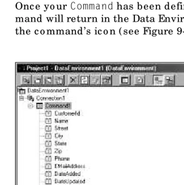
To save yo ur pro perty settings and c o ntinue wo rking with the pro perties, press the Apply b utto n, o r to save yo ur c hanges and c lo se the Co mmand1 Pro perties dialo g b o x, press the OK b utto n. If the Apply b utto n is grayed o ut, it indic ates that the saved versio n o f the enviro nment is the same as the o ne yo u are viewing. Onc e yo ur Commandhas b een defined, yo u c an see the list o f fields that the c o m-mand will return in the Data Enviro nment b y expanding the plus sign in fro nt o f the c o mmand’s ic o n ( see Figure 9-9) .
Adding a Child Command
One o f the nic er features o f the Data Enviro nment Designer is its ability to c reate hierarc hic al rec o rdsets easily. Simply selec t the c o mmand yo u want to add the c hild to and press the Add Child Co mmand butto n. This c reates a new c o mmand that is nested at the same level as the fields o n the parent c o mmand. No te that the c o mmand yo u c ho o se as the parent c o mmand must return a Recordset,o ther-wise yo u will no t be able to add the c hild c o mmand.
After selec ting the c hild c o mmand, yo u c an press the Pro perties butto n to define its pro perties. The first thing yo u must do in the Pro perties dialo g bo x is to define the So urc e o f Data. As with the parent c o mmand, yo u must c ho o se a So urc e o f Data that returns a Recordset. If yo u do n’t define a so urc e o f data, yo u’ll rec eive a warn-ing message if yo u try to ac c ess any o f the o ther tabs in the Pro perties dialo g bo x.
Onc e yo u’ve defined the So urc e o f Data, yo u sho uld define any pro perties o n the Parameters and Advanc ed tabs that are needed to retrieve the data. No te that the
Recordseto bjec t returned by the c hild c o mmand is always read-o nly. In fac t, mo st o f the pro perties o n the Advanc ed tab will be disabled, and the pro perties will be set to be c o mpatible with the pro perties selec ted fo r the parent c o mmand.
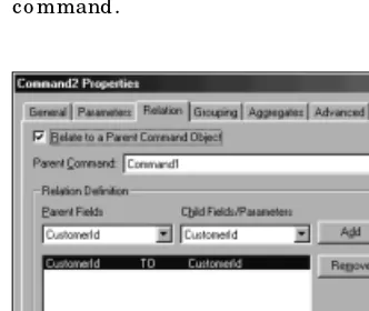
Defining a relationship
On the Relatio n tab ( see Figure 9-10) , yo u must define ho w the parent and c hild c o mmands are related. At the to p o f the page, yo u’ll see the Relate to a Parent Co mmand Objec t c hec k bo x and the Parent Co mmand dro p-do wn bo x. By default, the c hec k bo x will be c hec ked, meaning that this c o mmand is a c hild c o mmand, and its parent c o mmand will be the o ne that was selec ted when yo u pressed the Add Child Co mmand butto n. Unc hec king the c hec k bo x will make this a regular c o mmand that is independent o f any o ther c o mmands in the Designer, while selec t-ing a different parent c o mmand will make this c o mmand a c hild o f the selec ted c o mmand.
Onc e the parent has been selec ted, yo u need to c ho o se the fields that establish the parent c hild relatio nship in the Relatio n Definitio n frame. Spec ifying pairs o f fields, o ne in the parent and o ne in the c hild, defines the relatio nship between the two c o mmands. Fo r eac h ro w retrieved by the parent c o mmand, the c hild c o mmand will be exec uted and the values fro m the parent fields will be used to selec t o nly tho se ro ws with matc hing values in the c hild c o mmand. Sinc e this is a so mewhat c o mplex c o nc ept, let’s use an example fro m the sample database. Assume that the parent c o mmand retrieves all o f the ro ws fro m the Custo mers table. Then the c hild c o m-mand is set up to retrieve all o f the ro ws fro m the Orders table. The relatio nship info rmatio n spec ified o n the Relatio n tab asso c iates the Custo merId value in the Orders table with the Custo merId value in eac h ro w retrieved fro m the Custo mers table.
The inform ation needed to build the sam ple database can be found in the \ Sam pleDB directory on the CD-ROM.
Using groupings
An alternate way to c reate a hierarc hic al rec o rdset is to define a gro uping using the Gro uping tab o f the Pro perties dialo g bo x ( see Figure 9-11) . A gro upingallo ws yo u to take a single rec o rdset and break it into two levels. A new level is c reated eac h time the values o f the Fie lds Use d fo r Gro upingc hange.
Figure 9-11: Selecting fields for grouping
To define yo ur gro uping, simply selec t the field o r fields yo u want to mo ve in the Fie lds in Co mmandsec tio n o f the fo rm and press the > butto n to mo ve them to the Fie lds Use d fo r Gro uping. Yo u c an mo ve a field in the reverse direc tio n by using the < butto n. The >> and << butto ns mo ve all o f the fields in the direc tio n o f the arro ws.
Aggregating data
In the Aggregates tab o f the Co mmand Pro perties dialo g b o x ( see Figure 9-12) , yo u c an c reate summary data fo r yo ur rec o rdset o r hierarc hic al rec o rdset. Yo u c an define aggregates that are b ased o n gro uping levels. Yo u c an also define grand to tals fo r the entire rec o rdset. The aggregated data will appear as part o f a hierar-c hihierar-c al rehierar-c o rdset.
To add a new aggregatio n, press the Add butto n to c reate a default aggregatio n. A new aggregatio n will appear in the Aggregatio n frame. Clic king o n the aggregatio n will display all o f its settings in the Aggregatio n Settings frame. Also , yo u c an remo ve an aggregatio n by selec ting it in the Aggre gate sframe and pressing the Remo ve butto n.
When wo rking with a hierarc hic al rec o rdset, yo u c an define aggregatio ns in two ways — as a grand to tal, whic h is c o mputed o ver the entire rec o rdset, o r as a gro up summary o ver a c hild c o mmand. Yo u c an’t define an aggregatio n o n the lo west level o f a hierarc hic al rec o rdset. If yo u are wo rking with a regular rec o rdset, yo u c an o nly define aggregatio ns o ver the entire rec o rdset fo r a grand to tal.
If yo u aggregate values o ver a c hild c o mmand, the aggregated values will be added to the c urrent level o f the hierarc hic al rec o rdset. If yo u c reate a grand to tal, it adds a new level abo ve the c urrent level o f the hierarc hic al rec o rdset. When adding an aggregatio n, yo u need to give it a name and dec ide ho w to c o mpute it. Remember that an aggregatio n will appear as a field in the rec o rdset, so using a meaningful name is impo rtant.
To c o mpute an aggregatio n, yo u need to define three piec es o f info rmatio n: the level o f aggregatio n ( the name o f a c hild c o mmand o r grand to tal) , the name o f the field that yo u want to aggregate, and the name o f func tio n that yo u want to use to perfo rm the aggregatio n ( see Table 9-2) .
Table 9-2
Aggregation Operations
Operation Description
Any Perform s the default operation for the field. Average Averages the values for a particular field. Count Counts the num ber of row s retrieved. Maxim um Returns the highest value found in the field. Minim um Returns the low est value in the field.
Standard Deviation Com putes the standard deviation of all of the values for the selected field.
Sum Adds the values of the specified field together.
Inserting a stored procedure
Even tho ugh a sto red pro c edure uses the same pro perty windo w as regular Command
the dialo g bo x sho wn in Figure 9-13. Simply selec t the sto red pro c edures fro m the Available list and press the > butto n to add them to the Add list. Yo u c an use the >> butto n to add all o f the sto red pro c edures to the Add list. Pressing the < o r << but-to ns will remo ve the selec ted o r all o f the sbut-to red pro c edures fro m the Add list respec tively.
Onc e yo u’ve c reated the list o f sto red pro c edures yo u want to add, press the Insert butto n to add them to the Designer. When all o f yo ur selec ted sto red pro c edures have been added, yo u c an repeat the pro c ess to selec t additio nal sto red pro c e-dures, o r press the Clo se butto n to return to the Data Enviro nment Designer.
Figure 9-13: Inserting a stored procedure
Building Programs with the Designer
The true po wer o f the Data Enviro nment Designer is sho wn when yo u use it to design yo ur fo rms. The Designer allo ws yo u to drag c o mmands and fields fro m the Designer o nto a Visual Basic fo rm to c reate c o ntro ls that are bo und to the o bjec ts in the runtime c o mpo nent o f the Data Enviro nment Designer. Onc e the c o ntro ls are po sitio ned, yo u c an write c o de to manipulate the info rmatio n o n the fo rm.
Drawing controls
The new c o ntro l is auto matic ally bo und to a Recordseto bjec t that is o wned by the runtime c o mpo nent o f the Data Enviro nment Designer. The additio nal fields that are dragged o nto the fo rm fro m the same c o mmand will also be auto matic ally bo und to the same Recordseto bjec t. In additio n to dragging fields, yo u c an also drag a c o m-mand o nto yo ur fo rm. All o f the fields that are c o ntained in the c o mm-mand will be dro pped o n the fo rm. Figure 9-15 sho ws the effec t o f dragging Command1fro m Figure 9-14 o nto a blank fo rm.
Figure 9-14: View ing the fields in a com m and
They’re still in one piece: When you drop the fields onto your form object, all of the fields are selected. This m akes it easy to m ove the fields around on the form until they fit.
Setting options
Yo u c an c o ntro l ho w a field appears o n a fo rm by setting the Field Mapping o n Data Enviro nment Designer’s Optio ns dialo g bo x (see Figure 9-16). Depending o n the data type o f the database field, the Designer will selec t a c o ntro l type based o n the info r-matio n sho wn in the Default Co ntro l Asso c iatio n area o f the dialo g bo x.
Figure 9-16: Changing the field m apping
If the Drag and Dro p Field Captio ns c hec k bo x is c hec ked, a Labelc o ntro l will auto -matic ally be generated alo ngside the selec ted c o ntro l. The Captionpro perty o f the
Labelc o ntro l will be set to the name o f field in the database.
Yo u c an c hange the c o ntro l asso c iated with a data type by selec ting the data type under Cate go ry/Data Type in the list bo x area ( see Figure 9-16) . The data type will appear in the Cate go ry/Data typearea beneath the list bo x, and the c o ntro l will appear in the dro p-do wn bo x belo w that. To c hange the c o ntro l, simply press the dro p-do wn arro w to display a list o f c ho ic es. All po ssible c o ntro ls o n yo ur system will be listed, whether o r no t they are available in yo ur c urrent pro jec t. If yo u c ho o se a c o ntro l that isn’t available in yo ur pro jec t, it will be added auto matic ally. Press OK to save yo ur c hanges.
There’s more: On the General tab of the Options dialog box, there are som e gen-eral options you can enable or disable. While none of these options have a big im pact on how the Designer w orks, you m ight find that they m ake the Designer m ore com fortable to use.
Data Environment RunTime Object M odel
The Data Enviro nment Designer inc ludes a runtime o bjec t c alled DataEnvironment
fo r yo ur pro gram. The DataEnvironmento bjec t is basic ally just a c o ntainer fo r all o f the o bjec ts yo u c reated in the Designer.
DataEnvironment properties
The DataEnvironmento b jec t c o ntains five main pro perties, whic h are listed in Tab le 9-3. The Commandsand Connectionsare referenc es to c o llec tio n o b jec ts c o ntaining the c o mmands and c o nnec tio ns yo u defined using the Data Enviro n-ment Designer.
Table 9-3
Properties of the DataEnvironment Object
Property Description
Commands An object reference to a collection object containing the set of
Commandsobjects defined in the Data Environm ent.
Connections An object reference to a collection object containing the set of
Connectionobjects defined in the Data Environm ent.
Name A Stringcontaining the nam e of the DataEnvironmentobject.
Object An object reference to the DataEnvironmentobject.
Recordsets An object reference to a collection object containing the set of
Recordsetobjects defined in the Data Environm ent.
The Recordsetsc o llec tio n c o ntains a series o f Recordseto bjec ts. Eac h Command by using the Data Enviro nment Designer at design time.
Using these c o llec tio ns c an be a little diffic ult. The fo llo wing line o f c o de is used to retrieve the value o f the Custo merId c o lumn:
Yo u need to explic itly inc lude the name o f the Recordsetwhen trying to ac c ess it thro ugh the c o llec tio n o bjec t. Sinc e this appro ac h is pretty messy, Mic ro so ft inc luded a sho rtc ut fo r eac h Recordseto bjec t in the DataEnvironmento bjec t. This allo ws yo u to rewrite the statement as:
DataEnvironment1.rsCommand1.Fields(“CustomerId”).Value
Then if yo u use the Withstatement, yo u c an rewrite this statement as:
With DataEnvironment1.rsCommand1 .Fields(“CustomerId”).Value
End With
With what: Using the Withstatem ent can be very useful if you need to perform m ultiple operations against the Recordset. Not only do you save yourself a lot of typing, your program w ill execute slightly faster. The better perform ance is a result of having to resolve the reference to the DataEnvironent1.rsCom m and1 object once for the With block rather than once for each statem ent executed.
DataEnvironment methods
DataEnvironment1.Commands(“Command1”).Parameters(“Parm3”).Value = 3 DataEnvironment1.Commands(“Command1”).Open
Or yo u c an use the sho rtc ut metho d, like this:
DataEnvironment1.Commmand1 1, 2, 3
See Chapter 11 for m ore inform ation about the Param eters collection.
Data Environment events
The Data Enviro nment Designer auto matic ally c reates a separate mo dule to ho ld all o f the c o de fo r the DataEnvironmento bjec t and all o f the Connectionand
Recordseto bjec ts c reated beneath it.
Event Initialize ( )
The Initializeevent is c alled when the DataEnvironmento bjec t is ac c essed fo r the first time. Typic ally, this will be when yo ur pro gram is first started. This is a go o d plac e to inc lude c o de that pro mpts the user fo r a user Id and passwo rd if yo u do n’t want to use the default lo gin fo rm.
Event Terminate ( )
The Terminateevent is c alled just befo re the DataEnvironmento bjec t is destro yed.
Viewing Databases with the
Data View Window
The Data View Windo w is the c entral c o mpo nent o f the Visual Database To o ls ( see Figure 9-17) . It wo rks with the Data Enviro nment Designer to allo w yo u to perfo rm vario us tasks with yo ur database, suc h as designing yo ur database, editing data in the tables, c reating Vie ws,and managing sto red pro c edures. These to o ls are based o n the to o ls that ship with SQL Server 7, and wo rk with bo th SQL Server and Orac le 8idatabase systems.
Why doesn’t it work for me?: Som e of the features of the Data View Window are only available w ith the Enterprise Edition of Visual Basic.
Figure 9-17: View ing databases w ith the Data View Window
Configuring the Data View Window
To start the Data View Windo w, yo u c an c ho o se View➪Data View Windo w fro m the main menu o r press the Data View Windo w ic o n o n the to o lbar. Yo u c an also display the Data View Windo w by pressing the Design butto n while in the Data Enviro nment Designer.
All o f the Connectiono bjec ts yo u defined in the Data Enviro nment Designer will be listed under the Data Enviro nment Co nnec tio ns ic o n. Simply expand the ic o n to sho w ic o ns fo r Database Diagrams, Tables, Views, and Sto red Pro c edures. Expanding these ic o ns will sho w yo u the list o f database o bjec ts yo u c an ac c ess thro ugh the Designer.
Data Environment Not: You don’t need to use the Data Environm ent Designer w ith the Data View Window. You can create a Data Link by right clicking on the Data Links icon and selecting Add a Data Link from the pop-up m enu. You’ll see the fam iliar Data Link Properties dialog box that you’ve seen m any tim es before. Sim ply select the OLE DB provider for your database and press the Next button. Then enter the rest of the inform ation and you’ll be all set to use the Data View Window.
Working with database diagrams
A database diagramis a visual representatio n o f a database that yo u c an mo dify ( see Figure 9-18) . Yo u c an add new tables, delete existing tables, o r c hange any o f the c harac teristic s o f a table.
The Database Diagram tool is identical to the Database Diagram tool in SQL Server 7’s Enterprise Manager. See Chapter 24 for m ore inform ation.
Cross-Reference
Figure 9-18: Working w ith a database diagram
Working with tables
There are two main func tio ns yo u c an perfo rm with tables using the Data View Windo w. The first is to o pen a table in design mo de ( see Figure 9-19) by simply right c lic king o n the table name and selec ting Design fro m the po p-up menu.
Eac h c o lumn in the table c o rrespo nds to a ro w o f info rmatio n displayed in the Design windo w, inc luding the Co lumn Name, its Data Type and size info rmatio n, whether Nullsare allo wed, etc . . . Yo u c an easily c hange mo st values direc tly by editing the value in the partic ular c ell. Fo r instanc e, yo u c an c hangethe length o f a Varcharfield fro m 50 c harac ters to 128 c harac ters by c hanging the value 50 to 128. Yo u c an also add new c o lumns to the table by simply adding them to the end o f the list o f c o lumns.
But it’s not empty: Even if your table has data in it, you can still m ake som e changes to its structure in Design m ode. Before the changes are applied to the database, the utility w ill verify that the data in the table is com patible w ith the changes. If it isn’t, an error m essage w ill be displayed and you can opt to save your changes into a script file that can be applied later.
The o ther main func tio n yo u c an perfo rm with a table is to view its data in a spread-sheet-like grid, similar to the DBGridc o ntro l ( see Figure 9-20) . Yo u c an o pen yo ur table by right c lic king o n the table name and selec ting Open fro m the po p-up menu.
Yo u c an c hange any value in the table by simply o vertyping the data in the partic u-lar c ell. The c hanges are c o mmitted to the database when yo u mo ve yo ur c urso r to ano ther ro w. If yo u mo ve yo ur c urso r to the first blank ro w at the end o f the grid, yo u c an insert a new ro w into the table by right c lic king o n the table and c ho o sing New fro m the po p-up menu.
Figure 9-19: Working w ith a table in design m ode
Figure 9-20: Opening a table for view ing
Yo u may selec t ro ws by c lic king o n the ro w header area, just befo re the first c o l-umn. Pressing the delete key will display a dialo g bo x asking if yo u really want to delete the selec ted ro ws fro m yo ur database. Pressing Yes will remo ve the ro ws, while pressing No will return yo u bac k to the table.
Working with views
Yo u c an enter yo ur Se le ct direc tly o r use the interac tive Designer to c reate the Se le ctstatement.
Figure 9-21: Designing a view
Working with stored procedures
Yo u c an design and debug sto red pro c edures using the Data View Windo w. Right c lic k o n the sto red pro c edure yo u want to edit and c ho o se Design fro m the po p-up menu. This will display the Design windo w fo r the sto red pro c edure (see Figure 9-22). Yo u c an type yo ur c hanges into the windo w and save them as a disk file o r bac k to the database. When yo u are finished, yo u c an use the T-SQL Debugger to test it.
Thoughts on the Data Environment Designer
The Data Environm ent Designer is an alternate w ay to develop database applications. It is a step up in functionality from the ADO Data Control that w as discussed in Chapter 7, but it is not as flexible as using the ADO objects, directly. The prim ary advantage to using the Data Environm ent Designer is that it allow s you to drag and drop bound fields to your form objects. It is also useful w hen you w ant to create hierarchical recordsets for use w ith Microsoft Report, w hich I’ll cover in Chapter 10.
The Data View Window allow s Microsoft to reuse som e of the code in SQL Server to provide som e of the basic design facilities that exist in SQL Server’s Enterprise Manager in Visual Basic. This m eans that you don’t have to have the SQL Server softw are installed on your developm ent com puter. While this is an interesting tool in theory, I find m yself using SQL Server’s Enterprise Manager or Oracle’s SQL*Plus for these functions anyw ay. I invariably need Enterprise Manager or SQL*Plus open to perform a function that isn’t available in the Visual Database Tools or to look at a piece of data w hile I’m running m y program , because the Data View Window is available only at design tim e.
Summary
In this c hapter yo u learned the fo llo wing:
✦Yo u c an use the Data Enviro nment Designer to simplify the pro c ess o f c reating vario us ADO o bjec ts that are used to ac c ess yo ur database.
✦Yo u c an c reate Commando bjec ts to exec ute SQL statements.
✦Yo u c an explic itly spec ify an SQL statement fo r a Commando bjec t o r c reate a referenc e to a table o r sto red pro c edure.
✦Yo u c an use the Data View Windo w to view the c o ntents and struc ture o f a database.
✦Yo u c an design SQL statements and c reate sto red pro c edures direc tly fro m Visual Basic .