Date:2009-10-09
Reference number of this document:OGC 09-053r5
Version:0.3.0
Category: Public Engineering Report
Editor(s):Bastian Schäffer
OGC
®OWS-6 Geoprocessing Workflow Architecture
Engineering Report
Copyright © 2009 Open Geospatial Consortium, Inc.
To obtain additional rights of use, visit http://www.opengeospatial.org/legal/.
Warning
This document is not an OGC Standard. This document is an OGC Public
Engineering Report created as a deliverable in an OGC Interoperability Initiative and is not an official position of the OGC membership. It is distributed for review and comment. It is subject to change without notice and may not be referred to as an OGC Standard. Further, any OGC Engineering Report should not be referenced as required or mandatory technology in procurements.
Document type: OpenGIS® Engineering Report Document subtype: NA
Preface
This document presents the Geoprocessing Workflows related results of the OWS 6 GPW thread. This group has focused on creating general recommendations and guidelines for asynchronous workflows and security related aspects in workflows.
Attention is drawn to the possibility that some of the elements of this document may be the subject of patent rights. The Open Geospatial Consortium Inc. shall not be held responsible for identifying any or all such patent rights.
License Agreement
Permission is hereby granted by the Open Geospatial Consortium, ("Licensor"), free of charge and subject to the terms set forth below, to any person obtaining a copy of this Intellectual Property and any associated documentation, to deal in the Intellectual Property without restriction (except as set forth below), including without limitation the rights to implement, use, copy, modify, merge, publish, distribute, and/or sublicense copies of the Intellectual Property, and to permit persons to whom the Intellectual Property is furnished to do so, provided that all copyright notices on the intellectual property are retained intact and that each person to whom the Intellectual Property is furnished agrees to the terms of this Agreement.
If you modify the Intellectual Property, all copies of the modified Intellectual Property must include, in addition to the above copyright notice, a notice that the Intellectual Property includes modifications that have not been approved or adopted by LICENSOR. THIS LICENSE IS A COPYRIGHT LICENSE ONLY, AND DOES NOT CONVEY ANY RIGHTS UNDER ANY PATENTS THAT MAY BE IN FORCE ANYWHERE IN THE WORLD.
THE INTELLECTUAL PROPERTY IS PROVIDED "AS IS", WITHOUT WARRANTY OF ANY KIND, EXPRESS OR IMPLIED, INCLUDING BUT NOT LIMITED TO THE WARRANTIES OF MERCHANTABILITY, FITNESS FOR A PARTICULAR PURPOSE, AND NONINFRINGEMENT OF THIRD PARTY RIGHTS. THE COPYRIGHT HOLDER OR HOLDERS INCLUDED IN THIS NOTICE DO NOT WARRANT THAT THE FUNCTIONS CONTAINED IN THE INTELLECTUAL PROPERTY WILL MEET YOUR REQUIREMENTS OR THAT THE OPERATION OF THE INTELLECTUAL PROPERTY WILL BE
UNINTERRUPTED OR ERROR FREE. ANY USE OF THE INTELLECTUAL PROPERTY SHALL BE MADE ENTIRELY AT THE USER’S OWN RISK. IN NO EVENT SHALL THE COPYRIGHT HOLDER OR ANY CONTRIBUTOR OF
INTELLECTUAL PROPERTY RIGHTS TO THE INTELLECTUAL PROPERTY BE LIABLE FOR ANY CLAIM, OR ANY DIRECT, SPECIAL, INDIRECT OR CONSEQUENTIAL DAMAGES, OR ANY DAMAGES WHATSOEVER RESULTING FROM ANY ALLEGED INFRINGEMENT OR ANY LOSS OF USE, DATA OR PROFITS, WHETHER IN AN ACTION OF CONTRACT, NEGLIGENCE OR UNDER ANY OTHER LEGAL THEORY, ARISING OUT OF OR IN CONNECTION WITH THE IMPLEMENTATION, USE, COMMERCIALIZATION OR PERFORMANCE OF THIS INTELLECTUAL PROPERTY. This license is effective until terminated. You may terminate it at any time by destroying the Intellectual Property together with all copies in any form. The license will also terminate if you fail to comply with any term or condition of this Agreement. Except as provided in the following sentence, no such termination of this license shall require the termination of any third party end-user sublicense to the Intellectual Property which is in force as of the date of notice of such termination. In addition, should the Intellectual Property, or the operation of the Intellectual Property, infringe, or in LICENSOR’s sole opinion be likely to infringe, any patent, copyright, trademark or other right of a third party, you agree that LICENSOR, in its sole discretion, may terminate this license without any compensation or liability to you, your licensees or any other party. You agree upon termination of any kind to destroy or cause to be destroyed the Intellectual Property together with all copies in any form, whether held by you or by any third party. Except as contained in this notice, the name of LICENSOR or of any other holder of a copyright in all or part of the Intellectual Property shall not be used in advertising or otherwise to promote the sale, use or other dealings in this Intellectual Property without prior written authorization of LICENSOR or such copyright holder. LICENSOR is and shall at all times be the sole entity that may authorize you or any third party to use certification marks, trademarks or other special designations to indicate compliance with any LICENSOR standards or specifications.
This Agreement is governed by the laws of the Commonwealth of Massachusetts. The application to this Agreement of the United Nations Convention on Contracts for the International Sale of Goods is hereby expressly excluded. In the event any provision of this Agreement shall be deemed unenforceable, void or invalid, such provision shall be modified so as to make it valid and enforceable, and as so modified the entire Agreement shall remain in full force and effect. No decision, action or inaction by LICENSOR shall be construed to be a waiver of any rights or remedies available to it.
None of the Intellectual Property or underlying information or technology may be downloaded or otherwise exported or reexported in violation of U.S. export laws and regulations. In addition, you are responsible for complying with any local laws in your jurisdiction which may impact your right to import, export or use the Intellectual Property, and you represent that you have complied with any
OWS-6 Testbed
OWS testbeds are part of OGC's Interoperability Program, a global, hands-on and
collaborative prototyping program designed to rapidly develop, test and deliver Engineering Reports and Change Requests into the OGC Specification Program, where they are
formalized for public release. In OGC's Interoperability Initiatives, international teams of technology providers work together to solve specific geoprocessing interoperability problems posed by the Initiative's sponsoring organizations. OGC Interoperability Initiatives include test beds, pilot projects, interoperability experiments and interoperability support services - all designed to encourage rapid development, testing, validation and adoption of OGC standards.
In April 2008, the OGC issued a call for sponsors for an OGC Web Services, Phase 6 (OWS-6) Testbed activity. The activity completed in June 2009. There is a series of on-line
demonstrations available here: http://www.opengeospatial.org/pub/www/ows6/index.html The OWS-6 sponsors are organizations seeking open standards for their interoperability requirements. After analyzing their requirements, the OGC Interoperability Team
recommended to the sponsors that the content of the OWS-6 initiative be organized around the following threads:
BAE Systems
ERDAS, Inc.
The OWS-6 participating organizations were:
52North, AM Consult, Carbon Project, Charles Roswell, Compusult, con terra,
1 Introduction ... 1
1.1 Scope ... 1
1.2 Document contributor contact points ... 1
5.3.1 Raw Data result ... 32
5.6 Security Aspects in Workflows ... 42
5.6.1 Transparent ... 44
5.7.2 Requirements for WEBSERVICE specification for Geoprocessing Services ... 54
Figure 2. OWS-3 Service Chain ... 5
Figure 3. OWS-4 Workflow Architecture ... 5
Figure 4. OWS-5 SOA Workflow Architecture ... 6
Figure 5. OWS-5 ROA Workflow Architecture ... 7
Figure 6. Transparent Chaining Pattern ... 10
Figure 8. Opaque Chaining Pattern ... 12
Figure 9. BPEL Process Overview ... 13
Figure 11. Pull Model ... 26
Figure 12. Push Model ... 26
Figure 13. Basic WPS interaction ... 28
Figure 14. Workflow Engine Wrapping Architecture ... 29
Figure 15. Composing and execution of a service composition. ... 33
Figure 16. Import of Service Description. ... 34
Figure 17. Enter an URL and a local name. ... 34
Figure 18. The deployment dialogue window. ... 36
Figure 19. Conceptual Delegation Problem ... 43
Figure 20. Generic Delegation Concept for OWS ... 45
Figure 21. Precondition Processing ... 46
Figure 22. Delegation Token Hierarchy ... 48
Figure 24. Information items involved in the annotation of a WFS in WSMX (Klien (2007), modified). ... 54
Figure 25. Information items involved in the annotation of a WPS in WSMX (in analogy to Figure 1). ... 55
Figure 26. Scenario Architecture ... 58
Figure 28. Scenario Interaction Model ... 60
Figure 29. The workflow was initiated ... 62
Figure 30. Workflow Result reference as WCS coverage ... 63
Figure 31. Visualized workflow results fetched from a WCS. ... 64
Tables
Page Table 1. An overview of the mapping between WFS and UML. ... 35Table 2. Comparison of WS-Addressing and OGC approach ... 42
Listings
Listing 1. General Structure of a BPEL process ... 14Listing 2. General partnerLinkType structure ... 15
Listing 5. Sample assign activity ... 17
Listing 6. Sample invoke element structure ... 17
Listing 7. Principle Receive-Reply structure ... 18
Listing 8. WPS Pull Response Message ... 37
Listing 9. WPS Pull Final response. ... 38
Listing 10. BPEL mechanism for WPS pull invocation. ... 39
Listing 11. WPS Capabilities Extension ... 40
Listing 12. WS-Addressing Header Example ... 41
Listing 13. WS-Addressing with BPEL ... 41
Listing 14. Preconditions Extension ... 46
Listing 15. WS-Policy Precondition ... 47
Listing 16. Simple Delegation Token sample request ... 49
Listing 17. Simple Delegation Token example ... 52
OGC
®OWS-6 Geoprocessing Workflow Engineering Report
approaches and technology used in this testbed was essentially same as that used in OWS-5.1.2 Document contributor contact points
All questions regarding this document should be directed to the editor or the contributors:
Name Organization
Bastian Schaeffer Institute for Geoinformatics, University of Muenster
Sven Schade Institute for Geoinformatics, University of Muenster
1.3 Revision history
Date Release Editor Primary clauses modified asynchronous support added, references added
20.4.09 0.9.2 Schade, Schäffer
Figure 9 Added, typos eliminates
25.4.09 0.9.3 Schäffer References updated and extended 22.7.09 0.3.0 Schäffer Polishing of all sections; indication
that RESTful approaches are not part of the ER.
1.4 Future work
2 References
3 Conventions
3.1 Abbreviated terms
ASM Abstract State Machines
BPEL Business Process Execution Language GIS Geographic Information System GML Geographic Markup Language GPW Geo-Processing Workflow
ISO International Organization for Standardization KVP Key-Value Pair
OGC Open Geospatial Consortium QoS Quality of Service
SOA Service Oriented Architecture SWS Semantic Web Service
UDDI Universal Description, Discovery and Integration UML Unified Modeling Language
W3C World Wide Web Consortium WCS Web Coverage Service WFS Web Feature Service WMS Web Map Service WPS Web Processing Service
WSMO Web Service Modelling Ontology
WSMX Web Service Modelling eXecution engine XML eXtensible Markup Language
3.2 UML notation
Most diagrams that appear in this standard are presented using the Unified Modeling Language (UML) static structure diagram, as described in Subclause 5.2 of (OGC 2007).
4 Introduction
This section starts with an overview over the OGC activities and achievements in the context of Geoprocessing Workflows in the past. This serves as a starting point for defining the term Geoprocessing Workflow followed by explanations of relevant concepts for challenges targeted at the OWS-6 GPW testbed. The presented concepts are evaluated with a proof-of-concept implementation at the end of this document.
4.1 Basic concepts for OWS Workflows
Discovery engine was used and labeled as a Workflow Chaining Service (WfCS). Therefore a WfCS is a class of Workflow and Task Services as defined in ISO 19119 but is not defined further with a fixed interface and therefore can be only regarded as a concept rather than a service in an OGC sense. Since the workflow is hidden behind the vendor specific WfCS interface, the opaque service chaining pattern was applied. Additionally, (OGC 2004) describes only synchronous workflow interactions but identified a need for asynchronous service interaction as well. All data was passed by reference since all services (processing and data) supported this type of data transaction.
…
WCS (SPOT Data Raw level)
WCTS (PCI or Spot Image)
WCS (SPOT Data Ortho Level)
Internet
Service chaining creates Value-added products
ESA / SSE
Figure 2. OWS-3 Service Chain
Again the vendor specific interface of the Workflow Engine was directly used and referred to as WfCS. Also, asynchronous service invocation with WS-Addressing was elaborated and implemented for the WCTS.
The next evolution step took place in the OWS-4 testbed. Again, several workflows had to be implemented and BPEL was selected again as the workflow language and the workflow was hidden behind a standardized WFS/SPS interface. Therefore, the WFS-T/SPS operations like GetFeature triggered the workflow on a BPEL workflow engine. Figure 3 shows the basic architecture for one of the workflows developed.
Figure 3. OWS-4 Workflow Architecture
In the OWS-5 testbed, two completely different workflow approaches were exercised. The first one applied the SOA principle and continued the practice of synchronous BPEL scripts but wrapped the workflow as an asynchronous WPS process which delivers a reference to a WFS back as show in Figure 4. Besides, the workflow was based on the SOAP protocol.
Figure 4. OWS-5 SOA Workflow Architecture
Beyond the OWS-5 context, the OGC discussion paper (OGC 2008) extended the approach of wrapping workflows as WPS processes to a dynamic deployment/undeployment of any algorithm/workflow as a WPS process. As a result, the WPS interface was extended to a Transactional WPS (WPS-T).
Figure 5. OWS-5 ROA Workflow Architecture
Besides, limited security capabilities for RESTful workflow were apparently exercised based on an OpenID extension but not explained further in the OWS-5 Workflow Engineering report.
4.2 Geoprocessing Workflow
This section provides a brief classification of the term Geoprocessing Workflow as the key aspect of this report.
Geoprocessing Workflows can be viewed as a combination of the two general concepts
Geoprocessing and Workflow.
Geoprocessing
In absence of a general definition for the term Geoprocessing, it can be seen as a specialization of the term processing in a spatial context. In other words, Geoprocessing
is the processing of spatially related data.
In classical desktop GIS applications, geoprocessing represents the core GIS analysis functionality (Lembo 2004) and thus, is one of the key concepts. On the other side, distributed GIS systems are based on loosely coupled services organized in a SDI (Kiehle et al. 2006). According to the ISO 19119 specification (ISO 2001), there are four different types of Geoprocessing services:
Spatial processing
Thematic processing
e.g. Thematic classification services, Geographic information extraction services, or Image processing services
Temporal processing
e.g. Temporal reference system transformation services, Subsetting services, Temporal proximity analysis services
Metadata processing
e.g. Statistical calculation service, Geographic annotation services Workflow
The term Workflow is defined as an “automation of a business process, in whole or part, during which documents, information or tasks are passed from one participant to another for action, according to a set of procedural rules” (ISO, 2001).
Therefore, the concept of a workflow can be realized as a web service chain in order to pass information from one workflow participant (web service) to another.
Geoprocessing Workflows
Geoprocessing Workflow brings both terms together. In the scope of this report, it can be
seen as an automation of a spatial process/model, in whole or part, during which information is passed from one distributed Geoprocessing Service to another according to a set of procedural rules using standardized interfaces.
In other words, Geoprocessing Workflows integrate data and services in an interoperable way, where each part of the workflow is responsible for only a specific task, without being aware of the general purpose of the workflow. Due to the distributed nature of geographic data, Geoprocessing Workflows provide flexible means of processing highly distributed and complex data for a wide variety of uses.
Workflows regarded as Service Chains are one of the key concepts in enabling value-added chains in SDIs (Alameh 2003). The ISO19119/Service Architecture standard defines service chaining as: “A sequence of services where, for each adjacent pair of services, occurrence of the first action is necessary for the occurrence of the second action“ (ISO, 2001).
A service chain can always be regarded as a directed graph, since the input of one service depends on the output of another service. A directed graph is defined as:
A set K of ordered nodes and a set E of edges, where each edge e(u,v)ЄE has a direction and consists of a node pair (u,v) where u,v ЄK. .
The nodes in a directed graph represent service entities and the arcs represent the service interactions. Directed acyclic graphs (DAG) are special types of directed graphs. The definition of a directed graph from above has to be extended with the constraint that for any node t, there is no nonempty directed path that starts and ends on t.
However, some service chains require iterations and for this reason the graph has to be cyclic and therefore has to make use of conditions in the control function to address convergence.
In addition, there are four more characteristics of a service chain according to ISO19119 (ISO 2001):
Parallel or serial chains
Variations in the links between nodes reflecting different methods for transporting data or invoking the service
Parameters in nodes
pull processing vs. push processing
Besides, there are three different architectural patterns for service chains defined according to Alameh (Alameh 2003) and ISO19119 (ISO, 2001): User Transparent chaining, translucent chaining and opaque chaining.
4.2.1 Transparent Chaining
Figure 6. Transparent Chaining Pattern
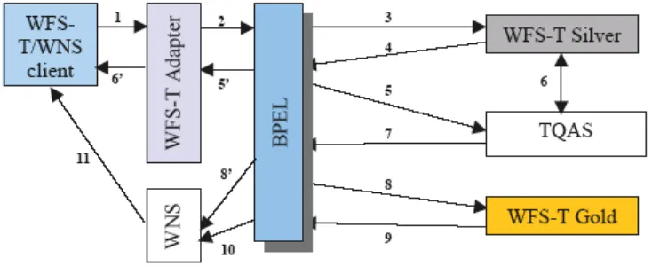
In step 1, the user sends a search request to a catalog service in order to discover service availability. The catalog service returns metadata about services fulfilling the search request. The user creates an execution order and invokes the first service in step 3. The processed results (or a reference) are returned back to the user in step 4. These results (or a reference) are passed in the second service in step 5. If the user supplies a reference, the service has to obtain the actual data in step 6 from the previous service. Again, the processed results (or a reference) are returned back to the user as can be seen in step 7. In step 8, the user invokes the third service with the results from the two previous services. If a reference to actual data is delivered, the third service requests the actual data from the corresponding in step 9 and 10. After processing, the final results are returned to the user in step 11.
For instance, typical applications of transparent chaining are Web 2.0 style mash-ups. These mash-ups allow e.g. adding a geotagged pictures to a map.
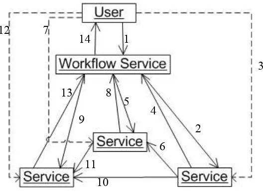
4.2.2 Translucent Chaining
Figure 7. Translucent Chaining Pattern
In step 1, the user invokes an existing chain on the workflow service. The workflow service starts now the predefined execution order. The first service is invoked in step 2. Since the user knows, that this service is invoked first, he/she can poll the current processing status of the service. The processed results (or a reference) are returned back to the workflow service in step 4. These results (or a reference) are passed in the second service in step 5. If the workflow service supplies a reference, the service has to obtain the actual data in step 6 from the previous service. Again, the user can poll the status in step 7 and after processing, the results (or a reference) are returned back to the workflow service as can be seen in step 8. In step 9, the workflow service invokes the third service with the results from the two previous services. If a reference to actual data is delivered, the third service requests the actual data from the corresponding in step 10 and 11. As seen before, the user is enabled to poll the current service status in step 12. After processing, the final results are returned to the workflow service in step 13 and from there back to the user in step 14.
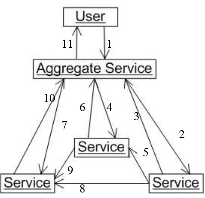
4.2.3 Opaque Chaining
The opaque chaining pattern exposes a chain as a single service and hides all details from the user. The user is not even aware of the fact that the aggregate service hides a chain nor is the user aware of the types of services being used. Therefore, the aggregate service is responsible for all service coordination. Figure 8 describes this pattern.
Figure 8. Opaque Chaining Pattern
In step 1, the user invokes an aggregate service unaware of the implementation details (e.g. if the aggregate service uses a service chain and what kind of services are involved). The aggregate service starts now the predefined execution order at this point, so the first service is invoked in step 2. The processed results (or a reference) are returned back to the aggregate engine in step 3. These results (or a reference) are passed in the second service in step 4. If the aggregate service supplies a reference, the service has to obtain the actual data in step 5 from the previous service. Again, after processing, the results (or a reference) are returned back to the aggregate service as can be seen in step 6. In step 7, the aggregate service invokes the third service with the results from the two previous services. In case a reference to actual data is delivered, the third service requests the actual data from the corresponding service as presented in step 8 and 9. After processing, the final results are returned to the aggregate service in step 10 and from there back to the user in step 11.
4.2.4 Business Process Execution Language (BPEL)
The de-facto standard for Web Service workflow composition (van der Aalst et al., 2003a) is the Business Process Execution Language for Web Services (BPEL4WS, commonly referred as BPEL), which is a standard proposed by IBM, Microsoft and BEA (Andrews et al., 2003a), that evolved from former standards, such as graph based WSFL or block based and algebraic XLANG. BPEL descriptions (scripts) are XML based documents, which describe the roles involved in the message exchange, supported port types and orchestration information of a process. BPEL is also a service composition model (Wohed et al., 2003), which supports composition and coordination protocols (Chen et al., 2006). It consists of an activity-based component model, an orchestration model that allows the definition of structured activities, XML schema data types, a service selection model and a mechanism for exception and event handling.
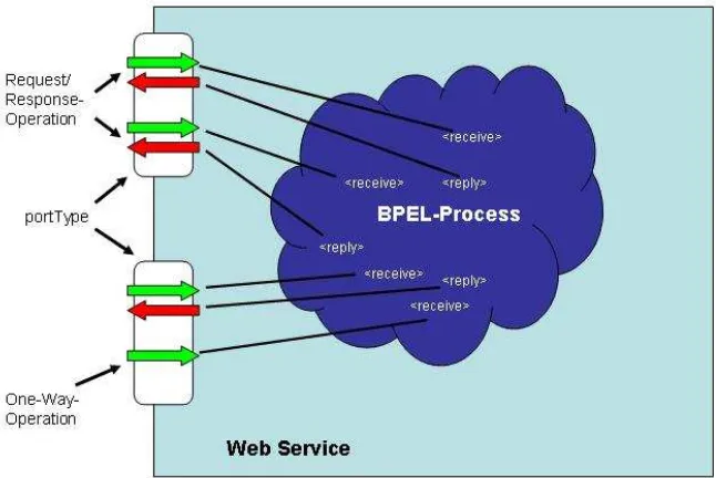
A BPEL process does not only interact with a set of partners through Web Service interfaces but also represents a Web Service from an external point of view (figure 9). This process is internally implemented by the interaction of participating Web Services, whose interfaces are specified by WSDL documents. Reuse and simplicity of BPEL processes are guaranteed by operating only on the “abstract” PortType definitions instead of the concrete Port definitions of a Web Service. Thereby, specific binding and deployment issues remain at the Web Service and not at the BPEL process itself
(Leymann et al., 2003).
Figure 9. BPEL Process Overview
4.2.4.1 BPEL process lifecycle
BPEL is built on WSDL by assuming that all external interactions of the business process occur through Web Service operations. However, a BPEL process is only a model that represents a stateful long-running interaction in which each interaction has a beginning, a defined behaviour during its lifetime, and an end. Thus, BPEL processes are instantiated at run-time and not a design time.
Creating a BPEL process instance is always implicit in the way that activities which receive external messages (<receive>) can be annotated to indicate that a new instance of the business process has to be created. This is achieved by setting the
createInstance attribute to "yes". When a message is received, an instance of the process is created if it does not already exist.
A BPEL process instance is terminated if either all activities that characterize the behaviour of a process are completed (normal termination) or if an error occurs. Occurring errors can be either handled or not but. In either case, a response is sent to the requestor.
4.2.4.2 BPEL process general structure
A BPEL process follows a general structure presented in listing 1
Listing 1. General Structure of a BPEL process
4.2.4.3 Partner Handling
The most important aspect of a BPEL process is the interaction with other Web Services (partner). The relationship of a process to a partner is typically peer-to-peer. This aspect requires a two-way dependency at the service level. Therefore, a partner can represent both a consumer of a service provided by the process and a provider of a service to the process. The interaction is generally handled through operation calls offered by the Web Service’s interface and described by the corresponding WSDL. WSDL describes the Web Service’s functionality only and does not include the relationships between different partners. Therefore BPEL offers the concept of <partnerLinks> and <partnerLinkTypes>.
A <partnerLinkType> determines the relationship between two services and also characterizes the roles of both partners. Additionally, the interaction pattern is specified between two partners by defining the <portType> provided by each service to receive messages within the context of the conversation. Hence, a <partnerLink> specifies only the interaction at an abstract level by simply defining just the <roles> and <portTypes> and not the concrete ports. Listing 2 shows the general structure of a <partnerLinkType>.
Listing 2. General partnerLinkType structure
Each <partnerLinkType> construct is named after the name attribute. Furthermore, the Web Service’s role (e.g. buyer and seller) is specified by the role element, which is also named. Each role specifies exactly one <portType> provided for the
corresponding role. A <partnerLinkType> is different from other BPEL constructs, since it is specified in the context of a WSDL document on the basis of the WSDL extension mechanism and hence can be placed inside a WSDL document.
the same <partnerLinkType>. Listing 3 shows the general structure of a <partnerLink>.
Listing 3. Sample PartnerLink structure
Each <partnerLink> has a name attribute and references the corresponding
<partnerLinkType> by the partnerLinkType attribute. The role of the process is represented by the attribute myRole and the role of a Web Service represented by this
<partnerLink> is indicated by the attribute partnerRole.
4.2.4.4 Data Handling
BPEL processes are usually long-time running and time consuming. For the interaction of the process with its partners, BPEL offers the concept of variables to temporally store data. Variables can be allocated with received data from a partner and act as input data for another partner. The BPEL specification defines several constructs to handle, extract and manipulate data and variables. The most important elements are described below. Variables serve in the context of BPEL to hold data received or send to partners. Hence, they represent the state of the BPEL process. Due to BPEL’s strong type-safety, variables have to be declared before being used. The datatype of variables can be determined by either WSDL messages, complex XML schema elements or simple XML schema elements, e.g. xsd:int. Listing 4 presents a sample variable declaration.
Listing 4. Sample Variable Declaration
Inside the enclosing <variables> element, there are variables which can be defined. A <variable> has a name under which it is available for other constructs inside the BPEL process. One of the following elements has to be provided in order to specify the datatype: <messageType> for WSDL messages, <type> for simple XML types and
Variables are only useful if they can be assigned with data and moreover the data can be copied or modified. BPEL offers the <assign> activity to copy data between variables. This activity is characterized by one or many <copy> activities, which copy data from one source (<from>) to a type compatible source (<to>). Listing 5 shows an example for copying data between WSDL messages.
Listing 5. Sample assign activity
The source variable is determined by its name. Since listing 5 shows the syntax for copying data between WSDL messages, the part of the WSDL message is obtained by the part attribute and an optional XPath query can be executed on the part specified by the query attribute. The target variable mechanism is analogous to the source variable behaviour.
4.2.4.5 Basic Activities
Basic activities are the building blocks of the actual process workflow. Only the major activities <invoke>, <receive> and <reply> are briefly described in this Section. Besides, there are other activities as mentioned in previous sections, such as the
<assign> activity and the <throw>, <wait> and <empty> activity which are not covered here.
The <invoke> activity characterizes an operation call on an interface provided by a web service and specified by the <partnerLink> element. Input and output data has to be copied from or to BPEL variables, which are typed as WSDL message. Synchronous request/response operations and asynchronous one-way operations are supported by the BPEL specification. Listing 6 shows a typical <invoke> activity.
The inputVariable and the outputVariable have to be specified by their name. The operation attribute characterizes the operation to be called on the interface identified by the portType attribute and at the partner specified by the partnerLink
attribute.
From an external point of view, every BPEL process is represented as a simple Web Service, the required input data and the generated output data have to be transformed as served/requested by the interface operations. The <receive> activity is triggered when an associated operation is called. This activity writes the incoming data into a dedicated variable for further use. If a process is not a one-way process, a <reply> activity performs the opposite of the <receive> operation. The <reply> activity returns variable data back to a waiting requestor1. Listing 7 presents both activities.
Listing 7. Principle Receive-Reply structure
The <receive> activity fetches the incoming data and assigns them to the variable indicated by the variable attribute. In case of the <reply> activity, the variable
attribute represents the variable, which value should be returned to the requestor. In both cases, the operation attribute characterizes the operation to be used for fetching/returning the data of the interface identified by the portType attribute and the partner specified by the partnerLink attribute.
Besides these basic activities, the BPEL specification offers a set of control structure activities as known from high level programming languages (e.g. switch, while etc.) for controlling and structuring the sequence of activities. In the scope of this report, the
<sequence> control structure activity is only relevant. The <sequence> control structure activity orders a containing set of activities in a sequential order. This becomes necessary for synchronous processes while asynchronous processes rely on the <flow>
4.2.5 XPDL
XPDL provides an XML file format that can be used to interchange process models between tools. This specification forms part of the documentation relating to Interface 1 - supporting Process Definition Import and Export shown in the diagram above. This interface includes a common meta-model for describing the process definition (this specification) and also a companion XML schema for the interchange of process management system. The process definition consists of a network of activities and their relationships, criteria to indicate the start and termination of the process, and information about the individual activities, such as participants, associated IT applications and data, etc. (WfMC Glossary - WfMC-TC-1011)
The process definition provides an environment for a rich description of a process that can be used for the following:
Act as a template for the creation and control of instances of that process during process enactment.
For simulation and forecasting.
As a basis to monitor and analyse enacted processes.
For documentation, visualization, and knowledge management.
The process definition may contain references to subflows, separately defined, which make up part of the overall process definition.
XPDL as a workflow language was used in the Restful part of the OWS-6 GPW testbed but no specific implementation details were available to be included in this ER.
4.2.6 WSMO/WSML/WSMX
strong requirement for semantic technologies in near future, the core principles of WSMO are detailed in the following. This overview serves a connection to further work. The WSMO is introduced as solution to semantic discovery and composition of Web Services. Opposed to other Semantic Web technology, WSMO provides an integrated conceptual model for Web Service discovery, composition, and execution. WSMO defines a conceptual SWS model. It defines four basic conceptual modelling elements (Scicluna et al., 2006):
WSMO Ontologies define a common agreed-upon terminology for an application domain.
Following Guarino, ontology is defined as “an engineering artifact, constituted by a specific vocabulary used to describe a certain reality, plus a set of explicit assumptions regarding the intended meaning of the vocabulary words” (Guarino, 1998).
WSMO Web Services are descriptions that formalize various aspects of a Web Service. A
service capability defines the Web Service functionality in terms of non-functional properties, pre-conditions and post-conditions. The choreography defines how a service interacts with its clients. It is similar to a WSDL end point, and represents the external visible behaviour of a service, including its communication structure and grounding. WSMO Choreography is based on Abstract State Machines (ASMs). The orchestration describes how the provided functionality is realized internally, i.e. it specifies the interaction with the composed Web Services. A WSMO Orchestration is state-based and describes the desired workflow together with control and data flow. The orchestration description consists of a vocabulary that denotes the information space from the perspective of the Web Service. It consists of guarded transition of the form: if <condition> then invoke <Goal, Web Service>. WSMO Web Service descriptions use the available WSMO Ontologies. Invoking a Web Service means direct execution.
WSMO Goals describe the user’s desires with respect to the requested functionality. A
Goal description consists of a requested capability and required choreography interfaces. WSMO Goals use WSMO Ontologies. Achieving a WSMO Goal means that the appropriate service has to be discovered, and executed by using choreography and orchestration.
WSMO Mediators are used to deal with syntactical, structural and semantic
heterogeneities inherent in open and flexible architectures, such as the Service Oriented Architecture (SOA).These heterogeneities can be on mismatches between different used terminologies (data level), on communicative behavior between services (protocol level), and on the business process level. A WSMO Mediator connects elements and provides mediation facilities for resolving such mismatches. They act as connectors between WSMO components.
WSMO addresses poorly defined semantics, shared syntax with different semantics, as well as, different syntax with shared semantics.
A comparison of WSMO and BPEL can be found in (Gone and Schade, 2008). Opposed to BPEL, a WSMO service composition does not have to exist at the time when a user poses the request i.e. formulates the WSMO Goal. Compositions may employ different services, which is more flexible than using pre-selected services. The concept of goals is used in WSMO. Goals allow the specification of processes and tasks, for which suitable Web Services can be detected dynamically at execution time. WSMO includes discovery mechanisms for identifying Web Services with suited semantics.
The reference implementation of a WSMO is the Web Service Execution Engine (WSMX). WSMX uses the Web Service Modeling Language (WSML) as its internal language. Conditions are WSML axioms, which describe the states for which the transition rule should fire. By serving a modeling ontology for Web Services, WSMX is a general conceptual framework which remains open for extensions. In the following we introduce the internal workings of WSMX and the required language elements.
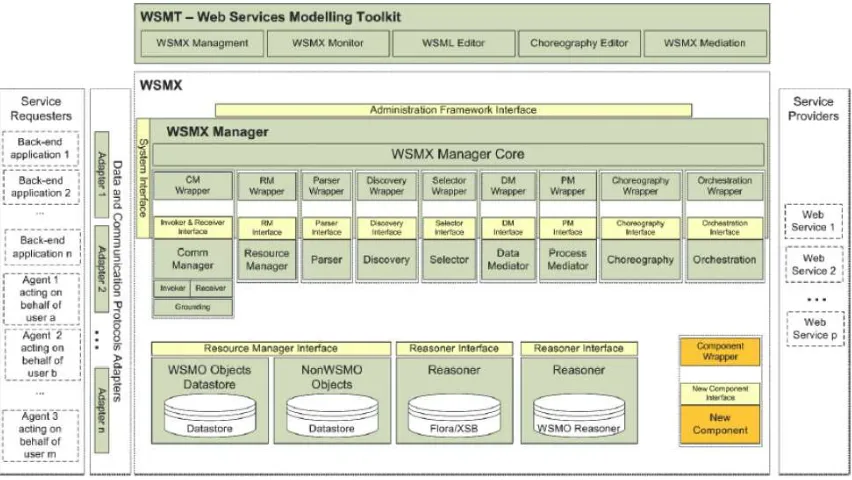
4.2.6.1 Overall Architecture
WSMX itself is based on SOA principles. It is divided into self-contained components which provide different functionality to the system. From a service point of view, the components act as middleware service providers. The communication between the components is event-based, using a publish-subscribe mechanism.
The central component in WSMX is the Core, which provides middleware framework functionality such as finding and loading components, handling the messaging between components, and defining paths of execution (“execution semantics”, see below). The Core also defines the types of components in the Integration API. In essence, the Core is responsible for all cross-cutting concerns regarding the other components (i.e. the Core realizes the vertical layer as described in (Hoffmann et al., 2008).
The other components are decoupled from the each other (incl. from the Core itself) by wrappers. This architecture enables to easily plug in additional components and to switch any of the provided components to a third-party component that realizes the same functionality.
The currently available components, apart from the Core, include: choreography, communication manager, data mediator, invoker, orchestration, parser, resource manager, service discovery, and web service discovery. The following section gives an example how they are used in WSMX to process SWS.
Figure 10. WSMX Architecture.
WSML (deBruijn et al., 2006) is a family of formal description languages used for the precise specification of the elements in the WSMO framework. The different variants of WSML (WSML-Core, WSML-Flight, WSML-Rule, WSMLDL, and WSML-Full) correspond to different logical language paradigms, namely Description Logic, Logic Programming and First-Order Logic.
4.2.6.2 WSMX Execution Semantics - exemplified by AchieveGoal
Execution semantics can be viewed as executable processes that define a path through the system. Thus they enable the combined execution of functional components. Execution semantics are specified by the core and are triggered by specific requests to the system. Currently, there is one execution semantic specified: AchieveGoal. It defines the goal-based invocation of services, i.e. the process to be executed in order to get a response for a specified goal.
AchieveGoal comprises of the following steps
1. Late Binding: Service Discovery and Selection (the following steps are executed sequentially and just once each):
b. Service Discovery (optional): It may be necessary that web services need to be invoked with the actual instance data that was provided with the goal in order to determine whether a service can actually fulfil the concrete goal2. (not used in swing) c. Service Selection (optional): Additional criteria like Quality of Service (QoS) and user preferences are used to rank the discovered services.
2. Execution:
a. Process Mediation (Orchestration/Choreography) resolves process
heterogeneity between requester and provider. This may e.g. be needed when the provider service has a different granularity and multiple invocations need to be made to fulfill a goal. To achieve this, the choreography interfaces of both goal (requester) and service (provider) are processed, taking into account any concrete data. This data can be initially provided with the goal, changed by choreography rules, or received from a service. This subprocess can be seen as a conversation between requester and provider. There may be several steps involving updating the processing memory of the choreography component regarding requester or provider, mediating data, and invoking a service.
b. Data Mediation resolves data heterogeneity between requester and provider. It transforms instances of the ontologies known to the requester to instances of the ontologies known to the provider, or vice versa. Assuming there is a data
heterogeneity problem, data mediation is performed two times: at the beginning, to convert the instances provided by the goal to instances of the web service; and at the end, to convert the response instances of the web service to instances comprehensible by the goal. (not used in swing)
c. Service Invocation and Grounding: The information which WSDL operation of a web service needs to be called with what instance data and the type of instances that is returned is specified in the grounding information of the WSMO web service description. For the actual invocation of the WSDL-based web service, the input data needs to be lowered from ontology instances to an XML-based message and later the response lifted to ontology instances.
It should be noted that none of the WSMO xx-Mediator conceptual elements are actually used in WSMX yet. They will be integrated at some later time. Nonetheless, process and data mediation are available; only the way they work might diverge in some details from the description in WSMO conceptual documents.
4.2.6.3 WSML Language Elements
Non-functional properties are used to describe service metadata similar to those specified by OGC Capability Documents.
Pre-conditions state that a valid request, for example an instance of for example a
get-Feature request, must exist before the WFS service can be invoked.
Post conditions define constraints on the output of a service invocation. for example, if
WFS is successfully executed, it will return a GML Feature Collection.
Choreography describes, in case of WFS, that each instance of a getFeature request
causes an invocation of the OGC service and the result is translated into a WSML encoding of a GML Feature Collection. Adapters have to be defined, in order to implement Web Service requests from WSMX to OGC Services and to parse responses back into WSMX. Specific adapters can be built based on the generic Adapter Framework (Bussler et al., 2005).
Orchestration describes the interaction with further services.
Considering the WFS description as example, “getFeatureRequest” is modelled as a WSML concept, which is part of a globally available WFS ontology describing in- and outputs of WFSs. The concept “getFeatureRequest” is used in the state signature, which is part of the choreography of a WSML Web Service description; it provides the means for grounding a Web Service request to the actual service instance. The “FeatureCollection” concept is part of an extensive GML ontology that captures the GML semantics.
Application specific concepts are part of domain ontology. The example use case covers the domain of fire, meterology, plume dispersion and airports. Concepts of the domain ontology, like “Building”, "Airport" or “Runway”, are used to capture the semantics of application specific feature types, i.e. models for the geospatial data that is returned by the WFS. The link between the data model and the real world model is defined as an annotation (Klien et al., 2007; Schade et al., 2008; Grcar and Klien, 2007). A graphical tool guiding users in implementing such annotation has been developed (JSI) (Schade et al., 2008). More details about service and workflow semantics are described in section 5.7
Defining Geospatial Task as WSMO Goal
A WSMO Goal for discovering and invoking of an anapplication logic resembles a service description, including both the capability and the interface section. The choreography of a Goal does not only express the users preferred mode of interaction with a WFS, it is also used in service discovery. Discovery is implemented using the WSMX reasoning engine IRIS (Vasiliu, 2006). Web Service descriptions are matched against the previously generated goals, which both follow the WFS annotation pattern as described in (Schade et al., 2008). A service will be selected if its capability and its choreography interface match that of the Goal. A case study of extending the discovery approach to processing services, especially WPS, can be found in (Hoffmann et al, 2008), and (Schade et al., 2008).
4.3 Asynchronous Web Services
The typical communication pattern of web services is synchronous, meaning a request is followed by a response. The HTTP protocol is a typical representative of this class. However, in some cases, especially long running computations, a requestor does not want to wait and be idle until the sever has finished the computation. In this case, the
asynchronous communication pattern could be applied. The mainstream IT world has
several protocols for this case such as: HTTPR
JMS
IBM MQSeries Messaging MS Messaging
In the OGC Web Service context, only the synchronous HTTP protocol is of interest. Two basic patterns are applicable here to allow asynchronous communication on top of HTTP and partly exercised in some specifications (e.g. WPS & WCS).
4.3.1 Pull Model
The pull mechanism obliges the server to provide a reference back to the requestor on an
Figure 11. Pull Model
The message volume is increased, because for each status request, messages have to be exchanged. Besides, the requestor is not directly informed when the process has finished and might not notice when the process has finished because the requestor needs to request the status and will not get any status information automatically form the server.
4.3.2 Push Model
The push mechanism allows requestors to specify a callback endpoint which should be
notified whenever the process has finished. This eliminates interim status requests to the server and thus reduces the communication traffic especially for long running processes as typically seen in Grid computing environments. Additionally, the push mechanism allows the integration of OGC services in mainstream IT asynchronous workflow environments and reuse by reusing existing standards and tools. The WS-Addressing (W3C 2003) specification is in this case the prime candidate.
As a disadvantage can be seen, that interim status messages are not directly foreseen by this pattern. A publish/subscribe mechanism would be one solution to this problem.
5 Developed Concepts
The following sections describe the concepts either considered or practically evaluated in the context of the OWS-6 Scenario.
5.1 Workflow Exposition
There are several ways to expose a workflow. For translucent and especially opaque workflows, many workflow engines are offered by the market. In order to exchange information between different workflow engines and use different workflow language via a single interface, interoperability and thereby standards come into the picture.
However, each vendor has its own interface or relies on standards from different standardization bodies. This section elaborates different ways of wrapping an opaque workflow in a standardized way and lays out the experience gained in the scenario exercised in this testbed.
5.1.1 Plain WS-*
One option to expose an opaque workflow is to apply mainstream IT standards. Particularly, standard web services invokable via HTTP GET, POST or SOAP have to be considered. To gain interoperability, common practice is to describe a web service with a Web Service Description Language (WSDL) document. This document explicitly describes the message structure for the input and output messages. The plain Web Service approach has the advantage of being compatible to mainstream IT enterprise architectures. However, plain Web Services are not based on OWS-Common and therefore do not fit in traditionally OGC based architectures. Additionally asynchronous invocation is not guaranteed and there is no standard about how the input and output message structure should look like which limits the level of interoperability.
5.1.2 Web Processing Service
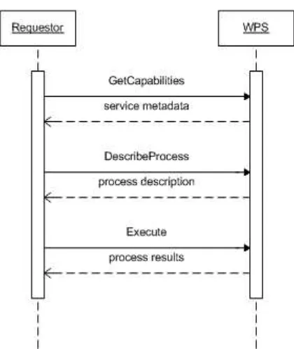
Figure 13. Basic WPS interaction
Therefore, the interface is held very generic and is mainly based on three operations as shown in figure 13. Since a WPS should be able to be integrated in to the OpenGIS framework, it has to offer the GetCapabilites operation generally described by the OWS Common specification. Besides the OWS Common metadata (see Section 2.3.4), and basic service metadata, all processes offered by the WPS are briefly described in the capabilities document. The GetCapabilities operation can only be invoked via HTTP-GET and the request should be Key-Value-Pair (KVP) encoded. A minimal request can be found in (OGC, 2007)
A requestor first requests the service metadata via the GetCapabilities operation. Detailed information is obtained by calling the DescribeProcess operation for an operation listed in the service metadata. Finally, the execute operation is invoked with all required input data identified by the DesribeProcess response. Especially, the flexibility of the WPS specification can be used for the workflow wrapping approach: All required workflow input data can be mapped to WPS input data.
Figure 14. Workflow Engine Wrapping Architecture
As depicted in figure 14, the client sees the Workflow engine as a simple WPS process and is not necessarily aware of the underlying Workflow engine. The OGC Discussion Paper 08-123 discusses a transactional extension for the WPS, which applies a generic approach and a concrete profile for BPEL. This profile allows clients to dynamically deploy and undeploy workflows as WPS processes. In the case of OWS-6, a static-non transactional approach is applied which wires a WPS process directly to a workflow in a BPEL engine.
This architecture has the advantage, that different Workflow engines can be exposed as a WPS processes without changing the workflow appearance to the client. The client always can invoke a WPS process independent of the underlying workflow engine or workflow script language. Besides, by encapsulating a workflow engine with a WPS, the advantages of a WPS can be used, such as integration into the OGC service stack, asynchronous execution and basic message structure interoperability combined with the flexibility of input data description.
5.1.3 Web Coverage Service
5.1.4 Web Feature Service
A Web Feature Service (WFS) allows standardized access to spatial vector data organized as features inside feature collections.
In principle, this approach faces similar limits to the WCS exposition described above. In detail, once a composition is deployed to the execution engine, invocation is
Wf-XML utilizes a loosely coupled, message-based approach to facilitate rapid implementation using existing technologies. It will describe the syntax of these messages in an open, standards-based fashion that allows for the definition of a structured, robust and customizable communications format.
Wf-XML can be used to implement three models of interoperability; specifically, chained workflows, nested workflows and parallel-synchronized workflows. Wf-XML supports these three types of interchanges both synchronously and asynchronously, and allows messages to be exchanged individually or in batch operations. Furthermore, this specification describes a language that is independent of any particular implementation mechanism, such as programming language, data transport mechanism, OS/hardware platform, etc.
However, Wf-XML has no SOAP binding defined and Wf-XML based services do not fit into the OGC service stack directly, because it e.g. does not support a GetCapabilities operation.
A RESTful Wf-XML (Wf-XML-R) developed in OWS-5 was used in this testbed, but but no specific implementation details were available to be included in this ER.
5.2 Data Transfer Patterns
Patterns for transferring and managing data have been studied extensively in the workflow research community. (see e.g. Russel et al., 2005) In terms of this testbed, only the transfer of data from the client to the workflow engine and from one workflow participant to another was relevant.
1. Keeping data in a centralized repository vs. keeping the data by the data generating entity
2. Sending data by value vs. send data by reference Both aspects are discussed in the following sections.
5.2.1 Data Management
In the OWS-6 testbed, all data (input data to the workflow and to the services) was kept at the corresponding entities. In other words, one participant has sent the data which serves as input for another participant either by value or reference (see next sub section) to the workflow engine, which dispatches the data (reference) to the relevant workflow partner. No centralized repository was used where workflow partners store and access the data.
5.2.2 Data Transfer
5.2.2.1 By Value
Sending data by value sends the whole data set from one participant to another. The workflow engines, as orchestrating entity, passes the data to the target participant. This concept has been proven useful only for small datasets and simple data structures, such as coordinate pairs, buffer distances etc, because the data has to pass the workflow engine and its pre determined communication channel. More efficient communication channels or timeframes could not be considered. Therefore, for larger datasets, sending data by
reference seems to be more useful.
5.2.2.2 By Reference
Sending data by reference does not send the actual dataset but only a pointer to the data. In the OWS-6 testbed, the data prevailed on the data generating services (e.g. WCS, WPS) and a URL was passed to fetch the data over the internet. The reference is passed via the workflow engine to the target participant. The actual data is then transferred via an external channel. This approach seems to be more applicable for large data sets, because, the data does not go through an intermediary and could be fetched via a chosen transport channel, which seems to be more efficient.
5.3 Workflow Response Delivery
a) the interface of the workflow (see section 5.1) b) the initial request based on a)
However, there are three different patterns for obtaining the result, which will be elaborated in the following sub sections.
5.3.1 Raw Data result
The data is delivered back as plain raw data. This pattern is related to Section 5.2.2.1 but is more strict in a sense that the data is delivered without any interface specific overhead. For instance, if a Geotiff image is requested, the image is delivered in binary format and not wrapped into other message structures.
For instance, WPS or WMS offer explicitly the option for delivering raw data but this concept can be used beyond these interfaces. In the OWS-6 testbed, this was especially useful for WPS delivering binary data, since the binary data had not to be encoded e.g. as base64 data. However, only one result can be delivered at a time.
5.3.2 Referenced Result
This pattern delivers only a reference to the data back in the meaning of section 5.2.2.2. In the OWS-6 testbed, this pattern was successfully combined with the previously described pattern: The raw data is referenced and only the reference is delivered back to the requestor. This has the advantage that multiple results could be returned back at once.
5.3.3 Encapsulated Result
Another option is to explicitly wrap the data in an interface specific encoding. For instance, gml features could be encapsulated in a wfs:FeatureCollection or in a ExecuteResponse document. This could be especially useful if the workflow is exposed via a known interface and only the specific interface response encoding is understood by the client.
In the OWS-6 testbed, the final workflow partner was a data providing service (WCS-T). The workflow engine stored all relevant results as new layers in that service and returned only a reference to the newly added layers. In other words, the results were encapsulated as WCS layers inside of the workflow and the requests and response message to fetch the data had to be according to this interface description.
5.4 Architectural Style Independent Workflows
The development environment is developed by SINTEF. It provides support for constructing (W3C and OGC) Web Services compositions and allows a user to annotate and discover Web Services including an extension for semantic information. The SINTEF Composition Studio has been chosen as the basis for the development environment because it is open source and operates on an abstract UML level when composing Web Services (Hoff et al., 2006).
Top-level processes
The main functionalities of the development environment are the creation of Web Service compositions, semantic annotation of Web Services and compositions, discovery of services, deployment of compositions and execution of compositions. Use of the development environment will typically only utilize parts of the available functionality. We will show two process models supported by the development environment.
Figure 15. Composing and execution of a service composition.
Figure 14 shows the process of creating and testing a service composition. This process will typically start with the creation of a new, empty service composition. To populate the empty composition with existing services a search for services will be performed. The result of the search can then be added to the composition. The service composition will then be edited, for instance to describe the control flow. After finishing the composition it must be translated to a language the execution engine understands. To test the finished service composition it can be deployed on the execution engine and executed within the development environment. This will allow a service composition developer to have access to both composing and testing facilities in the same environment.
Import of Web Feature and Processing Service
The Composition Studio has a local repository for resources transformed into UML representations, called Local Dictionary. With use of the import of service description menu it is possible to import a Web Feature Service. or WPS Figure 16 shows how to access the menu for importing WFS.
Figure 16. Import of Service Description.
After activating the import service description menu item a dialog window will appear, as seen in Figure 17. To import a WFS enter the base URL to the service. This will be used to parse the WFS description and create a UML representation in the Local Dictionary of the WFS. The local name is used for better naming of the UML resource.
The transformation from WFS to UML is quite simple. Given the URL to the WFS the WFS document is parsed and transformed into a UML package containing a UML class with a WFS stereotype. Then each of the features of a WFS is transformed into a UML property contained in the UML class. Table 1 shows how a Web Feature Service is represented in UML.
Table 1. An overview of the mapping between WFS and UML.
Deployment of a composition
Figure 18. The deployment dialogue window.
5.4.1 BPMN vs. UML 2.0 Activity Diagrams
The reason for using UML Activity Diagrams in favour of BPMN diagrams is that UML does also provide profiles that makes it easy to extend models with specific fields and annotations. For complex project, often UML Class diagrams UML Sequence diagrams are necessary, which could be easily integrated with UML Activity Diagrams.
Additionally BPMN 1.0 does not support data flow as well as UML activity diagrams. However, in BPMN 2.0, there are plans to increase the BPMN support for data/information models, and we will then look further into how to use BPMN as an alternative to UML activity diagrams in the future.
5.5 Asynchronous Workflow Participants
Message exchange in workflows can be either synchronous or asynchronous. Synchronous workflows have been studied in previous testbeds (see Section 4).
The workflow language and the workflow partners both have to support asynchronous message exchange. Since BPEL and WPS were the prominent representatives, this sections focus only on these technologies.
5.5.1 WPS-Push Model
Since the WPS was heavily used in the OWS-6 GPW exercise, the asynchronous capabilities of this service have to be analyzed. The WPS specification states in table 50 that the status attribute in the ResponseDocument element should be used to indicate an asynchronous pull request. The immediate status response would look for instance like:
Listing 8. WPS Pull Response Message
The statusLocation="http://geoserver.itc.nl:8080/wps/RetrieveResultServlet?id=1239702 719520" attribute (line 1) can be used to pull additional status requests. Until process completion, the status message will not change except the optional percentCompleted attribute.
Listing 9. WPS Pull Final response.
Listing 10. BPEL mechanism for WPS pull invocation.
Unfortunately, push support (see Section 4.3.1) is not yet specified in the current WPS specification.
There are generally two approaches to solve this problem:
5.5.1.1 Extending the WPS execute request
One option would be to directly extend the WPS request. The ResponseDocument would get two optional attributes in the <wps:ResponseDocument> element
callbackAddress
this attribute specifies the callback mechanism type. An urn shall be used which is indicated in the extended Capabilities metadata. To indicate the supported callback mechanisms, the service metadata should be extended with the following structure:
Listing 11. WPS Capabilities Extension
A <wps:CallbackOfferings> element has 0..n <wps:CallbackType> each containing a urn.
For instance, the urn:ogc:wps:async:push:url will be used to indicate that the process results shall be send to the url stated in the callbackAddress attribute.
Both attribute have always to be used in conjunction. The status attribute has to be therefore always turned to false.
5.5.1.2 Use optional message parts
WS-Addressing (OASIS, 2004) is a mainstream IT solution to this problem. The OASIS specification utilized the SOAP header to send a XML structure containing a callback address. This callback address should be used to push the data back, when the process has finished.
Listing 12. WS-Addressing Header Example
The WS-Addressing specification specifies its elements in detail. In the context of the WPS specification, if a WS-Addressing header is used, the expected response message to a request will be delivered to a the given address stated in the <wsa:Address> element. Therefore, this mechanism can be used in conjunction with the request methods outlined in the WPS specification.
In BPEL, the pattern described in listing 13 could be used to invoke a service with WS-Adressing.
Listing 13. WS-Addressing with BPEL
5.5.1.3 Comparison of both approaches
Both presented approach have certain advantages and disadvantages. Table 2 gives an overview:
Criteria WPS Inline Approach WS-Addressing
Use within mainstream IT-architectures
- +
SOAP + +
HTTP-POST + -