• Table of Contents
Fibre Channel for Mass Storage
By
Ralph H. Thornburgh
Publisher : Prentice Hall PTR Pub Date : April 01, 1999ISBN : 0-13-010222-9 Pages : 155
Slots : 1
With Fibre Channel, you can suddenly scale
your storage systems from gigabytes to
terabytes, and improve performance at the
same time -- all without disrupting systems,
networks, or applications.
Fibre Channel for
Mass Storage
walks you step-by-step
through the basics of Fibre Channel
technology, and demonstrates how to deploy
Hewlett Packard's advanced Fibre Channel
products to address your most critical
enterprise storage challenges. Coverage
includes:
enterprise storage technology of choice
Fibre Channel's architecture and six
functional levels
Fibre Channel Arbitrated Loop (FC-AL)
--an exceptionally effective storage system
topology
Peripheral devices, logical units, and
volume set addressing
Essential addressing techniques for
integrating Fibre Channel with HP-UX
Fibre Channel for Mass Storage
introduces
Hewlett-Packard's state-of-the-art Fibre
Channel product family, beginning with
Tachyon(r), the industry's first Fibre Channel
controller fully integrated on a single chip.
Learn about Hewlett-Packard's Fibre Channel
adapters for K-Class, T-Class, D-Class, and
V-Class Enterprise Servers and parallel clusters;
hubs, disk arrays, SCSI multiplexers, and
beyond.
• Table of Contents
Fibre Channel for Mass Storage
By
Ralph H. Thornburgh
Publisher : Prentice Hall PTR Pub Date : April 01, 1999ISBN : 0-13-010222-9 Pages : 155
Slots : 1
Copyright
List of Figures
Preface
What this book is about
Who should read this book?
Why is this book needed?
How to use this book
At a Glance
Acknowledgements
About the Author
Chapter 1. Overview of Fibre Channel for Mass Storage
Section 1.1. Current Mass Storage Architectures
Section 1.2. What is Fibre Channel?
Section 1.3. Fibre Channel for Mass Storage
Section 1.4. Advantages of Fibre Channel for Mass Storage
Section 1.5. Basic Terms
Section 1.6. Topologies
Chapter 2. Fibre Channel Functional Levels and Protocols
Section 2.1. Functional Levels
Section 2.2. FC-0: The Physical Layer
Section 2.5. FC-3: Common Services
Section 2.6. FC-4: Mapping
Section 2.7. Upper Level Protocols
Section 2.8. Classes of Service
Chapter 3. Fibre Channel Arbitrated Loop (FC-AL)
Section 3.1. FC-AL Characteristics
Section 3.2. Operations of the FC-AL
Section 3.3. Hubs
Section 3.4. Topologies
Chapter 4. Addressing
Section 4.1. The Addressing Limitations of HP-UX
Section 4.2. Addressing Methods for HP-UX
Chapter 5. Hewlett-Packard Fibre Channel Products
Section 5.1. CONTROLLER IC's
Section 5.2. Fibre Channel Adapter for the K-Class Systems
Section 5.3. Fibre Channel Adapter for the T-Class Systems
Section 5.4. Fibre Channel Adapter for the D-Class Systems
Section 5.5. Fibre Channel Adapter for the V-Class Systems
Section 5.6. Fibre Channel Arbitrated Loop Hub
Section 5.7. High Availability Fibre Channel Disk Array
Section 5.8. SCSI Multiplexer
Section 5.9. FC Switch
Section 5.10. Typical Hewlett-Packard FC Topologies
Chapter 6. Fibre Channel Futures
Section 6.1. Future Enhancements
Section 6.2. Sources for More Information Regarding Fibre Channel
Glossary
Copyright
Library of Congress Cataloging-in-Publication Data
Thornburgh, Ralph H.
Fibre channel for mass storage / Ralph H. Thornburgh. p. cm. -- (Hewlett-Packard professional books)
Includes bibliographical references and index.
1. Fibre Channel (Standard) 2. Computer storage devices. I. Title. II. Series.
TK7895.B87.T48 1999 004.6'6--dc21 99-24516 CIP
Credits
Editorial/production supervision: Nicholas Radhuber
Manufacturing manager: Alexis Heydt
Acquisitions editor: Jill Pisoni
Marketing manager: Lisa Konzelmann
Cover design: Talar Agasyon
Manager, Hewlett-Packard Retail Publishing: Patricia Pekary
Editor, Hewlett-Packard Retail Publishing: Susan Wright
Comments? Write to HP Retail Publishing at [email protected].
© 1999 by Hewlett-Packard Company Published by Prentice Hall PTR
Prentice-Hall, Inc.
Upper Saddle River, New Jersey 07458
Prentice Hall books are widely used by corporations and
government agencies for training, marketing, and resale. The publisher offers discounts on this book when ordered in bulk quantities. For more information, contact:
Phone: 800-382-3419, Fax: 201-236-7141 E-mail: [email protected]
or write:
Corporate Sales Department Prentice Hall PTR
1 Lake Street
Upper Saddle River, NJ 07458
All product names mentioned herein are the trademarks of their respective owners. All rights reserved. No part of this book may be reproduced, in any form or by any means, without
Prentice-Hall International (UK) Limited, London
Prentice-Hall of Australia Pty. Limited, Sydney
Prentice-Hall Canada Inc., Toronto
Prentice-Hall Hispanoamericana, S.A., Mexico
Prentice-Hall of India Private Limited, New Delhi
Prentice-Hall of Japan, Inc., Tokyo
Prentice-Hall (Singapore) Pte.Ltd., Singapore
List of Figures
Figure 1-1 Current Limitations 2
Figure 1-2 Basic Terms 7
Figure 1-3 Point-to-Point Topology 8
Figure 1-4 Two Point-to-Point Connections 8
Figure 1-5 Arbitrated Loop Topology 9
Figure 1-6 Fabric Topology 10
Figure 1-7 Typical Fibre Channel Campus Topology 11
Figure 2-1 Fibre Channel Protocol Functional Levels 14
Figure 2-2 Placement in a Topology 15
Figure 2-3 Functional Levels 16
Figure 2-4 Fibre Channel Framing levels 17
Figure 2-5 FC-0 Connectors 18
Figure 2-6 Fiber Cable Components 20
Figure 2-7 Light Transmission 21
Figure 2-9 8B/10B Encoding 24
Figure 2-10 8B/10B Translation 25
Figure 2-11 FC-2 Frame Structure 27
Figure 2-12 Frame Header Structure 28
Figure 2-13 FC-3 Common Services Level 31
Figure 3-1 FC-AL Private Loop 37
Figure 3-2 FC-AL Public Loop 38
Figure 3-3 FC-AL Fabric 39
Figure 3-4 Monitoring or Idle State 43
Figure 3-5 Arbitration Process 44
Figure 3-6 The Opened State 45
Figure 3-7 Open Loop 46
Figure 3-8 Closing the Loop 47
Figure 3-9 Cascaded Shortwave Hub Topology 50
Figure 3-10 Cascaded Long-wave Hub Topology 51
Figure 4-1 Target Address Space Limitations 54
Figure 4-3 Work-around for Target Address Limitations 56
Figure 4-4 Work-around for LUN Address Limitations 56
Figure 4-5 Addressing Methods 57
Figure 4-6 Hardware Path 58
Figure 4-7 Nibble Conversion of Loop Address on a 30-Slot Array 60
Figure 4-8 Example of LUN using Peripheral Device Addressing 61
Figure 4-9 Hewlett-Packard HA FC Disk Array 61
Figure 4-10 Example of an ioscan 62
Figure 4-11 Example of Logical Unit Addressing 63
Figure 4-12 Example for Converting the MUX Loop Address 64
Figure 4-13 Hardware Path for the MUX Control Port 65
Figure 4-14 Example Hardware Path for a Device on MUX bus 3 65
Figure 4-15 Example MUX ioscan with Attached Devices 66
Figure 4-16 Example of Volume Set Addressing 67
Volume Set Addressing 68
Figure 4-18 Deriving a LUN Hardware Path 69
Figure 4-19 Final Hardware Path for LUN 179 70
Figure 5-1 Hewlett-Packard's Fibre Channel Chips 75
Figure 5-2 TACHYON Internal Block Diagram 78
Figure 5-3 TACHYON Pin-out Block Diagram 80
Figure 5-4 A3404A Fibre Channel Adapter (for K-Class Systems) 82
Figure 5-5 A3636A Fibre Channel Adapter (for T-Class Systems) 83
Figure 5-6 A3591A Fibre Channel Adapter (for D-Class Systems) 84
Figure 5-7 A3740A Fibre Channel Adapter (for V-Class Systems) 85
Figure 5-8 A3724A/A4839A FC-AL Hub 86
Figure 5-9 Cascaded Long-wave Hub Topology 88
Figure 5-10 Cascaded Shortwave FC-AL Hub Configuration 90
Figure 5-12 Incorrect cabling example: more than one cable connection between hubs 91
Figure 5-13 Incorrect cabling example: more than two hubs connected 91
Figure 5-14 A3661A HA FC Disk Array 92
Figure 5-15 Basic Topology, High Availability Version: Host with Two FC I/O Adapters 94
Figure 5-16 Basic Topology, High Availability Version: Host with Four FC I/O Adapters 95
Figure 5-17 Basic Topology, NonHigh Availability Version: Host with Four FC I/O Adapters 96
Figure 5-18 Single-System Distance Topology 98
Figure 5-19 High Availability (redundant loop) Topology 101
Figure 5-20 High Availability, Distance, and Capacity Topology 104
Figure 5-21 Campus Topology 105
Figure 5-22 A3308A SCSI Multiplexer 106
Figure 5-23 FC-SCSI MUX Topology with Two DLT Libraries 107
Figure 5-25 Back view of the Hewlett-Packard Fibre Channel Switch 108
Figure 5-26 Example of FC Switch Configuration 110
Figure 5-27 Hewlett-Packard FC Mass Storage Topology 112
Preface
What this book is about
Who should read this book?
Why is this book needed?
How to use this book
What this book is about
This book discusses the implementation of Fibre Channel technology for Mass Storage environments. It opens with
discussions on storage architectures, their limitations, and how Fibre Channel helps to overcome these limitations.
Next, details of the Fibre Channel technology, focused on the mass storage application, are discussed. Addressing schemes for the Hewlett-Packard implementation are covered in detail as well as Hewlett-Packard products supporting this technology. And finally, future developments and improvements are
Who should read this book?
You should read this book if Fibre Channel is new to you or if you will be working with peripherals that are attached to a
Hewlett-Packard system using Fibre Channel technology. This is a brand new technology that is quickly becoming an industry standard. It is already being installed in data centers around the world and may very well be the next communications protocol installed at your location.
If you are a System Administrator and your job is to control configurations and resources of computer systems or do installation of peripherals, this book is a must. If you are a
Why is this book needed?
Fibre Channel is a new technology and many people are not familiar with its functionality or terminology. Therefore, this book was written to introduce new Fibre Channel users to this important, fast rising technology.
Publications that do exist on Fibre Channel, talk more
generically about the technology or focus on the networking aspects. This publication is focused on adding information on Fibre Channel as a technology applied to the mass storage environment and specifically how Hewlett-Packard is
How to use this book
This book can and should be used as a reference book. For example, if you are familiar with Fibre Channel you would want to review the functional levels in Chapter 2 and then read on from there. If you are familiar with Fibre Channel and only want to know how HP is implementing addressing, you could read
Chapter 4. However, if you are unfamiliar with Fibre Channel
you will want to start at the beginning, including this preface, and read through chapter by chapter. It is written in a
At a Glance
Following is a chapter-by-chapter glance at this book:
Chapter 1 This chapter discusses limitations of current mass
storage architectures, explains how Fibre Channel answers these limitations, and defines basic terms and topologies.
Chapter 2 This chapter details the functional levels of Fibre
Channel, emphasizing physical components. There are six levels, three are port levels and three are node levels.
Chapter 3 This chapter discusses the features and operations of
the Fibre Channel Arbitrated Loop (FC-AL), and explains how FC-AL is a very effective topology for mass storage. Hewlett-Packard has a commitment to this topology, as evidenced by its Fibre Channel hub product. This chapter will familiarize the
reader with the characteristics, operations, and advantages of FC-AL.
Chapter 4 This chapter explains why Fibre Channel is a fast,
flexible technology that enables a large number of devices to communicate. This chapter describes in detail Peripheral Device, Logical Unit, and Volume Set addressing, which is unique to Hewlett-Packard's HP-UX Operating System environment.
Chapter 5 This chapter presents an overview of the
Hewlett-Packard's Fibre Channel products, describes the systems that support Fibre Channel, and discusses how the products work together.
Chapter 6 This chapter discusses the future developments and
improvements to Fibre Channel and how to get more
Acknowledgements
I would like to acknowledge the following people for their efforts and work they have accomplished for the Fibre Channel
initiative within Hewlett-Packard.
Kyle Black for his technical reviews of this material during development.
Paul McGowan for his support while writing this book and for his technical reviews of the material.
Maris Montanet for her work writing product service manuals and an HP Journal article introducing Fibre Channel.
Judy Smith for her work writing training manuals for the HP Fibre Channel field training and an HP Journal article introducing the Hewlett-Packard Fibre Channel chip.
Debbie Clingingsmith for her work writing and delivering the HP Fibre Channel field training material.
Russ Routh for his work on the HP Fibre Channel Arbitrated Loop Hub.
Barry Schoenborn for all his efforts and support during the development of the HP Fibre Channel field training material and this book.
Bobbi Gibson the Information Engineering department manager for supporting me in my efforts to write this book.
About the Author
Ralph Thornburgh has worked for Hewlett-Packard Company for 24 years as an IT trainer, IT Data Center Manager, and Learning Products Engineer (technical writer).
During that time he has created twenty-one training classes for Hewlett-Packard data center employees and support personnel worldwide. He has also written fifteen user manuals and
numerous technical support manuals.
He lead the team that wrote the multicourse training program for Hewlett-Packard's implementation of Fibre Channel for Mass Storage and two other classes for Hewlett-Packard Fibre
Channel peripheral devices.
While at Hewlett-Packard, Ralph held a secondary teaching certificate for three years. He designed and delivered computer class curriculum, to include operating systems and computer operations, for The Computer Learning Center in Santa Clara, California.
Ralph has also designed, developed, and delivered an American Sign Language (ASL) course for middle-school children.
Ralph was also in the U.S. Army for eleven years, part of which was spent in the California Army National Guard. There he was the section training sergeant, training soldiers in technical skills such as Aviation Electrician, as well as in Basic Combat Skills, such as land navigation (map reading) and basic
Chapter 1. Overview of Fibre Channel for
Mass Storage
This chapter discusses:
Limitations of current mass storage architectures
How Fibre Channel answers these limitations
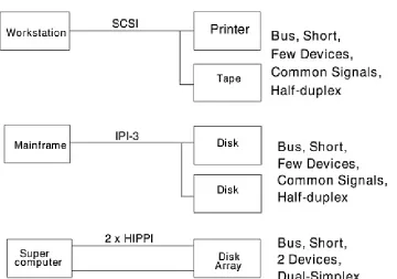
1.1 Current Mass Storage Architectures
Current architectures (data transfer protocols) have three major problems:
1. Limited speed
Limited distance between devices Limited number of devices supported
Figure 1-1. Current Limitations
For example, the small Computer System Interface (SCSI) parallel interface is restricted to:
32 SCSI devices per bus a double cable system
In today's modern computer system environments, these restrictions are very limiting to design and confining in space, and it gets worse. The two-byte wide SCSI P-cable limits
configurations to 16 devices.
The single-ended SCSI protocol is limited to eight IDs or
addresses per bus (seven devices and one controller), and wide differential SCSI is limited to 16 IDs per bus (15 devices and one controller) to configure a one-terabyte disk storage unit. A fully redundant disk array would require 30 SCSI IDs (two per bus).
1.2 What is Fibre Channel?
Fibre Channel is a new communications protocol designed to overcome the limitations of existing architectures. It is a generic data transport mechanism with the primary task of transporting data at the fastest rate possible using current technology. Fibre Channel is a scalable interface for achieving high-speed data transfer rates among heterogeneous systems and peripherals. System types could include supercomputers, mainframes, workstations, and desktops, (personal computers). Peripherals could include mass storage devices such as disk arrays and possibly tape libraries. The main purpose of Fibre Channel is to have any number of existing protocols over a variety of physical media and existing cable options. The following table demonstrates the various speeds that can be attained using the different cable types.
Type/Speed
(Mhz) Single Mode@9 um Multi-mode@50 um [email protected] um Co-ax Mini-Co-ax Twinax STP
133 100
m 42 m 93 m 80m
266 1300nm @10
km 780nm @2 km 780nm @1 km 100m 28 m 66 m 57m
533 1300nm @10
km 780nm @1 km 780nm @1 km 71m 19 m 46 m 46m
1063 1300nm @10
km 780nm @500m 780nm @175 m 50m 14 m 33 m 28m
2125 1300nm @2
km 780nm @500m
km m
1.2.1 Fibre Channel for Networking
Fibre Channel can be used for networking. The Fibre Channel standard was written to also cover networking protocols
(system-to-system communication). Hewlett-Packard's
networking implementation uses a speed of 25 Megabytes per second, (M/bytes/s, also known as Mbps) or 266 (265.625) megabaud. This is also known as quarter speed, with full speed being 100 Mbytes/s or 1063 (1062.5) megabaud. Full speed is also known as gigabit speed. Consult the publications listed in
Section 6.2 for more information on Fibre Channel as applied to
1.3 Fibre Channel for Mass Storage
Since Fibre Channel is a generic data transport mechanism,
Fibre Channel can transmit a number of existing networking and I/O protocols:
I/O protocols: SCSI
HIPPI IPI
Network protocols: IP
IEEE 802.2
Hewlett-Packard has chosen to support the SCSI-3 protocol over Fibre Channel for its mass storage environment. Mass storage consists of several device classes:
tapes disks
1.4 Advantages of Fibre Channel for Mass
Storage
There are some definite advantages to using Fibre Channel over other architectures. Although this is not an all-inclusive list, these are the major advantages:
1.4.1 Distance
Hewlett-Packard supports up to 10,000 meters (10km) between the computer (or system) and the peripheral. What this means is that between the computer and the peripheral there can be a distance of 10 kilometers. The next section, " Topologies," will describe this in more detail, however, the distance advantage is an excellent solution for the campus-type environment.
1.4.2 Speed
Fibre Channel permits a theoretical speed of up to 4000 Mbps. (As mentioned previously Hewlett Packard supports 1063
Mbps.) Speeds depend greatly on the design of the pieces and parts that are connected within the topology between the
computer and the peripheral. Our challenge within the industry now is to determine how to achieve these higher speeds
allowed by the Fibre Channel standard. This speaks directly to performance because with the speeds capable with Fibre
Channel throughput increases by four or five times over current channels.
Computer system environments today are very limited in the number of devices that can be connected together. They are also limited in that today's configurations do not easily allow the introduction of new technologies, protocols, or even different protocols simultaneously.
Fibre Channel addresses these issues by allowing:
1.5 Basic Terms
A set of new terms having no previous association with other protocols has been defined for Fibre Channel. For example, SCSI has Initiators and Targets, and Fibre Channel has
Originators and Responders. In Fibre Channel, the Originators are devices that originate (initiate) a transaction or operation. The Responders then, answer the operation of the Originators. Also refer to the glossary in the back of this book for complete definitions of all terms.
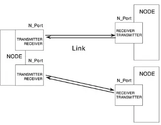
The following pages will describe more words, as well as the names of some of the pieces and parts of Fibre Channel technology/topologies. A node is a device. A device is any processor or mass storage subsystem with Fibre Channel functionality. A node has at least one port (N_Port, the 'N' stands for node) and can have multiple ports. A port is the connecting interface between the cable and the device, located on the device. The cable is referred to as the link. Fibre Channel is based on full duplex operation, therefore two fibers, (TX and RX) one to transmit and one to receive, are required to operate a port. The term fiber in this case can be a copper cable or an optical strand cable.
1.6 Topologies
1.6.1 Point-to-Point
The first topology to discuss is the simplest, it is called a point-to-point topology. It is two nodes (devices) connected together. One node could be a computer system and the other node could be a disk array.
Figure 1-3. Point-to-Point Topology
This particular topology uses two nodes (each node must have at least one port), and the nodes are connected using one link or cable. The point-to-point connection guarantees instant
access with no interference from any other node or application. If a peripheral node, such as a disk array, has two N_Ports, access to the disk array could be shared between two computer systems. For example, the disk array could act as a repository of common software for two computer systems. This would be considered two point-to-point connections. See Figure 1-4.
A point-to-point connection may also be considered a two-node loop. Hewlett-Packard's implementation of point-to-point is a two-node loop. This brings us to our next topology to be discussed.
1.6.2 Arbitrated Loop
A loop, called Fibre Channel Arbitrated Loop (FC-AL) can have up to 127 ports connected in series (one right after the other) continuing around and back to the originator. For example, the node 1 transmitter is connected to the node 2 receiver, the node 2 transmitter is connected to the node 3 receiver and so on until the final node transmitter is connected to the node 1 receiver, thus completing the loop. Figure 1-5 illustrates this example.
A node loop port (NL_Port) wins arbitration on the loop and establishes a connection with another NL_Port on the loop. At the time the connection is established it is considered to be a point-to-point connection or two-node loop.
In an arbitrated loop only the two connected ports can communicate at any given time. All the other ports act as
repeaters. When the communication comes to an end between the two connected ports, the loop becomes available for
arbitration and a new connection may be established. Fairness is provided for during arbitration to provide equal access to all ports. The FC-AL features, operations, and Hewlett-Packard's implementation will be discussed in further detail in Chapter 3.
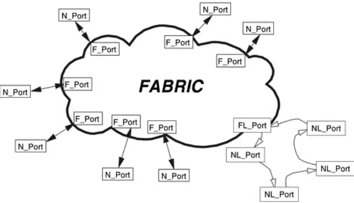
1.6.3 Switch Topology or Fabric
Unlike the FC-AL topology, many connections may be
established within the fabric. It can be compared to a telephone system where many phone calls may be occurring all at the same time.
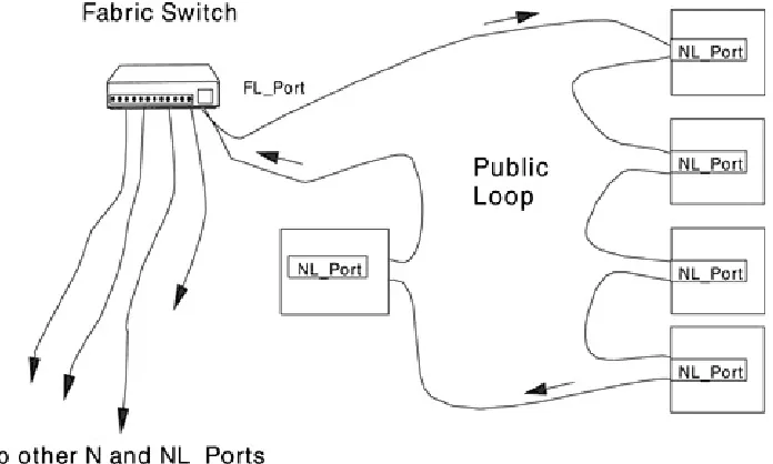
Any node can be attached to a fabric through the N or NL_ports by way of a link. The port in the fabric is called an F_Port. An N_Port attaches to an F_Port. If an NL_Port is attached to a fabric, then the fabric port is an FL_Port.
Figure 1-6. Fabric Topology
1.6.4 A Typical Campus Topology
A campus topology is nothing more than cabling buildings
together so data can be transferred from a computer system in one building to storage devices, whether they be disk storage or tape storage for backup or some other devices, in another
building.
Chapter 2. Fibre Channel Functional
Levels and Protocols
This chapter discusses:
Functional levels of Fibre Channel
- FC-0 Level Physical
- FC-1 Level Encode/Decode
- FC-2 Level Framing protocol/Flow control
- FC-3 Level Common services
- FC-4 Level Protocol mapping Upper Level Protocols
Physical components
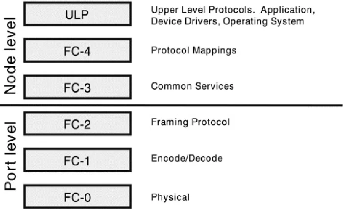
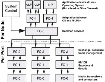
2.1 Functional Levels
Fibre Channel Protocol (FCP) functional levels are FC-0 through FC-4. The FC-3 and FC-4 levels are outside the port level,
permitting the sharing of resources of several ports in the event of future extensions. Applications lie above the FC-4 level. For example, the peripheral drivers for a SCSI application that typically communicates with Host Bus Adapters (HBAs) will communicate with the FC-4 level.
2.1.1 Placement in a Topology
As shown in Figure 2-1, FC-0, FC- , and FC-2 are implemented at the port level. FC-3, FC-4, and the Upper Level Protocols (ULPs) are implemented at the node level. Fibre Channel
considers that which is not visible on the link (above the FC-0 physical level) to be system dependent, and simply identifies the functions to be performed. It does not require allocation or placement.
Figure 2-2 shows an example of a simple point-to-point (two-node loop) topology to identify where the functionality of each level resides. FC-0, FC-1, and FC-2 are all implemented at the Port level. This means that each Port has the functionality of these levels. FC-3, FC-4, and ULPs are all implemented at the Node level.
Figure 2-2. Placement in a Topology
Figure 2-3 shows another way to demonstrate this. The
of FC-0, FC-1, and FC-2, there is only one FC-3, the common services level. That is because the FC-3 functionality may interact with multiple ports on a node. And then again above the FC-3 level, there are multiple FC-4s and ULPs. That is because there may be multiple ULPs within a node which map through multiple FC-4s.
Figure 2-3. Functional Levels
Figure 2-4 shows yet another example. This Figure clearly
shows that there are five levels used by Fibre Channel, (FC-0 through FC-4) separating the Upper Level Protocols into the system interface. Also, you can see that FC-4 can accommodate not only the channel protocols of SCSI, IPI and others, but can also accommodate network protocols like IEEE 802.2.
2.2 FC-0: The Physical Layer
Level FC-0 deals with the physical variants: fiber
connectors receivers
data encoders/decoders serializers/deserializers transmitters
FC-0 deals strictly with the serial bit stream to be sent and
received, and the conductors used to transmit that stream. This layer is called the physical layer. The Fibre Channel standard calls this function the Link Control Facility (LCF). The
requirements are different for different types of media and different data rates.
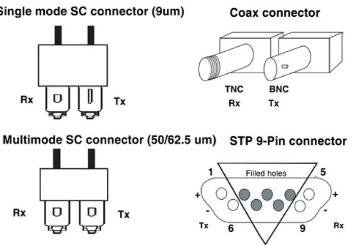
2.2.1 Connectors
optic cable. Single mode fiber optic cable is thinner and has less bandwidth than multimode cable. Therefore, single mode cable is used for long distance transmissions, 10,000 meters (10km), where as multimode cable is used for shorter distances, 500 meters.
In that case then, an example for use might be to connect two buildings some distance away from each other with single mode fiber optic cable. Then, within each building, connect each floor using multimode cable.
A word of caution, when working in a mixed environment of single and multimode cabling, be aware that the connectors have been keyed to prevent accidental connection of single mode to multimode or the reverse. However, the keying of the connectors is not perfect nor completely standardized. Also, multimode fiber cable does not work with single mode
transmitters and receivers. The single mode light "rattles
around" in the big 50 or 62.5 um fibers and dissipates quickly, causing data loss.
Currently, Hewlett-Packard only supports fiber optic cable with its use of Fibre Channel and therefore only uses the SC
connectors shown in Figure 2-5.
The Fibre Channel standard does provide for connections to co-ax and copper cabling.
For co-ax cable:
the TNC for receive the BNC for transmit
For copper cable the shielded twisted-pair (STP), 9-pin D-type connector (DB9), is used. To prevent accidental attachments, the middle five holes in the Fibre Channel DB9 female connector are filled.
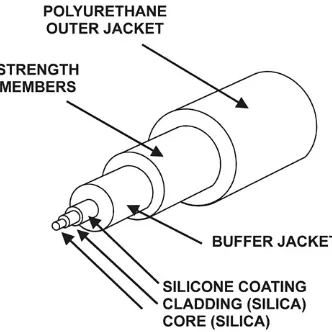
2.2.2 Fiber Optic Cables
Figure 2-6 shows a typical fiber cable and its major
let it escape.
Figure 2-6. Fiber Cable Components
Then the cladding is wrapped by a coating which is in turn
wrapped by the buffer jacket. This is all done so the light stays within the core. However, the core fiber itself is very thin and fragile. Therefore to give strength to the cable and more
protection to the core fiber, the buffer jacket is wrapped with a strengthening material. Finally, all of these layers of fiber and material are wrapped with the polyurethane outer jacket. Fiber cable is not subject to electromagnetic interference, and since the data is transmitted by light it is secure from eavesdropping.
Figure 2-7 demonstrates how light travels through the core. It
keeping the light in the core.
Figure 2-7. Light Transmission
Figure 2-8 shows what happens when the bend radius of fiber
cable is exceeded. The maximum bend radius is 3 cm. If the cabling is bent beyond 3 cm, data loss or data corruption is likely to occur. The core fiber may also crack or break.
2.2.2.1 OFC and non-OFC
Open Fibre Control (OFC) is a safety feature used to prohibit the laser light from functioning when there is a break or disconnect in the fiber cable. This is used specifically with high intensity laser lights. Hewlett-Packard uses non-OFC because the lasers are of low intensity. Therefore, the laser light is not turned off when there is a disconnect. However, this does not mean you should look at or point the fiber cable directly at your eye, since there still could be some damage. When checking a fiber cable to see if a laser light exists, point the cable end at a white piece of paper. If a red dot appears on the paper, then the
transmitting laser is functioning.
2.2.2.2 Wavelength
Wavelength is a topic related to single and multimode
connectors. Long wave lasers are used for long Fibre Channel links, from approximately 500 to 10,000 meters. They are typically used with single mode fiber of a 9-micron core size. Short wave lasers are used for FC-AL links up to approximately 500 meters. They are typically used with multimode fiber. The preferred fiber core size is 50-micron. 62.5-micron core size is also supported for compatibility with existing FDDI installations. However, fiber of this type has smaller bandwidth and, in this case, the distance is limited by the fiber bandwidth. The length recommendation for the 62.5-micron fiber cable is 175 meters. When pulling new cable, it is recommended that the customer pull both 9- and 50-micron cable to accommodate future
2.3 FC-1: The Transmission Protocol Level
The FC-1 level defines the transmission protocol including the 8B/10B encode/decode scheme, byte synchronization, and character-level error control. This protocol uses the 8B/10B encoding scheme that encodes 8-bit bytes into 10-bit
transmission characters. The 8B/10B encoding was developed by IBM and was determined to be the best for the expected error rate of the system.
The 8B/10B code has outstanding line characteristics including long transmission distances and very good error-detection capability. The 8B/10B code finds errors that a parity check cannot detect. Parity does not find even numbers of bit errors, only odd numbers. But 8B/10B finds almost all errors. Fibre Channel also employs a Cyclic Redundancy Check (CRC) on transmitted data. This also assists with error detection.
To assist with transmission the 8B/10B code uses 12 special characters. However, we are only concerned with one, the 28.5 special character. At present, it is the only special character used by Fibre Channel in the 8B/10B code.
2.3.1 8B/10B Encoding
The format of the 8B/10B character is Ann.m, where:
A is equal to "D" for data or "K" for a special character
nn is the decimal value of the lower five bits of a byte (bits EDCBA)
m is the decimal value of the upper three bits of a byte (bits HGF)
Figure 2-9 shows the translation of the HEX number 45.
Figure 2-9. 8B/10B Encoding
The 8B/10B encoded bytes have a property know as "disparity," which can be positive, negative, or neutral. An 8B/10B byte has negative disparity if there are more binary ones in the byte than binary zeroes. Conversely, the byte has positive disparity if
2.3.2 K28.5 Special Character Encoding
The K28.5 special character has the following components: K stands for special character
28 is the decimal value of bits EDCBA -- 11100 "." is a period
5 is the decimal value of bits HGF -- 101
Figure 2-10 shows the translation of the HEX number BC.
2.3.3 FC-1 Transmission Word
A transmission word is composed of four transmission
characters. Remember, the 8B/10B code encoded an 8-bit byte into a 10-bit character. Therefore, a transmission word is a 40-bit group of four 10B transmission characters. A transmission word can be one of two kinds:
data the first transmission character is an encoded data byte
ordered set the forth transmission character is the K28.5 special character
If the transmission word is data, each of the four transmission characters is an encoded data byte.
If the transmission word is an ordered set, the first byte is a K28.5 transmission character. The other three transmission characters are normal encoded data bytes. Ordered sets permit control functions to be imbedded in the bit stream. One simple use of ordered sets is to determine at a receiver where word boundaries are. If all transmission words are data transmission words, the receiver has only a 2.5% chance of getting it right (that is, one in 40 bits).
2.3.4 FC-1: Ordered Set
Frame delimiter This defines what class of service is
required. (Classes of service will be explained later in this chapter.) The frame contains a start of frame (SOF) and an end of frame (EOF) delimiter.
Primitive signals There are two kinds of primitive signals: - The ordered set may be a primitive signal used for buffer-to-buffer flow control.
- There is an ordered set for idle primitives. Idles are words that fill the space between frames. In Fibre Channel, the transmitter must continuously send something over the media. This helps preserve bit, byte, and word synchronization, and permits faster communication.
2.4 FC-2: Framing Protocol
The FC-2 framing protocol manages flow control so data will be delivered with no collisions or loss. This level defines the
signaling protocol, including the frame and byte structure, which is the data transport mechanism used by Fibre Channel. The framing protocol is used to break sequences into individual frames for transmission, flow control, 32-bit CRC generation, and various classes of service.
To aid in data transfer, FC-2 provides for the following elements: Frames basic units of information transfer. The maximum payload of a frame is 2112 bytes.
Sequences are made up of one or more frames. FC-2 names each sequence and tracks it to completion.
Exchanges are the largest construct understood by FC-2. An exchange is a unidirectional or bidirectional set of
nonconcurrent sequences. SCSI-3 FCP uses bidirectional exchanges, with information passing in one direction at a time. To send data in the opposite direction, sequence
initiative is passed from one port to another and back again. Each port generates one or more sequences within the
exchange.
Packets are made up of one or more exchanges.
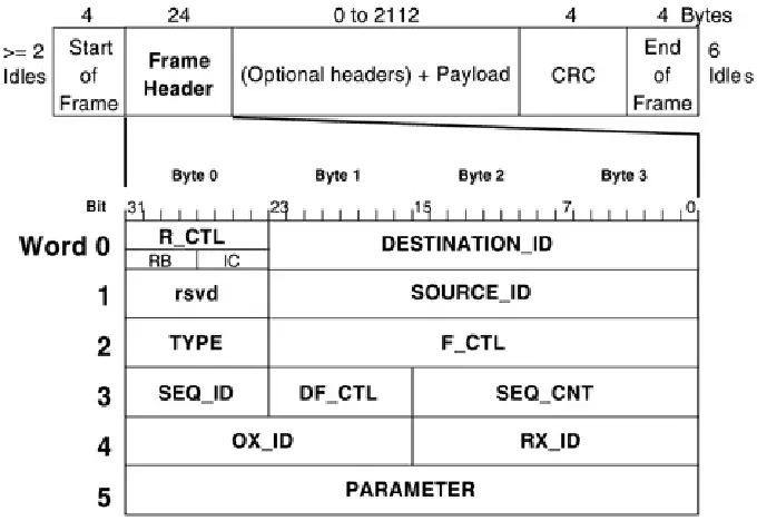
2.4.1 Frame Structure
Figure 2-11. FC-2 Frame Structure
The total length of the frame is 2148 transmission characters or 537 transmission words. The SOF, CRC, and EOF are all one transmission word in length with the frame header being six transmission words in length. The frame is followed by a minimum of 6 idles (or 24 transmission characters).
2.4.2 Frame Header Structure
The frame header is divided into fields to carry control information. The following figure shows these fields.
Table 2-1. Frame Header Structure Explanations
Routing Control (R_CTL)
Contains IC (Information Category) and RB (Routing Bits) subfields. Routing Bits indicate the frame type. The IC field indicates payload content (for example, SCSI status).
Destination
ID (D_ID) The native address of the destination N_Port, a well-known address, or analias address.
Source ID
(S_ID) The address identifier of the source N_Port.
Type The protocol associated with the payload (for example, SCSI-3)
Frame Control
(F_CTL) Bits that identify the transfer of sequence; beginning, middle, or end ofsequence; and end of connection.
Data Field Control (DF_CTL)
Sequence ID
(SEQ_ID) A unique numeric sequence identifier between two ports.
Sequence Count (SEQ_CNT)
A 16-bit rollover frame counter or frame identifier.
Originator Exchange ID (OX_ID)
A number an exchange originator uses to uniquely identify an exchange.
Responder Exchange ID (RX_ID)
A number like OX_ID, but for the exchange responder.
2.5 FC-3: Common Services
The FC-3 level, located at the center of the functional levels, concerns itself with functions spanning multiple N_Ports. The FC-3 level is the single point in the architecture through which all traffic must flow in both directions. The FC-3 level will
contain services that are common (available) to all ports on a node.
A node may have several ports. A node may also have several ULPs and FC-4 level mappings. However, there is only one FC-3 Common Services level per node. The FC-3 level can manage a set of tables holding the login information for other active ports. Each port on the FC-3 level knows which ports are busy and which exchanges they are busy with.
Figure 2-12 shows where the FC-3 level fits into the overall
scheme of all the Fibre Channel levels.
Currently there are three functions defined within the FC-3 level standard:
Striping Used to achieve higher bandwidth. Striping allows multiple links simultaneously and transmits a single
information unit across multiple links employing multiple N_Ports in parallel.
Hunt Groups Are a group of N_Ports associated with a single node. they permit any N_Port on the node to receive
information containing the correct alias identifier.
Multicast This can be compared to a broadcast message. It allows a single information unit to be transmitted to
multiple N_Ports on a node.
The FC-3 level knows nothing about the topology of Fibre Channel or the physical signaling at the lower levels. This is handled by FC-1 and FC-2 levels. FC-3 understands if there are multiple ports attached to a node and if they may participate in multiport operations like multicasting. Knowing which ports are busy allows the FC-3 level to route exchanges between two N*_Ports and FC-4s.
2.6 FC-4: Mapping
Mapping is a set of rules that is defined to move information from the Upper Level Protocol interfaces to the lower Fibre
Channel levels. the ANSI SCSI committee and the Fibre Channel committees are currently defining these rules.
Currently the rules provide for transforming information units into Fibre Channel sequences and exchanges and back again. When fully developed, these mapping rules are intended to provide clear mapping instructions between the Upper Level Protocol (ULP) and the FC-3 and FC-2 levels to enhance interoperability between applications.
To send data, the FC-4 level takes a unit of information (this is the payload in a frame and is the actual data that is being
2.7 Upper Level Protocols
The ULPs allow two devices to communicate. For example, a computer sends data to a disk to be stored for later use, or the communication that takes place in a client/server relationship. There are many standards currently defined that have been in use for years that enable interoperation, such as SCSI or IPI. A goal of Fibre Channel is to provide a structure where legacy ULPs would continue to operate, preserving the software
2.8 Classes of Service
Fibre Channel classes of service are managed by the FC-2 level. Currently there are three classes of service defined by the
standard:
Class 1 Dedicated connection service. - Connection-oriented
- Acknowledged delivery Class 2 Multiplexed service.
- Connectionless
- Acknowledged delivery
Class 3 Datagram service. This is the current class of
service provided for by Hewlett-Packard. The device drivers determine if data is not received and needs to be
retransmitted.
- Connectionless
- Unacknowledged delivery
Chapter 3. Fibre Channel Arbitrated Loop
(FC-AL)
This chapter discusses:
FC-AL Characteristics
- Types of Loops Operations of the FC-AL
- Primitive Signals and Sequences
- Arbitrated Loop Physical Address
- Loop States and Operation Hubs
3.1 FC-AL Characteristics
There are three topologies supported by Fibre Channel: loop, point-to-point, and switched. FC-AL is the loop topology that will be discussed here. The FC-AL is a means by which to connect two or more (up to 126) devices in a serial loop configuration. This solution is considered low cost because it does not use hubs and switches in small to medium
configurations. It also provides capability to connect to larger loops and fabrics where hubs and switches are used.
In the FC-AL each port discovers when it has been attached to a loop. Addresses are assigned automatically on initialization. Access to the loop is arbitrated, there are no collisions and there is no single permanent loop master.
FC-AL permits fair access on a single arbitrated loop. Access fairness means every port wanting to initiate traffic will have the opportunity to own the loop and initiate traffic before any other port has the opportunity to own the loop for the second time.
3.1.1 Types of Loops
3.1.1.1 FC-AL Private Loop
A private loop is enclosed and known only to itself. Figure 3-1
demonstrates a common configuration used with FC-AL for Fibre Channel Mass Storage. In this example, the processor node
only has one Fibre Channel host bus adapter (HBA).
The processor node is connected to the hub. Then the three devices, in this case disk arrays, are connected to the hub and the loop is formed. If the hub is not used then the connection with all three disk arrays cannot be made. A connection to only one, in point-to-point fashion, could be accomplished. Another option would be to install three HBAs into the processor node and connect each to a disk array separately.
The hub then, provides an advantage in saving HBA slots in the processor node and allows multiple storage devices to be added to the loop. Currently, this is the type of loop configuration
Hewlett-Packard supports.
3.1.1.2 FC-AL Public Loop
Figure 3-2. FC-AL Public Loop
Figure 3-3. FC-AL Fabric
3.2 Operations of the FC-AL
3.2.1 Primitive Signals
Table 3-1. Primitive Signals
Signal Description
ARB(x) Arbitrate address x for loop control
OPN(y) Open one other NL_Port
- Full duplex
- Half duplex
OPN(r) Replicate
- Broadcast
- Selective replicate or multicast
CLS Close the circuit at the NL_Port
MRK(tx) Synchronization signal 't' from 'x'
Note:
The 'x' is the address of the port wanting to own the loop and the 'y' is the address of the port to be opened.
Primitive signals are sent by a transmitting port and recognized and acted upon by a receiving port. Currently, the MRK signal is not supported by Hewlett-Packard.
Primitive sequences are not recognized or acted upon until the third consecutive occurrence of the ordered set. Currently, there are only three primitive sequences used:
LIP Loop Initialization LPB Loop Port Bypass LPE Loop Port Enable
The LIP sequence allows for discovery of ports on the loop. This means that when a new node is connected to a loop, the LIP sequence discovers it and allows for the new node to be initialized on the loop.
3.2.3 Arbitrated Loop Physical Address (AL-PA)
All ports have a 24-bit native address identifier, called the N_Port ID. The AL-PA is in the lower eight (8) bits of this
identifier. The lower the 8-bit address, the higher the priority is for arbitrating. An 8-bit field can have values from 0255, or 256 values. However, not all of these are used for physical
addresses.
AL-PA values must have neutral disparity. (Remember that 8B/10B encoding has positive, negative, or neutral disparity.) There are only 134 neutral disparity values out of the set of 256 8-bit addresses. 126 values, of the 134, are used for port
addresses and 8 are used for control functions. Hewlett-Packard uses addresses 00-EF. See Table 3-2 for further reference.
Table 3-2. AL-PA Values
Value Description
00 Reserved for FL_Port (high priority)
01-EF Available for active NL_Ports (126 valid neutral disparity values)
F0 Reserved for access fairness algorithm (lowest priority)
F1 - F6 Invalid
F7 Used with initialization primitive sequences
F8 Used with initialization primitive sequences
F9-FE Reserved (3 valid)
FF Replicate request (low priority) or to address "ALL"
3.2.4 Loop States and Operation
3.2.4.1 Operation Over view
There is a controlled arbitration process for a port to gain control of an arbitrated loop. The Open NL_Port selects a
destination NL_Port on the loop before a frame is transmitted. The arbitrating port releases control of the loop when frame transmission is complete.
the open ports can now send command or data frames.
After completing the information exchange, the port that won arbitration sends a CLS primitive to the destination port. Both ports now return to the monitoring state.
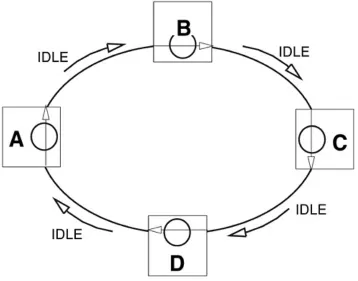
3.2.4.2 The Monitoring State
After port initialization, all ports start in the monitoring state, the loop is idle, no data is being transmitted, and there is no activity. The loop at this time is considered to be closed. While in the monitoring state, ports act as repeaters and are looking for primitive signals and sequences to act upon. Before any port arbitrates for the loop, the loop is filled with Idles.
3.2.4.3 The Arbitration Process
To begin the arbitration process, a port, in this example Port A, sends the primitive signal ARB(a) to notify the loop of its
intention to own the loop. Port A wins arbitration when the ARB(a) is returned to it. Receiving its ARB(a) means no higher priority NL_Port needs the loop at this time.
When Port A wants to acquire the loop, there can be different conditions on the loop. For example:
Some other port may already have control of the loop.
Several ports may be trying to acquire the loop at the same time.
Port A will win when:
No other port controls the loop, and
No port with a lower AL-PA address (higher priority) is arbitrating.
Once a port has acquired the loop, it opens the loop, preventing all other ports from acquiring the loop. It receives and discards all ARB(x) primitive signals.
3.2.4.4 The Open State
In this example, Port A has acquired the loop. It is now in the Open state with the loop physically open at Port A. Nothing may be done until Port A has completed a circuit with its intended destination, in this example, Port C.
Port A sends the OPN primitive signal naming C with an
OPN(c,a) for full duplex or an OPN(c,c) for half duplex. Port C is monitoring the loop, acting as a repeater, and listening for any ordered set pertaining to it. Once it receives the OPN primitive signal from Port A, it enters the Open state and physically opens the loop at its port.
The loop is now open between Port A and C and is considered to be a point-to-point connection.
3.2.4.5 Open Loop
Both Port A and Port C have opened the loop. Upper level
protocol frames and link control frames may now be sent back and forth.
The circuit formed is essentially a point-to-point link between A and C. This is a dedicated path for the duration of the
transaction.
Ports B and D are acting as repeaters but are listening for specific ordered sets as before.
3.2.4.6 Closing the Loop
Either one of the Open ports may initiate the closing procedure by sending a CLS primitive signal to the other. In this example, Port A initiates the closing by sending the CLS signal.
Once a port has sent a CLS primitive signal, it may not send frames or R_RDYs. However, it may still receive frames and R_RDYs.
The port receiving the first CLS primitive signal, here, Port C, does not have to close its circuit right away. It may continue to send frames. Once its operation is complete, it sends a CLS primitive signal back to the other port, Port A.
Figure 3-8. Closing the Loop
Once the loop is closed it returns to the state or condition shown in Figure 3-4. There is no activity and all nodes are
retransmitting idle signals. When the loop is closed, other ports may acquire the loop.
3.3 Hubs
Hewlett-Packard's implementation of FC-AL for a private loop includes a hub. FC-AL hubs connect devices to the loop. It is a simple way to connect participants in a private loop. There are two types of hubs:
Passive, which only reacts to ports being inserted into or removed from a loop
Active, which are able to do configuration changes dynamically, based on some controlling protocol.
Some hubs can sense or manage configuration changes in the loop, including:
- knowing when NL_Ports are added - knowing when NL_Ports are removed
- knowing when address changes occur for an entire set of NL_Ports
- switching NL_Ports into or our of a loop
Hubs also provide port bypass circuits to "heal" a loop when a device is removed or fails This allows for less disruption in
operations. Hubs help solve the problems of cabling devices and keeping track of which loop a device is on. With central cabling by way of the FC-AL hub, it is easy to add and remove devices from arbitrated loops.
Extremely fast solution for connecting peripherals and hosts (nodes)
Up to 124 NL_Ports per loop
Loop topology eliminates wiring clutter FC-AL hubs enhance subsystem availability
3.4 Topologies
There will be more information about hubs and specifically Hewlett-Packard hubs in Chapter 5. However, for now, to
demonstrate a couple of topologies using hubs see Figures 3-9
and 3-10.
Figure 3-9. Cascaded Shortwave Hub Topology
3.4.1 Cascading Shortwave Hubs
A server with an FC-AL, short-wave host bus adapter (HBA) can connect to an FC-AL hub 500 meters away. Each of the 10 ports on the hub can connect to an FC-AL device up to 500 meters away.
Cascaded hubs use one port on each hub for the hub-to-hub connection and this increases the potential distance between nodes in the loop an additional 500 meters. In this topology the overall distance is 1500m. Both hubs can support other FC-AL devices at their physical locations. Stated distances assume a 50 micron multimode cable.
3.4.2 Cascading Long-wave Hubs
long-wave hub are for connections to FC-AL devices. When
Chapter 4. Addressing
This chapter discusses:The addressing limitations of HP-UX
Work-arounds
Three methods of addressing
- Peripheral Device addressing
- Logical Unit addressing
4.1 The Addressing Limitations of HP-UX
As discussed in the previous chapter, Fibre Channel allows a potentially very large number of available addresses. However, this large number of available addresses does not fit seamlessly into the current addressing model in the HP-UX operating
system. To handle the number of possible addresses, the Fibre Channel Protocol (FCP) subsystem on HP-UX uses three
methods of addressing:
Peripheral Device addressing Logical Unit addressing
Volume Set addressing
But first, there are two major limitations and work-arounds that need to be explained.
4.1.1 Target Address Space Limitations
Parallel SCSI has the capacity to handle 16 IDs (targets or devices) per bus, 15 devices and one controller. The controller is the HBA. FC-AL, however, has a much larger potential
number of targets that can be addressed, 0125 or 126 devices.
4.1.2 LUN Address Space Limitations
Figure 4-2. LUN Address Space Limitations
or device. FC-AL, however has a huge potential number of LUNs: 2 64.
4.1.3 Work-arounds for Target Address Space
Limitations
In order to address the 126 targets allowed by FC-AL, HP-UX incoporates the use of virtual busses. Each virtual bus
addresses a group of 16 FC-AL targets.
Figure 4-3. Work-around for Target Address
Limitations
4.1.4 Work-around for LUN Address Space
Limitations
4.2 Addressing Methods for HP-UX
As mentioned previously, there are three methods used by HP-UX for Fibre Channel addressing in order to work around the HP-UX limitations[1].
[1] These limitations will be resolved with a new version of HP-UX, soon to be released.
Peripheral Device addressing Logical Unit addressing
Volume Set addressing
Figure 4-5. Addressing Methods
creating multiple virtual SCSI buses.
The FCP LUN ID is 8 bytes in length. All LUN addressing is done in the first two bytes. The control port of a device with an
addressable controller uses Peripheral Device addressing.
Hewlett-Packard's 30-slot Fibre Channel disk array is not a true array. It does not have an addressable control port. Each LUN is addressed as though it were directly attached.
4.2.1 Hardware Path for Fibre Channel
Addressing
Figure 4-6. Hardware Path
Addressing begins as it would on any Hewlett-Packard computer system. The Bus converter and HBA addresses have the same format and meanings as on all previous Hewlett-Packard
added for use with Fibre Channel. The protocol type is "8" for mass storage and "5" for networking. For Fibre Channel mass storage devices, the protocol type will always be "8."
The Area is always "0" for private loop. The Port is not always "0" and will be covered in following pages.
The HBA takes the highest soft address on the loop. This
address does not show up in the hardware path. A soft address is an address used if there are duplicate hard addresses on a loop. Devices on a loop must not be allowed to acquire a soft address because of the possibility that a device could acquire a different soft address if power fails for a device on a loop and later is restored. For more information refer to the section "Hard versus Soft Addresses" at the end of this chapter. A Hewlett-Packard FC-AL hub does not have a Fibre Channel address and is therefore not seen in an ioscan output. The hub is a pass-through device that increases reliability by electrically bypassing nodes that are causing problems on the loop and has no loop address of its own.
4.2.2 Peripheral Device Addressing
This addressing method is used for addressing the FC-SCSI
MUX (discussed in Chapter 5), controller, and certain other Fibre Channel array controllers. The Hewlett-Packard High-Availability Fibre Channel Disk Array (HA FC Disk Array) also uses this type of addressing for its controller. This type of addressing is also used for targets with eight or fewer LUNs.
Peripheral device addressing is used with devices that do not specify a device type of array controller for LUN0 and do not use Logical Unit addressing or Volume Set addressing. This addressing method is specified by the Private Loop Device
HP-UX limits the address to values 0 through 7.
4.2.2.1 Loop Addressing in ioscan
The HA FC disk array uses Peripheral Device addressing exclusively. The loop address for this device must be set
physically. There are switches on the controllers that accomplish this. These switches are set in hexadecimal values. The
hardware path displays this address as two separate fields (called nibbles, they are half a byte each) in decimal.
For example, the loop address is set by using the device
switches, located on the controller face-plate. These switches have hexadecimal values. For this example the switches are set at 3C. The decimal value is then derived by separating the two characters, converting from HEX, and then separating them with a period. See Figure 4-7.
The hardware path for the device shows each nibble as a decimal value separated by a period.
This example shows LUN 0 with a loop address of decimal 60. The Loop address is represented in the Bus and Target fields. The HEX 3C is converted to a decimal 60.
Figure 4-9. Hewlett-Packard HA FC Disk Array
In this example, LUN 0 is an addressable device and not the control port. The Hewlett-Packard HA FC Disk Array uses Peripheral Device addressing exclusive ly.
Figure 4-10 Example of an ioscan
Class I H/W Path Driver S/W State H/W Type 4 Description
==============================================================================
fcp 0 8/12.8 fcp CLAIMED INTERFACE FCP Protocol Adapter
ext_bus 10 8/12.8.0.255.3 fcpdev CLAIMED INTERFACE FCP Device Interface
target 8 8/12.8.0.255.3.12 tgt CLAIMED DEVICE
disk 76 8/12.8.0.255.3.12.1 sdisk CLAIMED DEVICE DGC C3400WDR5
disk 77 8/12.8.0.255.3.12.2 sdisk CLAIMED DEVICE DGC C3400WDR5
4.2.2.2 Loop Addressing in Grid Manager
When using the Hewlett-Packard HA FC Disk Array remember the Loop ID must be set using the switches in the back of the unit located on the controllers. In our examples the Loop ID of 3C is used. When displaying this in Grid Manager, is shows up as the decimal number 60. This conversion uses the normal HEX to decimal conversion.
If the switches are set to something other than 3C, remember to make the conversion from HEX to decimal. For example, if the switches are set to 2C, then the HEX conversion will be 44 in decimal.
4.2.3 Logical Unit Addressing
attached to the FC-SCSI MUX. Remember, the MUX itself uses Peripheral Device addressing. It has an addressable control port, however, the devices attached to the MUX will use Logical Unit addressing.
HP-UX selects the Logical Unit addressing method based on inquiry data and LUN information returned by the REPORT LUNS command. HP-UX limits the target addresses to addresses 0 through 15 and LUN addresses 0 through 7. The address
specifies a bus number (3 bits), a target number (6 bits), and a LUN (5 bits).
Each SCSI bus on the MUX is represented by a separate virtual bus on HP-UX. The MUX control port resides on a different
virtual bus than its attached devices. See Figure 4-11 for an example.
Figure 4-11. Example of Logical Unit Addressing
(8/12.8.0.255.2.12.0), with a loop address of HEX 2C or decimal 44, using Peripheral Device Addressing.
While on virtual SCSI bus 3, target 0, LUN 0 has it's own
address (8/12.8.0.44.3.0.0), and LUN 1 of target 15 has its own address, (8/12.8.0.44.3.15.1) using Logical Unit Addressing.
4.2.3.1 Deriving the MUX loop address
The Port field from the path of a device attached to the MUX is first translated into HEX. Next, the HEX numbers are separated into the Bus and Target fields, and, finally, the numbers are converted back to decimal. See Figure 4-12 for the example.
Figure 4-12. Example for Converting the MUX
Loop Address
troubleshooting to determine the hard address of the MUX. The next example shows the hardware path of the FC-SCSI MUX control port. The value of 255 in the Bus field indicates that the MUX control port uses the Peripheral Device addressing method and is directly connected to an FC device. Compare with Figure 4-11.
Figure 4-13. Hardware Path for the MUX Control
Port
The next example shows the resulting hardware path for a
device attached to SCSI bus 3 on the MUX. Again, compare with
Figure 4-11.
The Bus field in the LUN hardware path is the SCSI bus number on the MUX. The Port field in the LUN hardware path is the loop address in decimal.
The hardware path for the MUX control port contains the loop address in the Bus and Target fields.
Figure 4-15 Example MUX ioscan with Attached
Devices
#i oscan - f n
Class I H/W Path Driver S/W State H/W Type Description
fcp 0 8/8.8 fcp CLAIMED INTERFACE FCP Protocol Adapter
ext _bus 12 8/ 8. 8. 0. 44. 0 fcpmux CLAIMED INTERFACE HP A3 3 0 8 F CP- SCSI MUX Interface
target 17 8/ 8. 8. 0. 44. 0.4 tgt CLAIMED DEVICE
tape 1 8/ 8. 8. 0. 44. 0. 4.0 stape CLAIMED DEVICE Quantum DLT4000
/dev/rmt/1m /dev/r mt/c 12t 4d0BEST
/dev/rmt/1mb /dev/r mt/c 12t 4d0BESTb
/dev/rmt/1mn /dev/r mt/c 12t 4d0BESTn
/dev/rmt/1mmnb /dev/r mt/c 12t 4d0BESTnb
.
.
.
ext _bus 16 8/ 8. 8. 0. 255.2 fcpdev CLAIMED INTERFACE FCP Device Interface
target 28 8/ 8. 8. 0. 255. 2. 12 tgt CLAIMED DEVICE
ctl 12 8/ 8. 8. 0. 255. 2. 12.0 sctl CLAIMED DEVICE HP HPA3308
4.2.4 Volume Set Addressing
This addressing method is used primarily for addressing virtual busses, targets, and LUNs. The HP-UX operating system selects the Volume Set addressing method based on inquiry data and LUN information returned by the SCSI-3 REPORT LUNs
A 14-bit volume number supports up to 16,384 LUNs for a single FCP target:
bits 137 become the bus in the hardware path bits 63 become the target in the hardware path bits 20 become the LUN in the hardware path
For example, in Volume Set addressing, the control port of a Fibre Channel Disk Array uses Peripheral Device addressing and the LUNs (also known as volumes) will use Volume Set
addressing.
What Figure 4-16 shows is that the FC disk array has a peripheral device address of 8/12.8.0.255.2.8.0 and LUN number 179 has a volume set address of 8/12.8.0.40.1.6.3. The address of the LUN number incorporates the loop address number of 40. The following sections describe how to interrupt this addressing scheme.
4.2.4.1 Deriving the Volume Set Address
Using the example in Figure 4-16, for LUN number 179 the following conversion can be done.
The bus and target fields are used in the hardware path of the Fibre Channel array controller to represent the loop address. Also remember that all hardware paths with Port=255 use the Peripheral Devices addressing method. Also, in this example the zero at the end of the string represents the LUN number.
Again using the example in Figure 4-16, the following conversion takes place.
If a calculator is not available to perform the hexadecimal or binary conversions, divide the decimal value by 16 and convert the result to hexadecimal. Then convert the remainder to
hexadecimal. For our example, refer to Figure 4-16, the ioscan for LUN 179 would shows as follows.
Figure 4-19. Final Hardware Path for LUN 179
4.2.5 Hard versus Soft Addresses
The FC-AL protocol allows for soft addresses to be assigned to devices if duplicate hard addresses are found on the loop. However, it is best to avoid allowing devices to acquire a soft address. The only way to avoid allowing devices to acquire a soft address is to make sure that all devices have unique hard addresses before they are attached to the loop.
attaching a device to confirm that the device obtained its hard address.
Chapter 5. Hewlett-Packard Fibre
Channel Products
This chapter discusses:
Hewlett-Packard Fibre Channel products[1]
[1] Hewlett-Packard will be producing new/more products as time goes on.
- Two of Hewlett-Packard's Fibre Channel Chips
- Fibre Channel Adapters
- FC-AL Hub
- High Availability Fibre Channel Disk Array
- SCSI Multiplexer
- Hewlett-Packard's Fibre Channel Switch
Hewlett-Packard systems supporting Fibre Channel[2]
[2] Hewlett-Packard will be adding more systems to the supported list as they become available.
Gambar
Dokumen terkait