Pawel Boguslawski, Christopher M. Gold, Alias Abdul Rahman
Faculty of Geoinformation and Real Estate, Universiti Teknologi, 81310 UTM Johor Bahru, Johor, Malaysia [email protected], [email protected], [email protected]
Commission II, Working Group II/5
KEY WORDS: 3D modelling, data structures, GIS, CAD, building management
ABSTRACT:
Buildings are often modelled as two-dimensional (2D) footprints which are extruded to simple cubes. Buildings are also represented as more complex objects with roofs, facades, etc. – in this case they are polyhedra, sometimes of a complex shape. These allow for visualisation and analysis of a wide area like a city, but micro-scale analysis of interiors is not possible. An example can be rescue operation simulation where information about the internal structure of a building and the external terrain is crucial to improve the response time. It demands a three-dimensional (3D) model where each room is represented as a separate element; there are also doors, windows, walls and other objects that have to be included. Even complex geometrical models can be easily constructed using Computer-Aided Design (CAD) systems. However, lack of semantic information and topological relations makes such models poor choices for GIS analysis. With the new dual half-edge (DHE) data structure and a set of Euler operators a 3D model can be built as in CAD systems, and represented as a cell complex. Construction of non-manifold objects is also possible. An advantage of the DHE is simplicity – only edges and nodes are used. Because of the 3D duality implemented in the structure volumes (cells) and faces are also present in the model. The geometry of a model is constructed explicitly by using Euler operators: connections between elements are created automatically, and semantic information is represented with attributes which can be assigned to any element of the model.
1. INTRODUCTION
3D city models are widely used in many disciplines and applications, like urban planning, disaster management, environmental simulation, etc. (Kolbe, 2009) For example, municipalities may be interested in tourist information systems to make their city more attractive for tourists; they may be also interested in pollution simulation; and urban planners may want to use 3D models to design new districts or change existing buildings. Buildings and the external terrain are essential in a city model. But in most of the cases only the external part of the building is taken into account while the interior is inaccessible. In the simplest case a building is stored as a 2D footprint which is later extruded to a 3D block. More detailed representations use polyhedra or a set of polyhedra. The most important properties are the geometry and locations within a city model.
Requirements for interior modelling are higher – the internal structure is more complex and cannot be represented as a single block. However, rooms, office spaces and corridors form a cell complex where cells are polyhedra and adjacent cells are related: for example a room has adjacent rooms on the same floor but also adjoins rooms separated by a ceiling and floor. But this means 2D models are not sufficient to represent this situation – therefore full 3D modelling is required. Such models can be represented using the CityGML format (OGC, 2008). This standard is focused on city models. Different city objects can be represented using thematic modules: for example, a terrain model, buildings, transportation networks, vegetation, water bodies, etc. Particular emphasis is placed on the buildings which can be represented in four levels of details (LOD) – from the coarsest LOD1, where buildings are represented as simple blocks, to the most detailed LOD4, which includes building interiors like rooms, internal walls, furniture, etc. The geometry of an interior is basically introduced as a list of faces and vertices, with faces forming cells.
Another data source is building projects made in CAD (Computer Aided Design) systems. They are usually available
for existing buildings but they are too detailed to use in GIS simulation. Analysis becomes complex and the efficiency of computation is low (Sheen et al., 2010). Thus model generalization is required – small details (e.g. a protrusion of a wall) may be removed and thick walls between rooms flattened. However, the resulting model represents only the geometry – but the topology and semantic information are required for GIS analysis (Coors, 2003). Semantics gives meaning to geometric objects, for example a block can represent a meeting room or a storeroom. In certain simulations different actions can be undertaken depending on the function of the room. This information may be added to the model using attributes which can be assigned to the elements of the model. The topology, which describes spatial relationships between elements, is not easy to implement. Firstly, validation of the geometry is problematic, but is necessary to create a topologically consistent model (Ledoux and Meijers, 2010). In particular, data collected in the field needs further fixing to avoid invalid objects like overlapped polyhedra, missing polygons, invalid order of vertices in polygons, etc. Secondly, the topology is often derived from the geometry and represented by another structure not connected with the original one (Lee, 2007). It is not a problem in the case of static models which do not change over simulation time, but changes of the model geometry may cause changes in the topology – which has to be computed again, often for the whole model. Thus models including the geometry and topology which are linked together and locally modifiable would be valuable for dynamic simulations (Liu and Zlatanova, 2012).
2. THE DUAL HALF-EDGE
represented as cells; however, their presence may be described by attributes assigned to connections between rooms.
An advantage of the DHE is simplicity – the only construction elements are nodes and edges. Edges are used for storing the model topology while the nodes store the geometry. Faces and cells are introduced to the model using the dual structure which conforms to the 3D Poincaré duality (Munkres, 1984): for a space of dimension d and an element of dimension k<=d a dual element exists of dimension d-k. Thus in 3D a vertex has a dual cell, a face has a dual penetrating edge, etc.
The DHE is based on the quad-edge (QE) (Guibas and Stolfi, 1985) and its extension – the augmented quad-edge (AQE) (Ledoux and Gold, 2007) data structures. These structures allow representing the geometry of models and their dual at the same time. Dual space is used to connect cells in a cell complex and to navigate between them. Other data structures like the half-edge (Mäntylä, 1988), winged-half-edge (Baumgart, 1975) or radial-edge (Weiler, 1988) used widely in CAD systems do not provide for management of the duality.
The construction process using the DHE is based on Euler operators which conform to CAD systems. The boundary representation (b-rep) (Stroud, 2006) is used. The geometry of a model is represented by the primal structure, a graph, which is created explicitly while the topology, the dual graph of connections between primal cells, is created automatically. All changes are local; modification of the primal cause automatic change of the dual without the need to recalculate the whole dual structure. Euler operators were described by Baumgart (1975), Braid et al. (1980) and Mantyla (1988). Tse used the QE to implement Euler operators for terrain modelling (Tse and Gold, 2004); however the result model is not fully 3D.
Euler operators change a model at the level of b-rep entities: shell, face, loop, edge and vertex – for example there are operators to make an edge, to split a loop, delete a vertex, etc. Each of them changes the number of any entity by at most one and preserves the topological consistency of a model, for example, MEV (Make Edge and Vertex) changes the number of vertices and edges by one. They also have to satisfy a series of rules (Braid et al., 1980): a negative number of entities is prohibited; solids and holes through solids are prohibited if no other entities are present in a model; a valid object consists of at least one vertex and at least one face; the model is valid if the Euler-Poincaré formula is satisfied – v-e+f-h=2(s-g), where: v – the number of vertices; e – the number of edges; f – the number of faces or peripheral loops; h – the number of hole loops; s – the number of shells; g – genus (the number of handles – holes through a solid).
A minimal set of Euler operators sufficient to build up a model or make any change is called a spanning set. It contains five operators. However a set of all possible Euler operators is bigger. To make the construction process easier and more intuitive more than five operators can be implemented in a framework (Stroud, 2006). It should be also noted that each operator is associated with an inverse operator – thus any change in a model can be undone, for example the inverse of MEV – Make an Edge and Vertex – is KEV – Kill an Edge and Vertex.
These operators and the Euler-Poincaré formula apply only to single closed shells. Thus extended Euler operators were proposed for non-manifold modelling including cell complexes (Masuda, 1993; Masuda et al., 1989). The Euler-Poincaré
formula for non-manifold models is: v-e+f-h-(V-Vh+Vc
)=C-Ch+Cc, where: v – the number of vertices; e – the number of
edges; f – the number of faces; h – the number of holes in faces; V – the number of volumes (cells in a complex); Vh – the
number of holes through volumes; Vc – the number of cavities
in volumes; C – the number of complexes; Ch – the number of
holes through complexes; Cc – the number of cavities in
complexes.
3D navigation in models built using the DHE is based on navigation described by Ledoux and Gold (2007) for the 3D Voronoi/Delaunay model.
Because building models are represented by graphs they may be used for analyses such as the shortest path calculation using standard graph algorithms, for example the Dijkstra algorithm.
The data structure and methods described here do not include geometry validation, nor automatic subdivision of space, e.g. splitting of long corridors or big open space.
2.1 Data structure
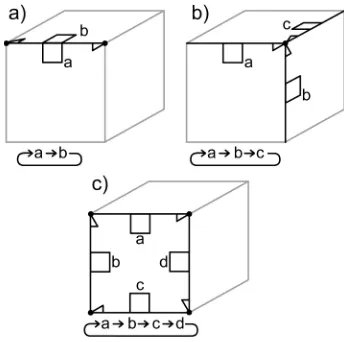
An atomic element used in the construction process is a half-edge which is linked permanently with a dual half-half-edge – they form the DHE element. However, only a full edge consisting of two DHEs is a minimal topological entity that forms a valid model. Thus the full edge consists of four edges. Each half-edge consists of five pointers (see Figure 1): V, S, NV, NF and
D, where: V – a reference to an associated vertex; S – a second half-edge of the full edge; Nv – a next half-edge around a shared
vertex (counter-clockwise (CCW) looking from outside of a cell); NF – a next half-edge around a face (CCW looking from
outside of a cell); and D – a pointer to the dual half-edge. S, Nv
and NF pointers allow for navigation in a 2-manifold cell.
Adjacent cells in a complex are linked by dual edges. Thus additionally the D pointer is used to navigate between cells.
Figure 1. Half-edges in a cell are connected with pointers: a) S – an edge; b) NV – a star; c) NF – a loop; the dual is not shown.
the face. Because all edges in the bundle are connected it can be considered as a radial edge.
Figure 2. Two adjacent cells connected by a dual edge (dashed line) which also represents a shared face (grey); two end points
of the dual edge represent two primal cells.
To guarantee that each face is associated with another, adjacent, face an external cell was introduced – it encloses the whole complex and its volume is infinite. It is necessary in order to provide consistency at the boundary of the model where the cells do not have neighbours on every face.
2.2 Construction operators
The data structure presented in the previous section is on the one hand very simple – there are only edges and vertices – but on the other hand there are many connections between elements and therefore it would be difficult to build a model without a simple construction method. The method proposed in this paper is based on Euler operators. In simple terms, edges and vertices are added one by one until a cell is complete. Then single cells can be linked into a complex, or a cell can be split into two connected cells. It may be sometimes necessary to “prepare” faces before the connection, because two cells can be linked by a shared face only if the faces to be connected have the same number of edges – thus new edges and vertices may be introduced to these faces. In a more restricted version, two cells can be linked only if adjacent faces precisely fit one to another.
The set of Euler operators, including a spanning set and auxiliary operators which are useful in the construction process, is as follows: MEVVFS/KEVVFS – Make/Kill Edge, Vertex, Vertex, Face and Shell; MEVFFS/KEVFFS – Make/Kill Edge, Vertex, Face, Face and Shell; MEV/KEV – Make/Kill Edge and Vertex; MVE/KVE – Make/Kill Vertex and Edge; MZEV/KZEV – Make/Kill Zero-length Edge and Vertex; MEF/KEF – Make/Kill Edge and Face (see Figure 3). The first two operators, a) MEVVFS and b) MEVFFS, need an explanation. They are not typical Euler operators because they introduce: a) an edge, two vertices, a face and a shell (body); b) an edge, a vertex, two faces and a shell. These compound operators consist of two Euler operators: a) MVFS – Make Vertex, Face and Shell and MEV; b) MVFS and MEF. Because the minimal element allowed in a model is an edge, and vertices do not store any topological information, thus MVFS cannot be used (a face cannot be associated with a vertex). In the first construction step MEVVFS or MEVFFS need to be used. (Boguslawski, 2011)
The first construction step (MEVVFS or MEVFFS) creates an internal edge but also associated external edge which forms the external cell. These two primal edges are linked by dual edges bounded by two dual nodes representing internal and external cells in the primal. Additionally, the dual edges form a) two cells where each cell ‘encloses’ one primal node (MEVVFS); b) one cell ‘enclosing’ the only primal node (MEVFFS).
Join/Separate by Face and Merge/Split by Face (see Figure 3) are the only extended operators presented in this paper. Others
like Join/Separate by Edge/Vertex and Merge/Split by Edge/Vertex are not described because they are not used in the proposed method of building modelling. However in a general case two cells can be linked not only by a shared face but also by a shared edge or vertex. Also holes through solids and cavities are not allowed: however, they can be simulated using ‘bridge’ edges – they allow preserving the topological consistency and continuity of a model.
For the sake of clarity the dual structure is not shown in Figure 3 except for the two first operators, where dual edges are represented by dashed lines; the external cell is also included. However, the dual structure and the external cell are modified by all operators.
Figure 3. Euler operators and extended Euler operators.
2.3 Attributes
room name or number can be assigned to a dual node representing the room; a distance between two rooms or a weight used by graph traversal algorithms can be assigned to a dual edge connecting two dual nodes (see Figure 4).
In the example shown in Figure 4, doors are represented as flat cells. Their volume is zero, but still each door has an associated dual vertex. If, for some reason, flat cells are not allowed in the model, then doors can be represented as an attribute assigned to a connection between rooms, e.g. attribute ‘door’ may take two values: ‘yes’ or ‘no’.
Figure 4. Semantic information represented by attributes.
3. BUILDING EXTRUSION
Building extrusion from 2D footprints is one of the simplest methods of 3D city modelling – buildings are represented as basic blocks. However topological consistency should be taken into consideration to avoid block overlapping or duplication – Ledoux and Meijers (2010) proposed the node column approach extrusion method. The algorithm takes as an input a set of polygons, and the result is a set of topologically consistent and valid blocks. Input polygons should be validated first to assure the topological consistency – it is easier to validate a polygon than a 3D object. One of the advantages of the method is that faces shared by adjacent blocks are not multiplied.
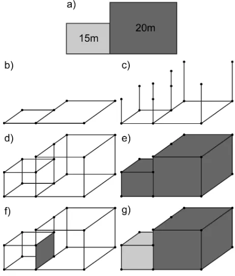
The process of extrusion, using the DHE and the construction method proposed in this paper, can be represented as a sequence of Euler operators. This is based on the node column approach: however some small modifications were introduced. A simple example is shown in Figure 5:
a) A footprint of two building parts of different heights to extrude.
b) In the first step two adjacent polygons are created. Note the shared edge between polygons is not duplicated. A sequence of Euler operators: (the left polygon) MVVFS, MEV×2, MEF, (the right polygon) MEF, MVE×3.
c) All vertices are extruded. Different heights of building parts are taken into consideration when the end points of the shared edge are extruded. A sequence of Euler operators: (the left polygon) MEV×2, (the shared edge) MEV×4, (the right polygon) MEV×3.
d) ‘Roof’ edges are created. A sequence of Euler operators: (the left polygon) MEF×4, (the right polygon) MEF×5.
e) Technically, two building parts are represented as one cell (without a face in between the parts).
f) To split the cell into two parts the Split by Face operator is used. It creates a face between the parts.
g) The result is a complex of connected cells.
This method is suitable for building exterior representation. It can also be used for simple interior modelling – footprints of rooms on all building levels can be extruded to a predefined height which corresponds to the level of the footprints on the next floor. Rooms from different floor can then be linked into a single complex. However, this method is not suitable for complex interiors with sloping walls or intermediate levels within some floors.
Figure 5. Building extrusion from a footprint: a) the footprint; b) two adjacent polygons; c) node extrusion; d) face generation;
e) the building is represented as one polyhedron; f) a new face is added; g) the building is represented as two blocks.
4. CITYGML BUILDING INTERIORS
navigation in the model is available without any geometrical computation.
The resulting models can be enriched with the semantic information included in a CityGML model. For example, attributes assigned to a cell give it a new meaning, e.g. this is a storeroom, or this is meeting room; attributes assigned to a connection between cells can change relations between rooms, e.g. there is a thick wall between rooms – there is no passage, or else the wall is very thin – you can break through in case of an emergency. These attributes can be used in analysis by graph traversal algorithms, since the model has a graph structure.
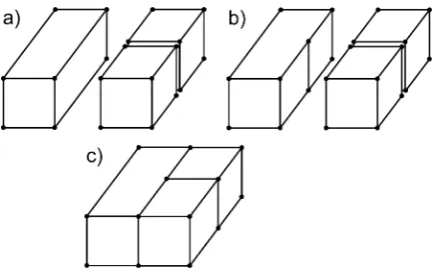
Figure 6. A big room with two smaller rooms sharing a face: a) original rooms; b) splitting a face; c) rooms linked into a
complex.
5. CONCLUSIONS
The DHE is a general data structure that can be used for 3D spatial modelling, including building exterior and interior models. Thanks to the implemented 3D Poincaré duality the number of basic construction entities is limited to two, i.e. edges and nodes – which allows for a straightforward boundary representation. Thus CityGML building models can be easily reconstructed: however, topological relations between the cells forming the model need to be computed, as these relations are not compulsory in CityGML and topology implementation is basic.
The proposed CAD construction method based on Euler operators allows not only changing the geometry, but also provides automatic topology. This is an important property which, together with semantic information described by attributes, makes models suitable for 3D GIS analysis – for example, standard graph traversal algorithms can be readily implemented.
The next planned improvement is to unify 3D buildings with the external terrain, which in CityGML is represented as a 2.5D model. This will broaden the possibility of 3D city model analysis.
Acknowledgement. The research on the DHE data structure was supported by the UK Ordnance Survey and EPSRC funding of a New CASE award.
REFERENCES
Baumgart, B., G., 1975. A polyhedron representation for computer vision, National Computer Conference and Exposition. ACM, Anaheim, California.
Boguslawski, P., 2011. Modelling and Analysing 3D Building Interiors with the Dual Half-Edge Data Structure. PhD Thesis, University of Glamorgan.
Braid, I.C., Hillyard, R.C. and Stroud, I.A., 1980. Stepwise Construction of Polyhedra in Geometric Modelling. In: K.W. Brodlie (Editor), Mathematical Methods in Computer Graphics and Design. Academic Press, pp. 123-141.
Coors, V., 2003. 3D-GIS in networking environments. Computers, Environment and Urban Systems, 27(4): 345-357.
Guibas, L. and Stolfi, J., 1985. Primitives for the manipulation of general subdivisions and the computation of Voronoi Diagrams. ACM Trans. Graph., 4(2): 74-123.
Kolbe, T.H., 2009. Representing and Exchanging 3D City Models with CityGML. In: J. Lee and S. Zlatanova (Editors), 3D Geo-Information Sciences. Springer Berlin Heidelberg, pp. 15-31.
Ledoux, H. and Gold, C.M., 2007. Simultaneous storage of primal and dual three-dimensional subdivisions. Computers, Environment and Urban Systems, 31(4): 393-408.
Ledoux, H. and Meijers, M., 2010. Topologically consistent 3D city models obtained by extrusion. International Journal of Geographical Information Science, In Press.
Lee, J., 2007. A Three-Dimensional Navigable Data Model to Support Emergency Response in Microspatial Built-Environments. Annals of the Association of American Geographers, 97(3): 512 - 529.
Liu, L. and Zlatanova, S., 2012. Towards a 3D network model for indoor navigation. In: Zlatanova, Ledoux, Fendel and Rumor (Editors), Urban and Regional Data Management. UDMS Annual 2011. CRCpress/Taylor and Francis Group, London, pp. 79-92.
Mäntylä, M., 1988. Introduction to Solid Modeling. Computer Science Press, Inc., 401 pp.
Masuda, H., 1993. Topological operators and Boolean operations for complex-based nonmanifold geometric models. Computer-Aided Design, 25(2): 119-129.
Masuda, H., Shimada, K., Numao, M. and Kawabe, S., 1989. A Mathematical Theory and Applications of Non-Manifold Geometric Modeling International Symposium on Advanced Geometric Modeling for Engineering Applications, Berlin, Germany, pp. 89-103.
OGC, 2008. City Geography Markup Language (CityGML) Encoding Standard. Open Geospatial Consortium Inc.
Sheen, D.-P. et al., 2010. Transformation of a thin-walled solid model into a surface model via solid deflation. Computer-Aided Design, 42(8): 720-730.
Tse, R., O. C. and Gold, C., M., 2004. TIN meets CAD: extending the TIN concept in GIS. Future Gener. Comput. Syst., 20(7): 1171-1184.