Development of building fire safety system with automatic security
firm monitoring capability
Wonju Lee
a, Minkyu Cheon
a, Chang-Ho Hyun
b, Mignon Park
a,n aSchool of Electrical and Electronics Engineering, Yonsei University, Seoul, Republic of Korea
bDivision of Electrical Electronic and Control Engineering, Kongju National University, Chungnam, Republic of Korea
a r t i c l e
i n f o
Available online 1 March 2013Keywords:
High-rise residential buildings and their fire safety systems have long been individually designed and constructed according to individual construction plans, rather than planned and efficiently integrated systems. These separate and diverse safety systems have led to elevation of operational training and additional administrative personnel requirements for security firms. Also, alerting other operators of safety events often requires numerous intercom calls. Thus, we propose a new fire safety system to reduce the rates of the false alarms and simultaneously to fight fires using all available operators throughout various departments. This approach is possible because we provide a single command for easily changing the sensor activity values for regular sensor tests and distribute fire messages via LCDs and alarms. This method can eliminate the need for monitoring and intercoms. As a result of the new system, the reaction time to fire emergencies was decreased by 63% compared with systems using existing building automation devices.
&2013 Elsevier Ltd. All rights reserved.
1. Introduction
Security is a serious global issue in the 21st century, partly due to conflicts of religion, racism and ideology. High-rise residential building fires are currently viewed as one of the greatest threats to human life because high residential density increases the likelihood of tragedy[1]. However, the construction of skyscra-pers is inevitable because of population growth and scarcity of living space. Thus, considerable research effort has focused on tracking human locations, as well as identifying the safest and quickest escape routes in buildings[2–4]. These studies are also relevant for escape route planning in the event of fires. Modeling techniques that use mathematical analyses for the design of fire safety systems have been widely studied[5–11]. However, these studies have limited practical use because high-rise residential buildings are designed according to individual construction plans, rather than a single, efficient design. These limitations have led to extremely complex fire safety systems, elevated operational training and additional administrative personnel requirements. It becomes necessary for qualified operators to remain continu-ously on standby in security firms, civil defense organizations and municipalities because of the system monitoring requirements [12,13]. Additionally, a high number of intercom calls makes it
difficult for operators to focus on their work, which increases the likelihood of mistakes [14]. At the subway control center in Daegu, Korea, an urgent intercom call regarding a fire was over-looked because of an overworked operator. Sadly, this oversight led to the deaths of 196 people and the wounding of another 116. This accident demonstrated that the use of an intercom can be fatal when immediate action is required because even a small fire has the capacity for great tragedy[15,16]. This situation does not differ greatly from that of high-rise residential buildings.
Commercialized fire safety systems exist with fire control panels or servers, which take action automatically after a holding time dependent on the severity of the alarm[17]. The holding time is needed for checking for false alarms before the alarm messages goes out to fire stations. This requirement is in place because there can be always false alarms (80% of all alarms are false alarms). Thus, an automatic link to the fire stations should be performed after a certain period of holding time for operators. If there were no holding time, then the fire brigade would come at every false alarm. Hence, we need a new type of fire safety system for solving these problems. To reduce the rates of the false alarms, the new fire safety system must encourage us to test the fire sensors regularly by providing simple commands. The system can thus manage each sensor activity for avoiding the alarm activation during the regular alarm testing. Hence, the proposed system can only send fire messages indicating active alarms to the necessary depart-ments after the alarms have been subject to a filtering service that uses the sensor activity values.
Contents lists available atSciVerse ScienceDirect
journal homepage:www.elsevier.com/locate/firesaf
Fire Safety Journal
0379-7112/$ - see front matter&2013 Elsevier Ltd. All rights reserved. http://dx.doi.org/10.1016/j.firesaf.2013.01.003
n
Corresponding author. Tel.:þ82 2 2123 2868; fax:þ82 2 312 2333.
E-mail addresses:[email protected] (W. Lee),
results. We show fast performance of the proposed fire system by reducing the time required for the confirmation of false alarms or mundane error messages. Finally,Section 6provides our research conclusions, weighing the benefits and drawbacks of the pro-posed fire safety design.
2. Related works
2.1. Building automation devices
Many researchers have studied building monitoring systems, or Building Automation Devices (BADs), such as those digitally connected to fire detectors, brain–heart monitoring sensors and display monitors[18–20]. Such systems are able to identify which fire detector senses a fire because each detector has its own address. Additionally, because the receiver periodically examines the state of each fire detector, it can recognize a breakdown in the system, such as a fire detector failure or an open circuit in the building gateway. However, research regarding network-based security systems for smart building automation has been limited to theoretical studies to date.
Because these systems depend on personnel to monitor them and to call the appropriate emergency personnel to notify them of the situation, these systems are unable to immediately respond to emergencies. Several researchers have proposed security mon-itoring systems managed by qualified operators to watch all of the safety sensors in a number of buildings via geographical informa-tion systems[21–23]. The system can display the exact location of the monitored building and its emergency status in an online map via an internet-based global positioning system. Such features would enable security firms to monitor trouble spots in dense residential areas continuously and to respond swiftly to emer-gency situations or major disasters.
2.2. Operation of existing building automation devices
We must consider the monitoring service to be safety systems’ top priority because they always handle emergencies that require immediate response, such as brain–heart sensors and smoke detectors[24]. Operators in charge of monitoring must continu-ously remain on standby to look for emergency messages from existing BADs connected with several home gateways, which monitor safety sensor statuses. This approach is needed because there can always be false alarms. Typically, however, only a few operators in charge of monitoring actually recognize emergencies when the system receives emergency messages from BADs. Additionally, security firms often have several departments divided into separate assigned roles, such as ventilation fan activation and escape route planning announcements; once an operator notices an emergency message, they must notify all of
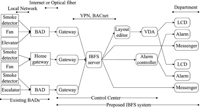
information. As a result, we need to reduce the rates of the false alarms or mundane error messages by a filtering service. The proposed system provides an alert to other operators only for active sensor fire messages by filtering the sensor activity value. These fire messages are distributed by ceiling LCD screens in other departments. Hence, a faster response is made possible by eliminating the delay caused by the need to monitor fire safety devices and to alert other security firm operators by intercom, as shown inFig. 1(b). Consequently, the only remaining steps are identification of the emergency zone and fire station response. Personnel are thus able to swiftly react to fire emergencies because the monitoring and intercom communication steps have been eliminated.
3.2. System architecture applying BACnet
A security firm fire safety system typically consists of a control center and several departments. A control center mainly makes the decisions and gives the necessary departments the control instructions in case of fire. Thus, operators in the departments follow these control center instructions in order to fight the fire simultaneously. For instance, there are a subway operation, electric power, signal and communication department in a typical public subway corporation. The IBFS system control components are thus built into the control center, and the display components are installed in individual departments to follow the current situation closely. In other words, the control center is able to manage departments with control components, such as an IBFS server and alarm controllers. In a similar context, departments receive instructions from the control center via LCD displays and alarms. The structural scheme of the IBFS system is combined with existing BADs by constructing interconnected networks. These existing BADs are comprised of commercialized computer-ized network systems of multiple electronic devices, such as the Integrated Network system 7 (I/NET seven), Apogee and System-600. These components compose a Virtual Private Network (VPN) and communicate through the BACnet.Fig. 2shows the data flow diagram of the proposed IBFS system.
respectively. These objects can be related to each other in a hierarchical and tree-like structure. For instance, the Life Safety Points are always arranged as leaves, while the Life Safety
Zones act as tree nodes. In addition, all Life Safety objects contain properties that represent the audible and visual alarm indicators associated to the entity the object represents. Fig. 1.Fire safety system schematics of (a) existing BADs and (b) the proposed IBFS system.
all LCDs. In addition, the layout editor is also used to adjust the layout of the LCD screen for increased efficiency.
3.3. Maintenance management
The IBFS system has several characteristics for efficient main-tenance management. First, the system provides self-test func-tions for smoke sensors and IBFS components. Operators must perform regular checks and diagnostics to maintain smoke sensors in optimal condition because they are highly sensitive to changes in temperature. The IBFS server has the ability to shut off smoke sensors during testing to ensure that alarms are not activated. Additionally, the server can provide an online diagnos-tic method, such as a periodic ping test, to show quickly the current status of IBFS components in a single view; this method allows effective maintenance and verification of the entire set of IBFS components. The second characteristic of the IBFS system is to provide several management software packages, which provide a graphical user interface for easy system component tracking.
The IBFS server allows easy access to the database; vital data in the database can be accessed even without knowledge of the associated database itself. For example, the Unique Identi-fication (UID) and sensor activities are easily changed with a drop-down menu option provided by the software. An IBFS messenger is used to send urgent messages to other departments and to confirm receipt of fire messages from the IBFS server when an alarm is activated. The IBFS system uses a database, rather than a file system; this approach is used because the system requires secure and exact data processing more than fast access. As a result, operators can easily back up data with internal database functions. This ability means the management software can easily upgrade useful functions provided by the database.3.4. Filtering and scheduling service
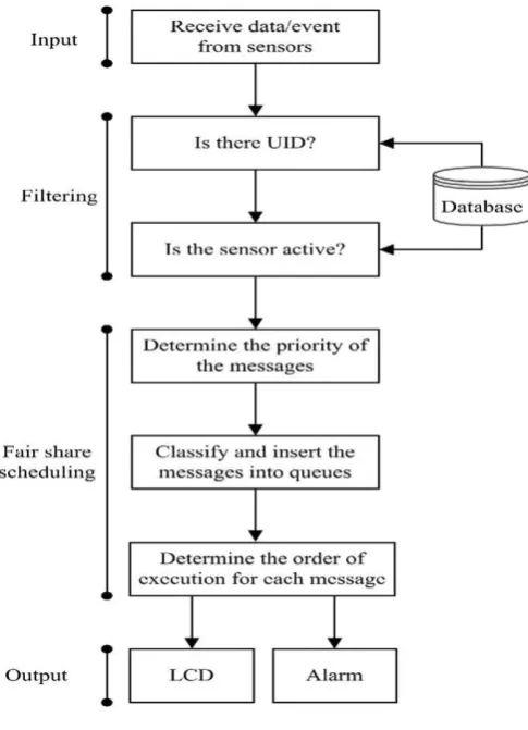
We can think of the proposed IBFS system as the input–output system because the system receives the messages or events from all the various BAD safety sensors and later outputs them via the video and audio indicators. The IBFS system thus collects not only fire messages but also more mundane error messages concerning fans, air conditioners and elevators.
In addition, operators regularly have to test the fire sensors because approximately 80% of fire messages are false alarms caused by temperature change. To avoid alarm activation during alarm testing, the system provides each sensor activity value to
the IBFS server. Based on this value, operators can directly manage each sensor activity in one place, i.e., the control center. To remove the non-fire and inactive sensor messages, the system uses two filtering values: the UID and the sensor activity values. The UID is used to identify fire messages because it includes the fire location (Life Safety Zone object) and alarm information (Life Safety Point object). The sensor activity is used to control whether the fire alarm is activated. Hence, the system can only send the fire messages of active alarms to the scheduling service, as shown inFig. 3. The filtering service however is unable to ensure fast processing of fire messages under high traffic conditions. This limitation is in place because the service simply processes the messages by order of arrival. We thus apply a Fair Share scheduling with a Dual Queues scheme (FSDQ) [28,29]. Alert messages must be classified and inserted into high- and low-priority queues before the scheduler is activated. For exam-ple, fire and other urgent messages are classified as high priority, and all other messages are classified as low priority.
The FSDQ adds each message to one of the two queues, as shown inFig. 4. As a result, the fire message latency time can be decreased by approximately 330% compared to that of a First-In First-Out (FIFO) algorithm; this condition is observed because the latency time of FSDQ is less dependent on the arrival order than a FIFO algorithm is. The processing of fire messages in the high-priority queue is thus expedited.
4. Implementation of the IBFS main components
We implemented the IBFS system, which was composed of several main components. These four main components consisted of the IBFS server, IBFS messengers, IBFS gateways and the layout
editor, which were developed by Visual Studio and executed under Windows XP and Server.
4.1. IBFS server
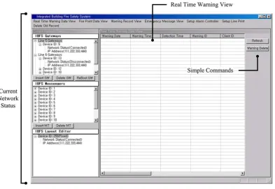
We have already mentioned that the IBFS server can receive fire messages from the IBFS gateways. The server thus filters these messages using the UID and sensor activity values via the internal processing of the IBFS server and later sends them to the display components. To access easily and designate these values for the filtering service, the IBFS server provides several menu options for the user interface: a connection status view, a real-time warning view and a fire point view. These options are closely related to the IBFS database.
We begin by introducing the fire point view. This view always has to include the most recent installation location of each alarm because operators can install an additional alarm at any time. If this view does not include the recent locations of the alarms, then
its fire message is unfortunately ignored by a filtering service. Thus, operators must be careful not to make mistakes with this information and update these data regularly. To modify these data, the server provides several functions: insertion, deletion and modification of fire points. Operators must carefully change the sensor activity values in these data because these sensor activity values are used to avoid the alarm activation during the regular alarm testing. This requirement is in place because the server only sends the fire messages of active alarms to all of the LCDs in other departments. For a quick change, the server provides a single command for changing multiple activity values because operators frequently need to change neighboring alarm activity values.
For safety operation and management, operators always need to always know the current connection status of all of the main components. The server thus provides the current connection status of all components at 2-s intervals via the connection status view, as shown inFig. 5. To modify the monitoring components via this view, operators can insert or delete components using Fig. 4.Comparison of FSDQ with a FIFO algorithm.
name, in alphabetical order. Moreover, the server can also make inquiries as to previous fire messages. However, operators must be careful to query records over long periods of time because large amounts of information can overload the IBFS server, even if the server uses an independent thread.
4.2. IBFS messengers
We show the initial screen of the IBFS messengers, which include an emergency warnings box and a warning information box inFig. 7. Using these boxes, operators can have the ability to confirm the fire warnings and generate emergency messages.
First, the IBFS messengers attempt to connect to the IBFS server automatically after they are initialized in each department. The messengers obtain the current warning information from the
screens to increase the visibility of fire messages via the modifiable screen mode. Thus, operators can change the font styles and positions of the fire messages. Similarly to the IBFS messengers, the layout editor automatically tries to connect to the IBFS server when the layout editor is initialized. Operators can then see current warning information on all of the LCDs via the full screen mode of the layout editor. In other words, this full screen is distributed by the VDAs to alert operators of fire messages. Thus, operators can become aware of real-time fire messages as soon as possible via the LCDs. However, this method may increase the amount of ‘‘burn-in’’ damage to the LCD panels because fire messages are not frequent occurrences. Therefore, the layout editor gives the option to show a moving screensaver, even if it is disconnected from the IBFS server. Next, we will introduce the simple user interface of the IBFS gateways, which is limited to a menu for selecting the types of the BADs. These IBFS gateways receive fire messages from the existing BADs through RS232 ports and transmit them to the IBFS server through LAN ports. In other words, our gateways allow conversion of the formats of fire messages internally via the IBFS gateways. Thus, the gateways only need a simple interface to select the specific formats of each existing BAD. This interface is required because the IBFS system has to integrate with the old BADs, which do not support a standard network protocol, such as the BACnet.
5. Experiment and discussion
5.1. Test Bed installation
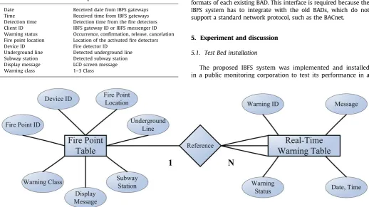
The proposed IBFS system was implemented and installed in a public monitoring corporation to test its performance in a Table 1
Field information of the real-time warning table in a subway corporation.
Field Name Description
Date Received date from IBFS gateways Time Received time from IBFS gateways Detection time Detection time from the fire detectors Client ID IBFS gateway ID or IBFS messenger ID Warning status Occurrence, confirmation, release, cancelation Fire point location Location of the activated fire detectors Device ID Fire detector ID
Underground line Detected underground line Subway station Detected subway station Display message LCD screen message Warning class 1–3 Class
practical application. The corporation had approximately 150 rooms, 14 buildings, 12 departments and 14 BADs used for automated control; we developed one IBFS server using a 2.8-GHz Dual processor, 1 GB RAM and 1000 Ethernet controllers. In addition, we developed 14 IBFS gateways using All-In-One central processing units, which have 100 MHz processors, 256 MB RAM, Ethernet controllers and RS232 ports. These IBFS gateways were configured for each BAD to correspond with the BACnet. Additionally, we developed an alarm controller using a 16-bit micro-processing unit and electronic relays. All of the control components were installed in equipment racks for management efficiency, as shown in Fig. 8. We installed three VDAs (band-width: 270 MHz) with 16 transmitters and 16 receivers to transmit the layout editor screen to 12 LCDs. The transmitters and receivers were installed in the control center and depart-ments, respectively. We also installed twelve IBFS messengers using personal computers in 12 departments to allow simple conversations between departments.Table 2shows the detailed test specifications to which the system was installed in the subway corporation.
The IBFS system was able thus display urgent fire messages via LCDs and generates alarms in 12 departments; these messages
were translated into video and audio signals that were easily seen and heard. However, several issues had to be solved in order to transmit these two signal types clearly. The video signals could not be transmitted over long cables between the control center and the departments: thus, three VDAs and skew-free cables were installed for sufficient amplification and clear distribution, respectively, of video signals. The audio signals, however, were able to be transmitted over 100 feet of cable without a loss in quality. The alarm controller was simply installed to control each individual alarm. In total, the system was able to manage 12 alarms and 12 LCDs with one alarm controller and three VDAs, respectively.
5.2. Evaluation results and discussion
We installed 14 BADs to receive and manage the statuses of sensors in 150 rooms. The BADs always needed a user to check all mundane error messages because the BADs were not only for the fire sensors. However, the IBFS system was able to reduce these error messages that required monitoring or confirmation via the IBFS filtering service. This finding indicated that the system was also able to reduce the rates of false alarms. Hence, for the first Fig. 8.Test bed installation.
experiment, we measured the average number of error messages requiring confirmation using both the BAD and IBFS systems. This experiment also showed the number of eliminated mundane error messages via the IBFS filtering service. We tested the IBFS system and the BAD systems with fire messages based on the following transfer procedures for 7 days to evaluate the efficiency of the proposed system in the test bed.
We were able to theorize that the IBFS system included the procedure for the transfer of the error messages from the BAD to the fire sensors because the BAD was subordinate to the IBFS gateways. Thus, we needed to consider the additional procedures of the IBFS system, as follows. In the event of a fire, the system received fire messages from the BADs through the IBFS gateways using optical communication. The system then transmitted these fire messages to the IBFS server after the IBFS gateways converted them into the BACnet format. To decide whether to include fire messages, the system checked both the UID and sensor activity values in the IBFS database via the IBFS server.
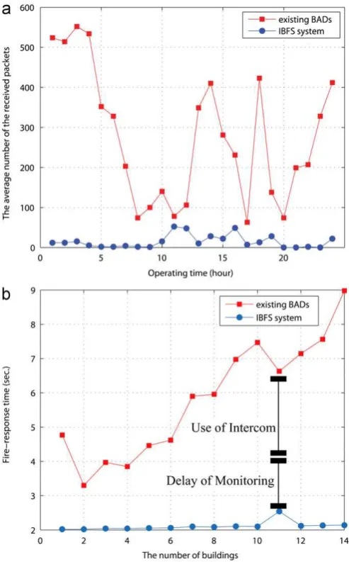
These additional procedures for the integration and filtering of services were automatically processed by the IBFS server using the database.Fig. 9(a) shows that the number of error messages (directly proportional to the monitoring workload) was reduced by approximately 34% via this IBFS filtering service. This experi-ment indicates that the IBFS system does not need more operators for monitoring than the BAD system.
We next measured the average fire-response time, which was taken as the time elapsed from the occurrence of the fire messages to their confirmation by qualified operators. For the second experiment we tested the BAD using the following procedures: 14 operators in charge of monitoring continuously remained on standby to look for fire messages from the BADs. In the event of fire messages, these monitoring operators alerted the other operators of the current emergency situation via the intercom. Thus, monitoring and intercom usage time were pro-portionally increased with the increased number of building rooms and departments, respectively. Fig. 9(b) shows that the fire-response time was increased by approximately 63% using the BAD system. This experiment shows the elapsed time associated with the monitoring and intercom use for the existing BADs.
The second experiment also showed the fast fire-response time using the ISFS system. This increased response time was
O
100–240 V power, 50/60 Hz, operating temperature:þ32 þ1221F Network hub Baseline 10/100 Mbps, Ethernet 24 ports
Alarm controller Atmega32 CPU, max input–output pin: 512, RS-232C, Relay output pin: 16, free voltage input—DC5V
Alarm Operating voltage: 3–24 VDC, min sound pressure level: 90 dB, operating temperature:20 þ601C UTP cable UL List, CATEGORY(CAT 5), 5.5 mm, TIA/EIA-568-A, ISO/IEC 11801, draft category
Skew-free A/V cable UL List, CATEGORY(CAT 5), 5.5 mm, TIA/EIA-568-A, TIA/EIA-568-B
RJ-45 MODULE UL list, CATEGORY(CAT 5), (H: 2.0 cm,W: 2.0 cm,D: 3.1 cm), EIA/TIA 568A, ISO/IEC IS 11801
LCD 22 in.
confirmed by considering the procedures for the following data processing of the ISFS system. From the point of view of the data processing, multiple departments had the ability to respond to fires simultaneously with the IBFS system. This ability was possible because the IBFS server managed a number of BADs and, similar to a broadcasting system, alerted all of the depart-ments to the current situation via LCDs and alarms. Hence, the system was considered to be a distributed processing model; several fire response strategies were able to be implemented at once, such as simultaneous activation of ventilation fans and escape route planning announcements, which further affected the fire-response time. In addition, this experiment also showed the flexible expansion capability of the IBFS system. All that was necessary to monitor an additional building was the insertion of its sensor information into the database via the management software. This modification meant that an additional operator was not required to monitor the new building, leaving the fire-response time of a new building relatively unchanged. In the same context, the system was easily expanded to an additional department by the simple installation of a new LCD and alarm because they were operated by the VDA and alarm controller, respectively. This experiment’s results verified that the IBFS system significantly reduced operator workload by the flexible expansion of the system.
6. Conclusions
In this study, we implemented the IBFS system for fire moni-toring services. The primary contribution of the IBFS system was to help security firm operators focus on their work by eliminating the need for monitoring and intercom use. This improvement was possible because the proposed IBFS system provided a simple scheme for reducing the rates of false alarms by using a filtering service. Additionally, the system provided a VPN and BACnet for structural consistency and cost reduction; the IBFS server was able to receive fire messages from existing BADs and to expedite the processing of fire messages via a scheduling service. The IBFS management software provided the IBFS messenger for simple inter-departmental conversations, easy access to vital data and efficient LCD screen layout management. In addition, the pro-posed IBFS system was easily enhanced and extended to addi-tional service providers, such as home insurance, health-care and other service systems by changing the rules in the filter service. The system was, however, incapable of completely replacing the intercom. Operators still required the ability to speak to one another, even though the system automatically provided fire alarm alerts and provided messengers for simple conversations between departments. In further research efforts, it would be desirable to apply a voice over internet protocol function to the IBFS system.
Acknowledgements
I would like to thank to Ha-Eun Kong for her lovely supports and a beautiful prayer for me. Additionally, I would also like to say thank Jeong-ik Seo ([email protected], A&T) in Republic Korea in for his technical advices.
References
[1] A. Loukaitou-Sideris, B.D. Taylor, C.N.Y. Fink, Rail transit security in an international context: lessons from four cities, Urban Aff. Rev. 41 (6) (2006) 727–748.
[2] L. Chu, A RFID-based hybrid building fire evacuation system on mobile phone, in: Proceedings of Intelligent Information Hiding and Multimedia Signal Processing, 2010, pp. 155–158.
[3] K. Fridolf, D. Nilsson, H. Frantzich, Fire Evacuation in Underground Trans-portation Systems: a Review of Accidents and Empirical Research, Fire Technology 49 (2) (2013) 451–475.
[4] P. Bahl, V.N. Padmanabhan, RADAR: an in-building rf-based user location and tracking system, in: Proceedings of INFOCOM, 2000, pp. 775–784. [5] T. Novak, A. Gerstinger, Safety- and security-critical services in building
automation and control systems, IEEE Trans. Ind. Electron. 57 (11) (2010). [6] P.I. Kaneshiro, E. Villani, P.E. Miyagi, Modeling of fire protection system in
intelligent buildings, Proc. ABCM 2 (2006) 337–344.
[7] P.C. Miclea, W.L. Chow, C. Shen-Wen, L. Junmei, A. Kashef, K. Kang, Interna-tional tunnel fire-safety design practices, J. ASHRAE 49 (8) (2007) 50–60. [8] Z. Liu, A.K. Kim, Review of recent development in fire detection technologies,
J. Fire Prot. Eng. 13 (2) (2003) 129–149.
[9] D.T. Gottuk, M.J. Peatross, R.J. Roby, C.L. Beyler, Advanced fire detection using multi-signature alarm algorithms, Fire Saf. J. 37 (4) (2002) 381–394. [10] B.C. Ko, H.J. Hwang, I.G. Lee, J.Y. Nam, Fire surveillance system using an
omni-directional camera for remote monitoring, in: Proceedings of Computer and Information Technology Workshops, 2008, pp. 427–432.
[11] K.L. Su, Automatic fire detection system using adaptive fusion algorithm for fire fighting robot, in: Proceedings of Systems, Man, and Cybernetics, 2006, pp. 966–971.
[12] A.J. Policastro, S.P. Gordon, The use of technology in preparing subway systems for chemical/biological terrorism, in: Proceedings of Commuter Rail/Rapid Transit, 1999.
[13] Z. Liu, J. Makar, A.K. Kim, Development of fire detection systems in the intelligent building, in: Proceedings of Automatic Fire Detection, 2001. [14] J. Sweeney, Integration of toxic gas monitoring systems into building fire
alarm systems at Harvard University, in: Proceedings of UGIM, 2010, pp. 1–6. [15] H. Liu, L. Gao, S. Li, T. Wu, About automatic fire alarm systems research, in: Proceedings of Information Management and Engineering, 2010, pp. 419–421. [16] W. Suli, L. Ganlai, Automatic fire alarm and fire control linkage system in
intelligent buildings, in: Proceedings of Future Information Technology and Management Engineering, 2010, pp. 321–323.
[17] B. Isler, BACnetTMintegrated danger detection and building control systems, in: Proceedings of Automatic Fire Detection, 2004.
[18] K.C. Lee, H.-H. Lee, Network-based fire-detection system via controller area network for smart home automation, IEEE Trans. Consum. Electron. 50 (4) (2004) 1093–1100.
[19] J.-H. Bae, K.-O. Lee, Y.-Y. Park, An embedded monitoring system for ubiqui-tous network environments, IEEE Trans. Consum. Electron. 52 (2) (2006) 414–420.
[20] K. Balasubramanian, A. Cellatoglu, Analysis of remote control techniques employed in home automation and security systems, IEEE Trans. Consum. Electron. 55 (3) (2009) 1401–1407.
[21] Y. Zhao, Z. Ye, A. Low Cost, GSMGPRS based wireless home security system, IEEE Trans. Consum. Electron. 54 (2) (2008) 567–572.
[22] I.-K. Hwang, J.-W. Baek, Wireless access monitoring and control system based on digital door lock, IEEE Trans. Consum. Electron. 53 (4) (2007) 1724–1730. [23] A.R. Al-Ali, I.A. Zualkernan, A. Lasfer, A. Chreide, H.A. Ouda, GRPS-based distributed home-monitoring using internet-based geographical information system, IEEE Trans. Consum. Electron. 57 (4) (2011) 1688–1694.
[24] E. Chua, W.-C. Fang, Mixed Bio-Signal Lossless, Data compressor for portable brain–heart monitoring systems, IEEE Trans. Consum. Electron. 57 (1) (2011) 267–273.
[25] S.T. Bushby, Integrating fire alarm systems with building automation and control systems, J. Fire Prot. Eng. (2001) 5–11.
[26] W. Kastner, T. Novak, Functional safety in building automation, in: Proceedings of Emerging Technologies & Factory Automation, 2009.
[27] G. Neugschwandtner, W. Kastner, B. Erb, Fire safety alarm transmission in networked building automation systems, in: Proceedings of Factory Com-munication Systems, 2006, pp. 79–82.