Capillary Gripping and Self-Alignment: A Route
Toward Autonomous Heterogeneous Assembly
G. Arutinov, M. Mastrangeli, G. van Heck, P. Lambert, J. M. J. den Toonder, A. Dietzel, and E. C. P. Smits
Abstract—We present a pick-and-place approach driven by capillarity for highly precise and cost-effective assembly of mesoscopic components onto structured substrates. Based on competing liquid bridges, the technology seamlessly combines programmable capillary grasping, handling, and passive releasing with capillary self-alignment of components onto prepatterned assembly sites. The performance of the capillary gripper is illustrated by comparing the measured lifting capillary forces with those predicted by a hydrostatic model of the liquid meniscus. Two component release strategies, based on either axial or shear capillary forces, are discussed and experimentally validated. The release-and-assembly process developed for a continuously moving assembly substrate provides a roll-to-roll-compatible technology for high-resolution and high-throughput component assembly.
Index Terms—Capillary gripper, foil-to-foil integration, liquid
bridge, modeling, moving web, self-alignment.
I. INTRODUCTION
F
OLLOWING a current consumer trend, the demand for high-performance and highly integrated multifunctional systems is expected to further increase in the coming years [1]. Addressing this industrial need eminently requires cost-and time-effective integration of micro- cost-and nanoelectronic components—performing complementary functions such as sensing and actuation, transceiving, power management—onto functional circuitry. Most of these components, however, are subject to mutually conflicting fabrication requirements andManuscript received February 3, 2015; accepted June 29, 2015. Date of pub-lication July 22, 2015; date of current version August 4, 2015. This paper was recommended for publication by Associate Editor Bradley J. Nelson and Editor S. Hirai upon evaluation of the reviewers’ comments. This work was supported by Marie Curie ITN FlexSmell project 238454 and by the Interuniversity At-traction Poles Program (IAP 7/38MicroMAST) initiated by the Belgian Science Policy Office.
G. Arutinov, G van Heck, and E. C. P. Smits are with Holst Centre/TNO, 5656 AE, Eindhoven, The Netherlands (e-mail: [email protected]; [email protected]; [email protected]).
M. Mastrangeli is with the Department of Bio, Electro and Mechanical Sys-tems, ´Ecole Polytechnique, Universit´e Libre de Bruxelles, Bruxelles 1050, Bel-gium; he is currently with the Physical Intelligence Department of the Max Planck Institute for Intelligent Systems, Heisenbergstr. 3, 70569 Suttgart, Ger-many (e-mail: [email protected]).
P. Lambert is with the Department of Bio, Electro and Mechanical Sys-tems, ´Ecole Polytechnique, Universit´e Libre de Bruxelles, Bruxelles 1050, Bel-gium (e-mail: [email protected]).
J. M. J. den Toonder is with the Department of Mechanical Engineering, Eind-hoven University of Technology, EindEind-hoven 5600 MB, The Netherlands (e-mail: [email protected]).
A. Dietzel is with the Institute of Microtechnology, Technical University of Braunschweig, Braunschweig 38124, Germany (e-mail: a.dietzel@tu-brauns chweig.de).
This paper has supplementary downloadable material available at http:// ieeexplore.ieee.org.
Color versions of one or more of the figures in this paper are available online at http://ieeexplore.ieee.org.
Digital Object Identifier 10.1109/TRO.2015.2452775
processing constraints. This makes purely monolithic integra-tion demanding [2]. Heterogeneous integraintegra-tion onto a carrier substrate is, therefore, regarded as a promising alternative [3]. Advanced devices benefiting from hybrid integration of sep-arately manufactured subsystems include, among others, ra-diofrequency communication units [4], addressable sensor ar-rays, and light-emitting diodes [5].
Assembly of components onto preprocessed substrates such as printed circuit boards or back-end-of-line processed sili-con wafers relies on the accurate registration of the compo-nents onto predefined assembly sites. The operation involves fetching, grasping, positioning, and releasing components. This consistent set of actions is commonly performed by robotic effectors equipped with force feedback and gripping tools [6] to specifically handle components of centimetric down to micro-metric sizes [7]. A variety of gripping principles and methods have been demonstrated [8]–[11], including contactless han-dling techniques [12]–[14]. Nevertheless, most conventional mechanical grippers operate in direct contact mode and in the absence of compliance the force they exert may damage delicate components [8]. By subsuming compliant component grasp-ing, component self-centergrasp-ing, and favorable force versus size scaling [15], capillary gripping represents a nonintrusive ma-nipulation technique of choice for a large range of component assembly tasks.
A capillary gripper is a robotic end effector handling a liquid droplet at its active extremity. The gripper touches an approach-ing component indirectly through the droplet. Upon contact, the droplet establishes a liquid bridge between gripper and compo-nent. The compliance of the droplet avoids imparting excessive shocks to the components, and by a tailored wetting action, the droplet can reliably grasp objects even with rough and warped surfaces. The axial force ensuing from confined liquid bridges allows lifting components weighting up to tens of milligrams [6]. Even for relatively high accelerations, and in absence of ad-ditional constraints for component release, the capillary lifting force can prevail over the apparent component weight.
Concerning component release, the variety of strategies avail-able can be generally categorized as passive or active [6]. Passive release strategies exploit environmental conditions like surface features to reduce adhesive forces between gripper and compo-nent [16]–[20]. Active release strategies employ specific gripper actions [10], notably the modification of gripper curvature [21], change of meniscus pressure by gas injection [22]. We previ-ously reported an integration process based on topographical surface structuring via laser patterning for accurate capillary self-alignment of plastic electronic devices [23]. In that ro-bust but manual process, foil dies were coarsely superposed onto water-coated assembly sites by means of vacuum
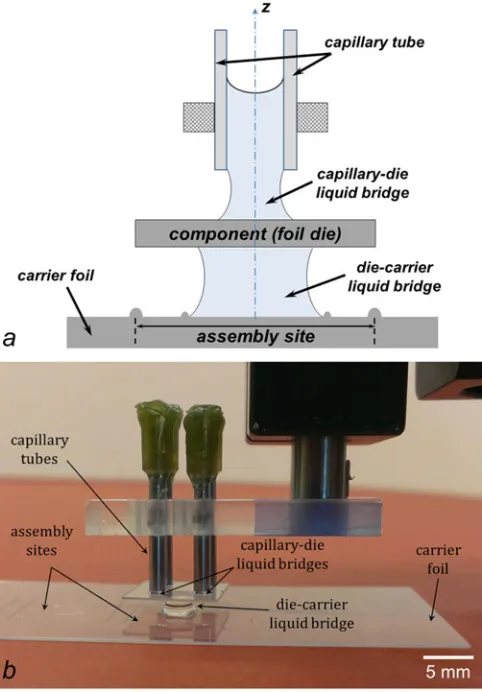
Fig. 1. Sketch of the sequential process steps for component-to-substrate integration (exemplified as foil die-to-foil carrier integration in this study) by capillary gripping and self-alignment: (1) water-filled capillary tube (i.e., the capillary gripper) approaching the foil die, (2) formation of the capillary-die liquid bridge by sealing of the bottom end of the capillary, (3) vertical lifting of the foil die by retraction of the capillary, (4) patterning of the assembly site on the carrier substrate, and controlled water dispensing within the inner confining ring, (5) coarse prealignment of the foil die over the site, and formation of the die-carrier liquid bridge, (6) release of the foil die from the gripper, and (7) constrained self-alignment on the assembly site.
ers before accurately self-aligning through capillarity and shape matching.
In this paper, we introduce and characterize a component-to-substrate integration concept based on the seamless combination of capillarity-driven component gripping, passive release, and self-alignment onto structured substrate sites. The process ex-ploits competing liquid bridges [19]–[20] to autonomously align mesoscopic components onto prepatterned substrates (see Fig. 1). The gripper is composed of several capillaries, i.e., cylindrical liquid-filled tubes with both ends open and attached to a programmable and remotely controlled motion stage (see Fig. 2). The integration process only requires coarse alignment steps, both to bring the gripper into contact with the component and, subsequently, to bring the component in contact with a liquid droplet confined on the substrate. Furthermore, the com-bination of capillary gripping with a novel dynamic shear release technique enables an assembly process with superior through-put and accuracy and opens a solid route toward autonomous and highly reliable roll-to-roll component integration.
II. CAPILLARYGRIPPING ANDSELF-ALIGNMENT
A. Experimental Procedure
The assembly process presented in this study (see Fig. 1) re-lies on the consistent combination of individually well-mastered techniques: topographic surface structuring, capillary gripping, competing liquid bridges, and capillary self-alignment [24]. Through the process, a generic target substrate can be efficiently populated with components of known footprint.
First, the substrate is structured to support the self-alignment process. Two sets of trenches were laser-scribed in a 125-µ m-thick Polyethylene Naphthalate (PEN) foil substrate (Teonex Q65FA, Teijin DuPont) [23] using a Coherent AVIA 355 nm, 25-ns Nd:YAG laser source in combination with a galvano-scanner: deep outer trenches defining the assembly sites and shallower inner circular trenches to precisely confine a single liquid droplet in the center of each site. Foil dies mimicking cen-timetric components were similarly laser-machined from
trans-Fig. 2. Competing liquid bridges for capillary component gripping and passive release to a substrate. (a) Component held between the capillary-die (top) and die-carrier (bottom) liquid bridges (sketch not to scale). (b) Implementation of the capillary system for foil-to-foil integration.
parent 250-µm-thick PEN sheets to exactly match the geometry of the assembly sites. Joint markers were scribed onto the foil dies and the assembly sites to provide a quantitative measure of the alignment accuracy. Fabrication details can be found in a previous publication [23].
The assembly process starts by dispensing a water droplet within the inner trench of each assembly site. The confined droplet of known volume assumes thereby a predictable profile [23]. The wettability of the top surface of the foil dies was in-creased through an oxygen plasma treatment (400 W for 1 min) that decreased the static water contact angle (from65◦±3 to
8◦±2) and improved adhesion with the gripper. The same
sur-face treatment can similarly increase the forces exerted by the assembly substrate during capillary self-alignment [25]. This was, however, omitted, as it was found to inhibit droplet con-finement and correct component registration [23].
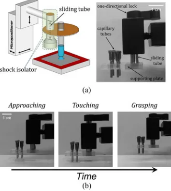
Fig. 3. (a) Schematic representation (not to scale) and side view of the capil-lary gripper with shock isolator lock used to reduce the impulsive forces exerted on components. (b) Timeframe showing the grasping sequence of the capillary gripper. The gripper approaches vertically the foil die (left), until it establishes contact with it and the shock isolator glides up (middle). Hence, the foil die is grasped, the gripper is pulled off, and the shock insulator glides down (right).
capillary-dieliquid bridge (see Fig. 2). The component can then be lifted upon vertical retraction (i.e., pull-off) of the gripper.
By bringing the foil die into contact with the droplet rest-ing on an assembly site, adie-carrierliquid bridge is formed (see Fig. 2). As the water spreads over the confining surfaces, the axial force exerted by the die-carrier liquid bridge gradu-ally increases. When this force exceeds that of the competing capillary-die liquid bridge, the latter collapses releasing the foil die from the gripper. Henceforth, the die self-aligns onto its matching assembly site driven by the constrained relaxation of the underlying liquid meniscus [26].
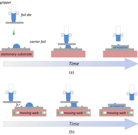
Contact of the foil die with the confined droplet could be ini-tiated in various ways, each yielding a specific release method. In particular, either the substrate or the gripper can be in motion, and component release can be initiated eitherverticallyor hor-izontally(i.e., bylateral shear). In vertical release, the gripper lowers the component onto the droplet from above. Horizontal component release is conversely enacted as the gripper trans-lates the component laterally and slides it into contact with the droplet at a controlled distance from the substrate. Both methods will be described in more detail below.
B. Realization of the Capillary Gripper
The component capture range of a capillary tube is set by the vertical protrusion of the inner liquid from its bottom end. In the limit of submillimetric droplets, accurate positioning and/or force feedback are typically employed to avoid potentially dam-aging impacts between gripper and components. A prior gripper had a water-filled glass capillary whose push–pull action de-formed the protruding water drop to change the working range of the gripper [27]. We developed a compliant capillary gripper by using a shock insulator lock (formed by a sliding piston; see Fig. 3). The capillary of the gripper is suspended by the shock
insulator, which glides upwards when in contact with an object
[see Fig. 3(a)]. This way, the grasped component experiences the mechanical impact exerted solely by the cumulative weight of capillary and supporting piston mechanism, amounting to a few millinewtons only, rather than that of the complete gripping stage (see Fig. 3). The compliant contact with the component surface compensates for the limited capture range of the hang-ing droplets. Thanks to this, the gripper merely requires coarse motion driving. The soft contact between capillary and compo-nent also enforces wetting and the repeatable formation of the capillary-die liquid bridge.
The complete capillary gripper system consists of four nom-inally identical capillaries arranged to span the four corners of the foil dies. This organization prevents uncompensated torques and consequent tilting of the dies upon pull-off of the gripper and enhances the stability of the operation.
III. ANALYSIS OF THECAPILLARYGRIPPER
A. Capillary Lifting Force
A critical parameter for the gripping operation integral to the assembly process is the lifting force the capillary gripper can exert. The lifting force determines the limit weight of the components that can be handled and the accelerations they may be safely subjected to during handling.
To raise a component of massmdiefrom a supporting surface, the lifting capillary forceFC needs to overcome the sum of the
component weightFG =mdieg(gis the acceleration of gravity) and the (noncapillary) adhesion forceFA between component
and resting surface. Since the accelerations imparted by our gripper on the component (a few mm/s2at maximum) are≪g, the grasping condition is defined by
FC > mdieg+FA (z= 0). (1)
During component handling, the dynamic condition
FC > mdiea (z >0) (2)
withabeing the cumulative component acceleration, enforces avoidance of break-up of the capillary-die liquid bridge. As described below, the lifting force exerted by the capillary gripper was measured experimentally, and the gripping operation was simultaneously video-recorded to track the evolution in time of the geometry of the capillary-die liquid bridge, defined in Fig. 4. A hydrostatic model was developed to frame the lifting force exerted by the open-ended capillary gripper.
1) Lifting Force of the Capillary Gripper: The lifting force exerted by metallic capillaries of different radii R (0.41, 0.83, and 0.92 mm, respectively) was measured experimen-tally through the setup sketched in Fig. 5(a) (and detailed in the Appendix). A foil die was fixed to a precision electronic bal-ance, and a side-view high-resolution camera in-siturecorded the shape of the capillary-die liquid bridge. A positioning base stage holding the shock insulator lock was used to bring a single water-filled capillary in contact with the top foil die surface. By pulling up the gripper at a speedvpu = 10µm/s, the protruding
Fig. 4. Free-body diagram (not to scale) of a foil die resting onto a carrier and in contact with the gripper through the axisymmetric capillary-die liquid bridge. Relevant geometrical parameters of the capillary gripper are indicated.
For all capillaries tested, we recorded an initial increase of lifting force with increasing gap up to a maximum, after which the lifting force decreased with further increase of the gap, until pinch-off of the liquid bridge occurred [see Fig. 5(b)]. Wider capillaries exerted larger maximum lifting forcesFm ax, which scaled with the square of their radius [i.e., meniscus contact area; see Fig. 5(c)]. Unnoticeable differences in the force ver-sus gap curves were observed when varying vpu within the
experimentally range of 1 µm/s up to 50 mm/s. The shape of a liquid bridge has a characteristic response rate propor-tional to the capillary velocity vcap =γ/η, i.e., the ratio of surface tensionγ and viscosity η of the liquid [28], amount-ing toࣈ73 m/s for a water/air interface at room temperature. Hence, νpu ≪νcap in all cases, and the axial stretching was quasi-static.
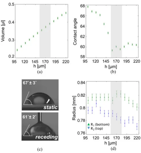
Relevant geometrical parameters of the liquid bridge were estimated from postprocessing of the recorded frames. Fig. 6 shows experimental data for a capillary with R of 0.83 mm. Contrary to standard capillary grippers, in our case, the volume of the capillary-die liquid bridge is notconstant, and instead, it increases with the gap[see Fig. 6(a)]. As the gap increases, gravity and negative Laplace pressure pull water from inside the capillary (of 16µL volume) into the bridge. The downward water flow is made possible by the additional water/air interface present at the open top end of the capillary. Moreover, during pull-off, the triple contact line of the meniscus remains pinned on the lower surface, and its contact area remains constant, as long as the contact angleθ1is larger than its receding valueθ1r [see Fig. 6(b)]. Upon further stretching of the bridge, the bottom contact angle reachesθ1r[see Fig 6(c)]; henceforth, the contact
line unpins and the contact radiusR1 is observed to decrease
[see Fig. 6(d)]with rather constantθ1[see Fig 6(b)]. As the gap continues to increase, the liquid bridge thins down and finally
Fig. 5. (a) Schematic representation of the measurement setup for the lifting force exerted by a capillary gripper and the shape of the capillary-die liquid bridge, using an electronic balance and a side-view camera. (b) Lifting force generated by a capillary gripper as a function of gap height. (c) Maximum lifting forceFm a xversusR2(square radius of the capillary tube). Note that, since the neck radius of the liquid bridge is smaller thanRwhenFm a x is exerted, the regression does not extrapolate toR2→0.
Fig. 6. (a) VolumeVof the liquid bridge versus gap heighth. (b) Bottom contact angleθ1 of the liquid bridge as function ofh. (c) Staticθand receding θrcontact angles of water on PEN foil. (d) Contact radii of the liquid bridge:
pinches off at its neck, leaving a small droplet on the surface of the foil die after breakup. The rupture of the meniscus occurs at different elongations depending on the radius of the capillary
[see Fig. 5(b)]. For the widest capillary (R= 0.92mm), forces up to∼0.7 mN (corresponding to 70 mg of apparent weight) could be generated[see Fig. 5(b)]. By combining multiple cap-illaries into the gripper, the lifting force can be adapted to the user’s needs.
2) Analytic Model of the Capillary Gripper: We derived an analytic model of the capillary gripper to obtain an accurate reconstruction of the geometrical profile of the liquid menis-cus, and from that, an estimate of the capillary lifting force was benchmarked with the experimental data. We particularly aimed at understanding and quantifying the specific role of the additional water/air interface of the top open end in the grip-per grip-performance (refer to the geometry of Fig. 4). With respect to prior models of liquid menisci bridging a vertically moving tip of finite width to an infinite planar substrate [29], [30], our model assumes that the volume of the meniscusV(which does not include that of water inside the capillary) isnota conserved quantity, rather it can increase as function of the gap[as observed in Fig. 6(a)].
The model is quasi-static, consistent with the dynamics of axial stretching described in the previous section. It reconstructs the geometryr(z)of the capillary-die water meniscus, and from that the axial force applied by the gripper on the component, for a given gap heighth. A force-versus-time profile of the gripping action can be obtained from the knowledge of the time sequence of the gap values. All parameters of the geometry could be obtained from the experiments, with the exception of the contact angleθ0of the liquid on the inner capillary surface, which could not be visualized in real time because opaque metallic capillaries were used in the reference experiment.
The profiler(z)of the water meniscus is reconstructed from the axisymmetric Laplace equation [15] as
∆p(z) This second-order nonlinear differential equation (3) can be solved by positing (′indicates derivative with respect toz) as
Y=
thus obtainingr(z)from the following system of first-order dif-ferential equations:
complemented by the boundary conditions
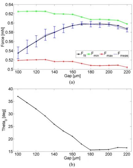
Fig. 7. Total capillary lifting force versus gap height for an open-ended cap-illary of 0.83 mm onto a PEN foil.Fm e a sis the experimentally measured value (mean and standard deviation).Fm inandFm a xare the forces predicted by the model for an interfacial profile at the open end of the capillary set by constant, minimum and maximumθ0 values of 10°and 40°, respectively.Ffi t is the total capillary force predicted usingθ0 as fitting parameter of the model. The corresponding values ofθ0are represented in (b).
where
is the pressure jump across the interface at the top open end of the capillary (ςbeing its radius of curvature),pin(z)andpatmthe pressure inside the capillary and in the atmosphere, respectively, andzm is the total height of the water column. Hence
∆p(z) =ρg(zm −z)−2cosRθ0γ
= ρgzm −2cosRθ0γ−
=f(θ0, ρ, V)−ρgz.
(9)
The set of (5) was solved forr(z)through MATLAB’s ode45 routine using (9) and the boundary conditions in (6). The solu-tion was accepted when the reconstructed value ofR2 =r|z=h
coincided with its measured value within a relative error of 10−5. A self-consistent loop was implemented to determine the value of zm for eachh from the knowledge ofV and of the
recon-structed volume of the meniscus. The total lifting force of the gripper was calculated as the sum of the terms dependent on Laplace pressure and surface tension [15]:
Ftot(h) =πR21(h)·∆p|z= 0+ 2πR1(h)γsinθ1(h). (10)
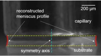
Fig. 8. Profile of capillary-die liquid bridge reconstructed by the model and superposed onto a video frame of the reference experiment (h= 180 µm,
R= 830µm,R1= 822µm,R2 = 785µm,θ0= 15.5).
Fig. 7 provides a comparison between the predicted and the measured maximal gripping forces for the 0.83-mm radius cap-illary as a function of the gaph. In absence of experimental data, the water contact angle at the open end of the capillary θ0(t) was used as free model parameter. Along with the force profile predicted by fittingθ0,in Fig. 7(a) for each value ofh, we also show the numerical predictions of the force for two limiting and constant values of θ0 (10°and 40°, respectively) that can encompass the measured values of the gripping force. The fitted values ofθ0(t),presented in Fig. 7(b), are consistent with an interpretation based on the deformation (at constant position) and subsequent receding motion (at constant contact angle) of the water contact line at the top water/air interface, analogous to that ofθ1(t)shown in Fig. 6(b). A numerical reconstruction of the meniscus profile is shown in Fig. 8.
The model can capture the physics of the experiment and quantitatively reproduce the experimental force data. The con-tact angleθ0seems to play an important role in the modulation of the lifting capillary force. Its active use to control grasping and release operations, for instance through electrowetting, can be envisioned and is left for future investigations.
B. Adhesion of Foil Dies to Supports
The adhesion of components to their supporting surfaces, arising from possible interactions such as van der Waals forces, electrostatic and pressure imbalances during the lifting action, was found to play a nonnegligible role in determining the re-quired pick-up force [9], [31]. We phenomenologically describe the cumulative adhesion force asFA =β·l2for a foil die of side
lengthl, withβbeing a dimensional constant. Hence
FC =mdieg+FA =αl2g +βl2 = (αg+β)l2 (11)
whereα= 0.36 mg/mm2 is the mass density of the PEN foil die (of constant thickness), and the sizelm ax of the largest foil die liftable by the maximum grasping forceFm ax[see Fig. 5(b)] is
lm ax =
Fm ax
(αg+β). (12)
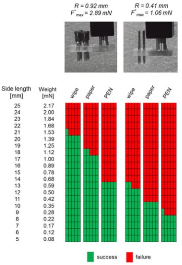
To quantify the adhesion force, square-shaped foil dies rang-ing in side length from 5 up to 25 mm were gripped from three surfaces differing in the degree of porosity and roughness mod-ulating the contact area with the die: soft cleanroom wipe made from polyester knit fabric (Super Polx1200, Berkshire), paper (Black Label Zero, 80 g/m2, Canon), and PEN foil. The gripper
Fig. 9. Grasping of foil dies with the capillary grippers from different surface types and using two homogeneous sets of capillary tube (radii and maximum lifting forces indicated in the insets). From each surface type, a foil of each size was gripped five times with pull-off velocity of 10µm/s.
with four capillaries was used, and two sets of capillaries (radii of 0.92 and 0.41 mm) were tested. For each surface type, the various foil dies were gripped five times at a pull-off velocity of 10µm/s. A correlation between maximum pulled load and type of support surface was observed (see Figs. 9 and 15). Larger foil dies could be gripped from porous wipes while not from the PEN foil. The adhesion force density for the three different sur-faces was estimated to range from 3.5µN/mm2for cleanroom wipes to 13.6µN/mm2for PEN foil. Using porous noncharged surfaces such as the wipes considerably reduced the required lifting forces and extended the gripping process window.
C. Release and Self-Alignment
The component release strategies we propose exploit the for-mation of the die-carrier liquid bridge to grasp a foil die sus-pended by the capillary-die bridge (see Fig. 2 and step 6 in Fig. 1). Not only is such bottom liquid bridge designed to pre-vail over the top capillary-die bridge, it is also the medium itself driving the capillary self-alignment of the component on its matching assembly site. The release of the component seam-lessly coincides with the inception of its self-alignment.
The release condition is, therefore,
FC < mdieg+FBot (13)
whereFBot is the axial capillary force exerted by the bottom liquid bridge. As previously shown, the capillary gripping force FC has a maximum value approximately proportional to the
cross section of the capillaries. Conversely, the axial force of the die-carrier liquid bridge increases monotonously in time, because the cross section of the liquid bridge constantly and rapidly grows upon formation to ultimately encompass the full bottom surface of the die [23]. Since this surface is by design considerably larger than that of the capillaries, the grasping force exerted by the die-carrier bridge will rapidly become dominant, ensuring reliable component release.
Fig. 10. (a) Sketch of a foil die brought in contact with a droplet confined in the center of an assembly site. (b) Top view of the foil/water interface created immediately upon contact of the foil die with the droplet. (c) 12.5-µL water droplet preconfined within the inner circular trench onto a carrier foil and (d) corresponding self-alignment of a shape-matching 10×10 mm2foil die.
[see Fig. 10(d)]. The foil die held by a micropositioner was coarsely superposed onto the assembly site and then lowered to precisely contact the confined droplet and form a die-substrate liquid bridge at a gap height h∗ of 0.8 mm [see Fig. 10(a)]. As a result, a circular water/PEN interface with radiusRb ot =
1.55mm formed instantaneously on the bottom surface of the foil die[see Fig. 10(b)], yielding an estimated initialFBot of
∼1.8 mN, which grew up to∼20 mN when after few millisec-onds the meniscus spread to cover the entire surface. From the above results, we could tune the force involved in the carrier-die liquid bridge with respect to the capillary-die liquid bridge to optimize the both pick-up and release of the foil dies.
To confirm our modeling of all relevant aspects of the pro-cess, we set 10×10 mm2 foil dies (weight of 0.35 mN) on a cleanroom wipe (adhesion force of 0.7 mN). The minimal force required by the gripper to pick up the foil dies was thus estimated to be∼1.05 mN. Four glass capillaries fabricated from Pasteur pipettes (Wu Mainz, Germany; radius of 0.65 mm) were chosen for the gripper, resulting in a capillary gripping force around
∼1.74 mN. Next, the foil dies were prealigned with a corre-sponding assembly site, lowered down to∼0.8 mm above the carrier substrate and brought into contact with the droplet. Pas-sive release and ensuing self-alignment of the foil dies was then observed as expected, given the previously estimated value of FBot (1.8 mN). The experiments were repeated over 15 times with no assembly failure[see Fig. 10(d)].
D. Release Strategies
1) Vertical Component Release: In conventional pick-and-place assembly [23], components are assembled onto assembly sites predefined overstationaryassembly substrates. Such ver-tical release strategy was hereby mimicked and studied, as de-scribed in the previous sections, by keeping a prepatterned foil substrate fixed while the capillary gripper was grasping, moving, and releasing the foil die[see Figs. 1 and 11(a)].
2) Horizontal Component Release: The fast and reliable release dynamics afforded by the die-carrier liquid bridge prompted an alternative release strategy based on a shearing capillary action. This novel distinctive release technique is
com-Fig. 11. Schematic side view of the two alternative, passive capillary strategies for component release: 1) release by vertical capillary forces on stationary carrier, and 2) dynamic shear release by lateral capillary forces on moving web.
Fig. 12. Platform used to demonstrate the assembly processes. The capillary gripper is connected through the shock insulator to thez-stage. Foil dies are placed onto a cleanroom wipe. A water reservoir is provided at the back to fill the capillaries. A carrier assembly foil with assembly sites is placed in the front. one-millimeter-high water droplets are confined in the circular trenches. A positioning stage is used to perform all lateral movements.
patible with system integration by capillary self-alignment onto
movingsubstrates, i.e., a continuously moving automatic assem-bly line[see Fig. 11(b)]. The process proceeds similarly to that of the vertical die release as far as substrate patterning, droplet dispensing, and component grasping are concerned (steps 1–5 of Fig. 1). Then, the foil die is suspended at a specific height
h∗lower than the bottom droplet’s height. This way, the droplet moving with the substrate will intercept the foil die. Upon con-tact between the foil die and the droplet confined on the assembly foil, the die-carrier bridge forms within milliseconds and the die is automatically grasped. Given the relatively high speed ofࣈ
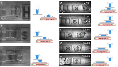
Fig. 13. Video frames and corresponding schematic representation of the vertical release and self-alignment of a 10×10 mm2foil die (case of letter “t”; see Supplementary Material for the video of all 11 foil dies). (a) Gripper is coarsely aligned over its assembly site. (b) Gripper is lowered to approximately 0.8 mm above the surface, touching the water droplet and forming the carrier-die liquid bridge. (c) Passive release of the foil die from the capillary gripper. (d) High-precision self-alignment of the foil die onto carrier foil as the droplet wets the whole assembly site. The inset shows a high-resolution micrograph of the matching of the alignment markers on the substrate and on the foil die after self-alignment.
Fig. 14. Overviews, side views, and corresponding schematic representations of shear capillary release and self-alignment process on a moving web of a 10×10 mm2foil die (case of letter “t”; see Supplementary Material for the video of all 11 foil dies). (a) Foil die lowered by the gripper to the preset heighth∗. (b)
Such adynamic shear releasetechnique is minimalistic, au-tonomous, nontriggered, and programmable, thus greatly bene-ficial for the scalability and throughput of the integration pro-cess. Since the release merely relies on the contact of the bottom moving droplet with the suspended foil die, the foil dies can be held above the web for an arbitrary period of time ready for assembly. Release will only be initiated once a droplet slides underneath the suspended foil dies. Provided that the thickness of the components is smaller than the initial height of the con-fined droplets, the passive grasping and release process is not frustrated by components already assembled on the substrate, and it can be programmed to smoothly populate the entire sub-strate. By the same token, multiple grippers, each holding a component, could be set simultaneously along the main web axis to pipeline the assembly process.
IV. DEMONSTRATOR
To provide a comprehensive verification, the aforementioned all-capillary assembly processes with the two release methods were tested to self-align 11 dummy 10×10 mm2foil dies, each weighting 0.35 mN and marked with a letter spelling “Holst Centre.” The system used for the demonstration consisted of a moving stage, the capillary gripper, the foil dies, the assembly substrate with scribed trenches and confined water droplets, and a water reservoir. The foil dies were placed by hand onto a wipe at a pitch of 15 mm in the same order as they would be assembled on the carrier substrate. The capillary gripper with the shock insulator lock was fixed to az-axis stage so that it could be moved up during stage translations and down during grapping and releasing. The gripper was realized with four glass capillaries. An overview of the platform is shown in Fig. 12.
Two cameras recorded the overview and side (close-up) view of the assembly process. A high-resolution microscope camera was used to inspect alignment precision after foil die assem-bly on the carrier foil. The full video of the assemassem-bly process (provided inSupplementary Information) demonstrates how the strategy was used to accurately and reliably pick and place the foil dies using the vertical release strategy. Excerpts are given in Fig. 13. Fig 13(a) shows a skewed foil die held over the assembly site by the capillary gripper. The foil die is then lowered to∼0.8 mm above the substrate to come into contact with the droplet[see Fig. 13(b)]; then, the gripper is raised by 1 cm[see Fig 13(c)], while the die is released from the gripper through the carrier-die liquid bridge and self-aligns with respect to the outer scribed trenches[see Fig. 13(d)]. The accuracy of the alignment, quantified through the laser-scribed markers[ in-set of Fig. 13(d)], was∼20µm, a figure consistent with the accuracy of the laser scribing process [23]. The procedure was successfully repeated for all foil dies.
The shear release strategy was demonstrated analogously, the key difference being that the assembly on a moving web was simulated by picking up each foil die with the gripper and translating the gripper in front of the line of the preset assembly sites, as shown in Fig. 14(a). The capillary gripper held the foil dies approximately 0.8 mm above the assembly substrate, while the stage moved the assembly sites at a predefined velocity of 80 mm/s. In Fig. 14, the letter “t” is assembled to spell the word “Holst.” Fig. 14(a)–(c) show how the suspended foil
Fig. 15. Success chart for lifting of foil dies from different surfaces through the two capillary grippers. From each surface type, one foil of each size was gripped five times with pull-off velocity of 10µm/s.
die passes above the previously assembled foil dies, until the die comes into contact at full velocity with the droplet of the first available assembly site. Upon contact of the foil die with the preconfined droplet, the die-carrier liquid bridge is seen to immediately form and release the foil die from the grasp of the capillary gripper[see Fig. 14(d)]. The released foil die, now connected through the liquid bridge to the moving carrier substrate, slightly overshoots its corresponding assembly site due to its inertia [see Fig. 14(d)–(h)]. The capillary restoring force of the laterally stretched meniscus in turn exerts a shear stress that pulls the foil die backwards. The die undergoes self-alignment and finally aligns with high precision[∼20µm, inset in Fig. 14(h)]onto its assembly site. A video recording of the full process can be found in the “Supplementary Information.”
V. CONCLUSION
of dies onto continuously moving substrates. Prospects of a par-allelized, autonomous, and continuous roll-to-roll assembly line make it an advantageous mass production approach.
APPENDIX
MATERIALS ANDMETHODS
A. Foil Dies and Carriers
PEN (Teonex Q65FA, Teijin DuPont) was used as base ma-terial. 125-µm-thick foil substrates and 250-µm-thick foil dies were, respectively, patterned and ablated using a Coherent AVIA 355 nm, 25-ns Nd:YAG laser source in combination with a gal-vano scanner. Static and receding water contact angles on the foil surfaces were measured through the static and contraction sessile drop methods, respectively (EasyDrop, KR ¨USS).
B. Capillary Gripper
The gripper featured cylindrical tubes fixed onto a lightweight 3-mm polymethyl methacrylate supporting plate, attached to the positioning stage through a one-directional locking mechanism (see Fig. 3). The capillaries were fabricated from precision stain-less steel dispense tips (Nordson EDF) consisting of an open metal tube attached to a polypropylene leur lock connector.
C. Measurement Setup
The three-axis motion system was made of an in-plane po-sitioning stage (Newport MM4006) combined with a vertical motion stage (Xenus Plus, Copley Controls), both providing 1-µm-resolved displacements. The system was used to bring the water-filled capillary tube in contact with the surface of the foil anchored to the plate of the high-precision balance (XS105, Met-tler Toledo). Retraction of the gripper was controlled through a stepper motor with no hysteresis in a velocity range of 1ࣘV ࣘ20×103µm/s. Upon gripper pull-up, the evolution of the capillary bridge geometry as a function of the gap was moni-tored through a synchronized sideview camera (Stingray, Allied Vision Tech.) with resolution of 5µm per pixel. Quantities en-tering into (2) and (3), such asθ1 andR1, were estimated by image postprocessing. Low contrast of acquired images led to relatively small systematic errors[see Fig. 6(b) and (d)].
D. Success Chart
See Fig. 15.
REFERENCES
[1] A. I. L. Atzori, and G. Morabito, “The internet of things: A survey,”
Comput. Netw., vol. 54, no. 15, pp. 2787–2805, 2010.
[5] J. Chung, Z. Wei, T. J. Hatch, and H. O. Jacobs, “Programmable recon-figurable self-assembly: Parallel heterogeneous integration of chip-scale components on planar and nonplanar surfaces,”Microelectromech. Syst. J., vol. 15, pp. 457–464, 2006.
[6] G. Fantoni and M. Porta, “A Critical Review of Releasing Strategies in Microparts Handling,” inMicro-Assembly Technologies and Applications, vol. 260, S. Ratchev and S. Koelemeijer, Eds. New York, NY, USA: Springer, 2008, pp. 223–234.
[7] H. Van Brussel, J. Peirs, D. Reynaerts, A. Delchambre, G. Reinhart, N. Roth, M. Weck, and E. Zussman, “Assembly of microsystems,”CIRP Ann., Manuf. Technol., vol. 49, pp. 451–472, 2000.
[8] F. B. G. Fantoni, “Design of a novel electrostatic gripper,”J. Manuf. Sci. Prod., vol. 6, pp. 163–179, 2004.
[9] B. Bhushan, “Adhesion and stiction: Mechanisms, measurement tech-niques, and methods for reduction,”J. Vacuum Sci. Technol. B, Microelec-tron. Nanometer Structures, vol. 21, pp. 2262–2296, 2003.
[10] A. Vasudev and Z. Jiang, “A capillary microgripper based on electrowet-ting,”Appl. Phys. Lett., vol. 93, pp. 103503–1–103503-3, 2008. [11] B. Lopez-Walle, M. Gauthier, and N. Chaillet, “Principle of a submerged
freeze gripper for microassembly,”IEEE Trans. Robot., vol. 24, no. 4, pp. 897–902, Aug. 2008.
[12] F. Arai, T. Sakami, K. Yoshikawa, H. Maruyama, and T. Fukuda, “Synchro-nized laser micromanipulation of microtools for assembly of microbeads and indirect manipulation of microbe,” inProc. IEEE/RSJ Int. Conf. Intell. Robots Syst., 2003, vol. 3, pp. 2121–2126.
[13] V. Vandaele, P. Lambert, and A. Delchambre, “Non-contact handling in microassembly: Acoustical levitation,”Precision Eng., vol. 29, pp. 491– 505, 2005.
[14] T. O. Anders Petterson, D. G. Caldwell, S. Davis, J. O. Gray, and T. J. Dodd, “A Bernoulli principle gripper for handling of planar and 3D (food) products,”Ind. Robot: An Int. J., vol. 37, pp. 518–526, 2010.
[15] P. Lambert and A. Delchambre, “Parameters ruling capillary forces at the submillimetric scale,”Langmuir, vol. 21, pp. 9537–9543, 2005. [16] K. F. B¨ohringer, R. S. Fearing, and K. Y. Goldberg, “Microassembly,”
inHandbook of Industrial Robotics. Hoboken, NJ, USA: Wiley, 2007, pp. 1045–1066.
[17] P. Lambert, F. Seigneur, S. Koelemeijer, and J. Jacot, “A case study of surface tension gripping: The watch bearing,”J. Micromech. Microeng., vol. 16, p. 1267, 2006.
[18] G. Fantoni, H. N. Hansen, and M. Santochi, “A new capillary gripper for mini and micro parts,”CIRP Ann. Manuf. Technol., vol. 62, pp. 17–20, 2013.
[19] K. J. Obata, T. Motokado, S. Saito, and K. Takahashi, “A scheme for micro-manipulation based on capillary force,”J. Fluid Mech., vol. 498, pp. 113–121, 2004.
[20] O. Fuchiwaki and K. Kumagai, “Development of wet tweezers based on capillary force for complex-shaped and heterogeneous micro-assembly,” in Proc. IEEE/RSJ Int. Conf. Intell. Robots Syst., 2013, pp. 1003– 1009.
[21] F. Biganzoli, I. Fassi, and C. Pagano, “Development of a gripping system based on capillary force,” inProc. 6th IEEE Int. Symp. Assembly Task Planning: From Nano to Macro Assembly Manuf., 2005, pp. 36–40. [22] C. Bark, T. Binnenbose, G. Vogele, T. Weisener, and M. Widmann,
“Grip-ping with low viscosity fluids,” inProc. 11th Annu. Int. Workshop Micro-electromech. Syst., 1998, pp. 301–305.
[23] G. Arutinov, M. Mastrangeli, E. C. P. Smits, G. van Heck, J. M. J. den Toonder, and A. Dietzel, “Foil-to-foil system integration through capillary self-alignment directed by laser patterning,”J. Microelectromech. Syst., vol. 24, pp. 126–133, 2015.
[24] V. Sariola, Q. Zhou, and H. Koivo, “Hybrid microhandling: A unified view of robotic handling and self-assembly,”J. Micro-Nano Mechatron., vol. 4, pp. 5–16, 2008.
[26] G. Arutinov, E. C. P. Smits, M. Mastrangeli, G. v. Heck, J. v. d. Brand, H. F. M. Schoo, and A. Dietzel, “Capillary self-alignment of mesoscopic foil components for sensor-systems-in-foil,”J. Micromech. Microeng., vol. 22, p. 115022, 2012.
[27] H. Aoyama, S. Hiraiwa, F. Iwata, J. Fukaya, and A. Sasaki, “Miniature robot with micro capillary capturing probe,” inProc. 6th Int. Symp. Micro Mach. Human Sci., 1995, pp. 173–178.
[28] J. Eggers, “Nonlinear dynamics and breakup of free-surface flows,”Rev. Modern Phys., vol. 69, pp. 865–929, 1997.
[29] J. Qian and H. Gao. “Scaling effects of wet adhesion in biological attach-ment systems,”Acta biomaterialia, vol. 2, pp. 51–58, 2006.
[30] Y. Su, B. Ji, Y. Huang, and K. Hwang, “Effects of contact shape on biological wet adhesion,”J. Mater. Sci., vol. 42, pp. 8885–8893, 2007. [31] M. Savia, H. N. Koivo, and Q. Zhou, “Evaluation of adhesion forces
between arbitrary objects for micromanipulation,”J. Micromechatron., vol. 3, pp. 221–238, 2006.
[32] N. Boufercha, J. S¨agebarth, M. Burgard, N. Othman, D. Schlenker, W. Sch¨afer, and H. Sandmaier, “Fluidassem—A new method of fluidic-based assembly with surface tension,” inMicro-Assembly Technologies and Ap-plications, vol. 260, S. Ratchev and S. Koelemeijer, Eds. New York, NY, USA: Springer, 2008, pp. 149–159.
[33] G. Arutinov, E. C. Smits, P. Albert, P. Lambert, and M. Mastrangeli, “In-plane mode dynamics of capillary self-alignment,”Langmuir, vol. 30, pp. 13092–13102, 2014.
Gari Arutinovreceived the B.S. and M.S. degrees in applied physics and mathematics from the Moscow Institute of Physics and Technology, Moscow, Russia, in 2008 and 2010, respectively, and the Ph.D. degree from the Eindhoven University of Technology, Eind-hoven, The Netherlands, where he was involved in heterogeneous system integration and selfassembly processes.
In 2014, he was a Researcher with the Holst Cen-ter, working on the development of alternative sinter-ing and soldersinter-ing technologies for low-cost flexible electronics. His research interests include integration solutions for plastic elec-tronics and the development of light-assisted printing processes
Massimo Mastrangelireceived the B.Sc. and M.Sc. (cum laude) degrees in electronic engineering from the University of Pisa, Pisa, Italy, in 2003 and 2005, respectively, and the Ph.D. degree in materials engi-neering from the University of Leuven, KU Leuven, Belgium, in 2010.
He was a Postdoctoral Researcher with the Swiss Federal Institute of Technology, Lausanne, Switzer-land, in 2011, and a Senior Scientist with the Free University of Bruxelles, Belgium, in 2013. He is cur-rently a Research Associate with the Physical Intel-ligence Department, Max Planck Institute for Intelligent Systems, Stuttgart, Germany. His research interests include programmable self- organization of mesoscopic systems, template assembly of nanoparticles, micromanipulation, capillarity, wetting, and material interfaces.
Edsger Smitsreceived the Ph.D. degree in organic electronics under the supervision of Prof. de Leeuw from the University of Groningen, Groningen, The Netherlands, in 2009, where he was involved in or-ganic and selfassembled monolayer field-effect tran-sistors.
In 2009, he was a Researcher with the Holst Cen-tre, Eindhoven, The Netherlands, working on oxide transistors and on the development of low-cost sen-sors for smart packaging. He is an author and coauthor of more than 40 peer-reviewed articles. His current work is directed at integration solutions for plastic electronics and on the devel-opment of laser transfer printing processes.
Gert van Heckis currently an Electrical Engineer. Since 1985, he has been a Researcher with Nether-lands Organization for Applied Scientific Research, Delft, Netherlands. At the beginning of Holst Cen-tre in 2005, he joined the Group of Sensors and Actuators. He has a fundamental understanding of physics, mechanics, and electronics. He has au-thored/coauthored more than 50 patent applications. His current research interests include laser process-ing of materials
Pierre Lambert currently an Associate Professor with Beams Department: Micro and Biomedical En-gineering Research Unit, Universit libre de Brux-elles, BruxBrux-elles, Belgium, and a Promotor of the Bel-gian thematic network on microfluidics and microma-nipulation funded by the Belgian Research agency Belspo (IAP 7/38, MicroMAST, Microfluidics, and Micromanipulation: Multiscale Applications of Sur-face Tension. He has focused his previous research on the miniaturization of mechanical design, mainly from the point of view of surface tension effects in microsystems: capillary forces in microassembly, capillary adhesion at the nanoscale, dynamics of capillary forces, control of surface tension effects by pressure, electric field and laser, and more recently, the coupling of capillary adhesion with elastic deformation in insects.
Jaap den Toonderreceived the Master’s (cum laude) degree in applied mathematics and the Ph.D. degree (cum laude) from the Delft University of Technology, Delft, The Netherlands, in 1991 and 1996, respec-tively.
In 1995, he joined the Philips Research Laborato-ries, Eindhoven, The Netherlands, where he worked in the field of the mechanics of solid materials. He worked on a wide variety of applications, such as ceramic capacitors, optical storage systems, IC low-k materials, RF MEMS, soft electronics, biomedical devices, polymer MEMS, and microfluidics. In 2008, he was a Chief Technolo-gist with Philips, leading the R&D program on (micro-)fluidics, and (starting in 2011) materials science and engineering. He was involved in research programs on molecular diagnostics, lab-on-chip, immersion lithography, and energy appli-cations. He was also a Part Time Professor with the Materials Technology group of the Eindhoven University of Technology, from 2004 to 2013. He is currently a Full Professor and the Chair of the Microsystems Group with the Eindhoven University of Technology, Eindhoven, The Netherlands, and is also affiliated with the Institute of Complex Molecular Systems. He has authored/coauthored more than 80 scientific papers, as well as more than 40 patent applications. His current research interests include microfluidics, out-of-cleanroom micro-fabrication technologies, mechanical properties of biological cells and tissues, nature-inspired microactuators, and organs on chips.
Dr. Toonder was a Member of the Editorial Board of Lab on a Chip, from 2009 to 2013.