and other power utilities, just to name a few. Corrosion can be prevented or contained using different tech-niques that include the use of coatings and anodic or cathodic protection.
Have You Ever Wondered?
•
Why does iron rust?
•
What does the acronym “WD-40
TM” stand for?
•
Is the process of corrosion ever useful?
•
Why do household water-heater tanks contain Mg rods?
•
Do metals like aluminum and titanium undergo corrosion?
•
How does wear affect the useful life of different components such
as crankshafts?
•
What process makes use of mechanical erosion and chemical corrosion in
the manufacture of semiconductor chips?
Corrosion and Wear
T
he composition and physical integrity of a solid material is altered in a corrosive
environment. In chemical corrosion, a corrosive liquid dissolves the material. In
electrochemical corrosion, metal atoms are removed from the solid material
as the result of an electric circuit that is produced. Metals and certain ceramics react
with a gaseous environment, usually at elevated temperatures, and the material may
be destroyed by the formation of oxides or other compounds. Polymers degrade when
exposed to oxygen at elevated temperatures. Materials may be altered when exposed
to radiation or even bacteria. Finally, a variety of wear and wear-corrosion mechanisms
alter the shape of materials. According to a study concluded in 2001, in the United
States, combating corrosion costs about 6% of the gross domestic product (GDP).
This amount, which includes direct and indirect costs, was approximately $550 billion
in 1998.
The corrosion process occurs in order to lower the free energy of a system.
The corrosion process occurs over a period of time and can occur either at high or low
temperatures. Chemical corrosion is an important consideration in many sectors
including transportation (bridges, pipelines, cars, airplanes, trains, and ships), utilities
(electrical, water, telecommunications, and nuclear power plants), and production and
manufacturing (food industry, microelectronics, and petroleum refining).
In some applications, corrosion or oxidation is useful. The processes of
chem-ical corrosion and erosion are used to make ultra-flat surfaces of silicon wafers for
computer chips. Similarly, degradation and dissolution of certain biopolymers is
use-ful in some medical applications, such as dissolvable sutures.
The goal of this chapter is to introduce the principles and mechanisms by
which corrosion and wear occur under different conditions. This includes the aqueous
corrosion of metals, the oxidation of metals, the corrosion of ceramics, and the
degra-dation of polymers. We will offer a summary of different technologies that are used
to prevent or minimize corrosion and associated problems.
23-1
Chemical Corrosion
In
chemical corrosion
, or direct dissolution, a material dissolves in a corrosive liquid
medium. The material continues to dissolve until either it is consumed or the liquid is
sat-urated. An example is the development of a green patina on the surface of copper-based
alloys. This is due to the formation of copper carbonate and copper hydroxides and is
why, for example, the Statue of Liberty looks greenish. The chemical corrosion of copper,
tantalum, silicon, silicon dioxide, and other materials can be achieved under extremely
well-controlled conditions. In the processing of silicon wafers, for example, a process
known as chemical mechanical polishing uses a corrosive silica-based slurry to provide
mechanical erosion. This process creates extremely flat surfaces that are suitable for the
processing of silicon wafers. Chemical corrosion also occurs in nature. For example, the
chemical corrosion of rocks by carbonic acid (H
2CO
3) and the mechanical erosion of
wind and water play an important role in the formation of canyons and caverns.
Liquid Metal Attack
Liquid metals first attack a solid at high-energy
locations such as grain boundaries. If these regions continue to be attacked preferentially,
cracks eventually grow (Figure 23-1). Often this form of corrosion is complicated by the
presence of fluxes that accelerate the attack or by electrochemical corrosion. Aggressive
metals such as liquid lithium can also attack ceramics.
Figure 23-1
2 3 - 1 Chemical Corrosion
853
Figure 23-2
Micrograph of a copper deposit in brass, showing the effect of dezincification (*50). (Reprinted courtesy of Don Askeland.)
Selective Leaching
One particular element in an alloy may be selectively
dissolved, or leached, from the solid.
Dezincification
occurs in brass containing more than
15% Zn. Both copper and zinc are dissolved by aqueous solutions at elevated
tempera-tures; the zinc ions remain in solution while the copper ions are replated onto the brass
(Figure 23-2). Eventually, the brass becomes porous and weak.
Graphitic corrosion
of gray cast iron occurs when iron is selectively dissolved in
water or soil, leaving behind interconnected graphite flakes and a corrosion product.
Localized graphitic corrosion often causes leakage or failure of buried gray iron gas lines,
sometimes leading to explosions.
Dissolution and Oxidation of Ceramics
Ceramic
refracto-ries used to contain molten metal during melting or refining may be dissolved by the slags
that are produced on the metal surface. For example, an acid (high SiO
2) refractory is
rap-idly attacked by a basic (high CaO or MgO) slag. A glass produced from SiO
2and Na
2O
is rapidly attacked by water; CaO must be added to the glass to minimize this attack.
Nitric acid may selectively leach iron or silica from some ceramics, reducing their strength
and density. As noted in Chapters 7 and 15, the strength of silicate glasses depends on
flaws that are often created by corrosive interactions with water.
Chemical Attack on Polymers
Compared to metals and oxide
ceram-ics, plastics are considered corrosion resistant. Teflon
TMand Viton
TMare some of the most
corrosion-resistant materials and are used in many applications, including the chemical
pro-cessing industry. These and other polymeric materials can withstand the presence of many
acids, bases, and organic liquids. Aggressive solvents do, however, often diffuse into
low-molecular-weight thermoplastic polymers. As the solvent is incorporated into the polymer,
the smaller solvent molecules force apart the chains, causing swelling. The strength of the
bonds between the chains decreases. This leads to softer, lower-strength polymers with low
glass-transition temperatures. In extreme cases, the swelling leads to stress cracking.
23-2
Electrochemical Corrosion
Electrochemical corrosion
, the most common form of attack of metals, occurs when metal
atoms lose electrons and become ions. As the metal is gradually consumed by this process,
a byproduct of the corrosion process is typically formed. Electrochemical corrosion occurs
most frequently in an aqueous medium, in which ions are present in water, soil, or moist
air. In this process, an electric circuit is created, and the system is called an
electrochemi-cal cell
. Corrosion of a steel pipe or a steel automobile panel, creating holes in the steel
and rust as the byproduct, are examples of this reaction.
Although responsible for corrosion, electrochemical cells may also be useful.
By deliberately creating an electric circuit, we can
electroplate
protective or decorative
coatings onto materials. In some cases, electrochemical corrosion is even desired. For
example, in etching a polished metal surface with an appropriate acid, various features
in the microstructure are selectively attacked, permitting them to be observed. In fact,
most of the photographs of metal and alloy microstructures in this text were obtained
in this way, thus enabling, for example, the observation of pearlite in steel or grain
boundaries in copper.
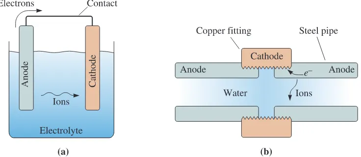
Components of an Electrochemical Cell
There are four
components of an electrochemical cell (Figure 23-3):
1. The
anode
gives up electrons to the circuit and corrodes.
2. The
cathode
receives electrons from the circuit by means of a chemical, or cathode,
reaction. Ions that combine with the electrons produce a byproduct at the cathode.
3. The anode and cathode must be electrically connected, usually by physical contact,
to permit the electrons to flow from the anode to the cathode and continue the
reaction.
4. A liquid
electrolyte
must be in contact with both the anode and the cathode. The
electrolyte is conductive, thus completing the circuit. It provides the means by
which metallic ions leave the anode surface and move to the cathode to accept the
electrons.
2 3 - 2
Electrochemical Corrosion
855
This description of an electrochemical cell defines electrochemical corrosion. If
metal ions are deposited onto the cathode,
electroplating
occurs.
Anode Reaction
The anode, which is a metal, undergoes an
oxidation
reac-tion
by which metal atoms are ionized. The metal ions enter the electrolytic solution, while
the electrons leave the anode through the electrical connection:
M
:
M
n++
ne
-(23-1)
Because metal ions leave the anode, the anode corrodes, or oxidizes.
Cathode Reaction in Electroplating
In electroplating, a
cathodic
reduction reaction,
which is the reverse of the anode reaction, occurs at the
cathode:
M
n++
ne
-:
M
(23-2)
The metal ions, either intentionally added to the electrolyte or formed by the anode
reac-tion, combine with electrons at the cathode. The metal then plates out and covers the
cath-ode surface.
Cathode Reactions in Corrosion
Except in unusual conditions,
plating of a metal does not occur during electrochemical corrosion. Instead, the reduction
reaction forms a gas, solid, or liquid byproduct at the cathode (Figure 23-4).
1.
The hydrogen electrode
: In oxygen-free liquids, such as hydrochloric acid (HCl) or
stagnant water, hydrogen gas may be evolved at the cathode:
2H
++
2
e
-:
H
2q
(gas)
(23-3)
If zinc were placed in such an environment, we would find that the overall reaction is
Zn
:
Zn
2++
2
e
-(anode reaction)
2H
++
2
e
-:
H
2
q
(cathode reaction)
(23-4)
Zn
+
2H
+:
Zn
2++
H
2
q
(overall reaction)
The zinc anode gradually dissolves, and hydrogen bubbles continue to evolve at the
cathode.
2.
The oxygen electrode
: In aerated water, oxygen is available to the cathode, and
hydroxyl, or (OH)
-, ions form:
(23-5)
The oxygen electrode enriches the electrolyte in (OH)
-ions. These ions react with
posi-tively charged metallic ions and produce a solid product. In the case of rusting of iron:
(23-6)
Fe
+
1
2
O
2+
H
2O
:
Fe(OH)
2(overall reaction)
Fe
2++
2(OH)
-:
Fe(OH)
2
(cathode reactions)
1
2
O
2+
H
2O
+
2
e
-:
2(OH)
-Fe
:
Fe
2++
2
e
-(anode reaction)
1
2
O
2+
H
2O
+
2
e
-:
2(OH)
The reaction continues as the Fe(OH)
2reacts with more oxygen and water:
(23-7)
Fe(OH)
3is commonly known as
rust.
3.
The water electrode
: In oxidizing acids, the cathode reaction produces water as a
byproduct:
O
2+
4H
++
4
e
-:
2H
2O
(23-8)
If a continuous supply of both oxygen and hydrogen is available, the water electrode
pro-duces neither a buildup of solid rust nor a high concentration or dilution of ions at the
cathode.
2Fe(OH)
2+
1
2
O
2+
H
2O
:
2Fe(OH)
3n
n
n
n
2 3 - 3 The Electrode Potential in Electrochemical Cells
857
23-3
The Electrode Potential in Electrochemical
Cells
In corrosion, a potential naturally develops when a material is placed in a solution. Let’s
see how the potential required to drive the corrosion reaction develops.
Electrode Potential
When a pure metal is placed in an electrolyte, an
electrode potential
develops that is related to the tendency of the material to give up its
electrons; however, the driving force for the oxidation reaction is offset by an equal but
opposite driving force for the reduction reaction. No net corrosion occurs. Consequently,
we cannot measure the electrode potential for a single electrode material.
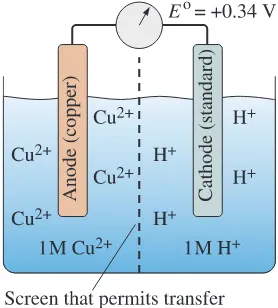
Electromotive Force Series
To determine the tendency of a metal
to give up its electrons, we measure the potential difference between the metal and a
standard electrode using a half-cell (Figure 23-5). The metal electrode to be tested is placed
in a 1 molar (M) solution of its ions. A reference electrode is also placed in a 1 M solution
of ions. The reference electrode is typically an inert metal that conducts electrons but
does not react with the electrolyte. The use of a 1 M solution of hydrogen (H
+) ions with
the reference electrode is common. The reaction that occurs at this hydrogen electrode is
2H
++
2
e
-=
H
2
. H
2gas is supplied to the hydrogen electrode. An electrochemical cell such
as this is known as a standard cell when the measurements are made at 25°C and
atmos-pheric pressure with 1 M electrolyte concentrations. The two electrolytes are in electrical
contact but are not permitted to mix with one another. Each electrode establishes its own
electrode potential. By measuring the voltage between the two electrodes when the circuit
is open, we obtain the potential difference. The potential of the hydrogen electrode is
arbi-trarily set equal to zero volts. If the metal has a greater tendency to give up electrons than
the hydrogen electrode, then the potential of the metal is negative—the metal is anodic
with respect to the hydrogen electrode. If the potential of the metal is positive, the metal
is cathodic with respect to the hydrogen electrode.
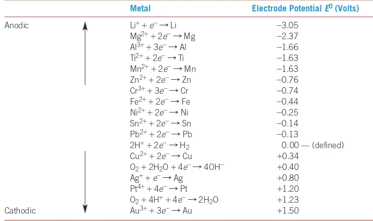
The
electromotive force
(or
emf
)
series
shown in Table 23-1 compares the standard
electrode potential
E
0for each metal with that of the hydrogen electrode under standard
Figure 23-5
The half-cell used to measure the electrode potential of copper under standard conditions. The electrode potential of copper is the potential difference between it and the standard hydrogen electrode in an open circuit. Since E0is greater than zero, copper is cathodic
conditions of 25°C and a 1 M solution of ions in the electrolyte. Note that the
measure-ment of the potential is made when the electric circuit is open. The voltage difference begins
to change as soon as the circuit is closed.
The more negative the value of potential for the oxidation of metal, the more
elec-tropositive is the metal; this means the metal will have a higher tendency to undergo an
oxi-dation reaction. For example, alkali and alkaline earth metals (e.g., Li, K, Ba, Sr, and Mg)
are so reactive that they have to be kept under conditions that prevent any contact with
oxy-gen. On the other hand, metals that are toward the bottom of the chart (e.g., Ag, Au, and
Pt) will not tend to react with oxygen. This is why we call them “noble metals.” Metals such
as Fe, Cu, and Ni have intermediate reactivities; however, this is not the only consideration.
Aluminum, for example, has a strongly negative standard electrode potential and does react
easily with oxygen to form aluminum oxide; it also reacts easily with fluoride to form
alu-minum fluoride. Both of these compounds form a tenacious and impervious layer that helps
stop further corrosion. Titanium also reacts readily with oxygen. The quickly formed
tita-nium oxide creates a barrier that prevents the further diffusion of species and, thus, avoids
further oxidation. This is why both aluminum and titanium are highly reactive, but can resist
corrosion exceptionally well. Note that the emf series tells us about the thermodynamic
fea-sibility and driving force, it does
not
tell us about the kinetics of the reaction.
Effect of Concentration on the Electrode Potential
The electrode potential depends on the concentration of the electrolyte. At 25°C, the
Nernst equation
gives the electrode potential in nonstandard solutions:
(23-9)
where
E
is the electrode potential in a solution containing a concentration
C
ionof the
metal in molar units,
n
is the charge on the metallic ion, and
E
0is the standard electrode
potential in a 1 M solution. Note that when
C
ion=
1,
E
=
E
0. The example that follows
illustrates the calculation of the electrode potential.
E
=
E
0+
0.0592
n
log (
Cion
)
TABLE 23-1■The standard reduction potentials for selected elements and reactions
Metal Electrode Potential E0(Volts)
Anodic Li++e-:Li -3.05
Mg2++2e-:Mg -2.37
Al3++3e-:Al -1.66
Ti2++2e-:Ti -1.63
Mn2++2e-:Mn -1.63
Zn2++2e-:Zn -0.76
Cr3++3e-:Cr -0.74
Fe2++2e-:Fe -0.44
Ni2++2e-:Ni -0.25
Sn2++2e-:Sn -0.14
Pb2++2e-:Pb -0.13
2H++2e-:H
2 0.00 — (defined)
Cu2++2e-:Cu +0.34
O2+2H2O +4e-:4OH- +0.40
Ag++e-:Ag +0.80
Pt4++4e-:Pt +1.20
O2+4H++4e-:2H2O +1.23
2 3 - 3 The Electrode Potential in Electrochemical Cells
859
Example 23-1
Half-Cell Potential for Copper
Suppose 1 g of copper as Cu
2+is dissolved in 1000 g of water to produce an
elec-trolyte. Calculate the electrode potential of the copper half-cell in this elecelec-trolyte.
Assume
T
=
25°C.
SOLUTION
From chemistry, we know that a standard 1 M solution of Cu
2+is obtained when we
add 1 mol of Cu
2+(an amount equal to the atomic mass of copper) to 1000 g of
water. The atomic mass of copper is 63.54 g
>
mol. The concentration of the
solu-tion when only 1 g of copper is added must be
From the Nernst equation, with
n
=
2 and
E
0= +
0.34 V,
Rate of Corrosion or Plating
The amount of metal plated on the
cathode in electroplating, or removed from the anode by corrosion, can be determined
from
Faraday’s equation
,
(23-10)
where
w
is the weight plated or corroded (g),
I
is the current (A),
M
is the atomic mass of
the metal,
n
is the charge on the metal ion,
t
is the time (s), and F is Faraday’s constant
(96,500 C). This law basically states that one gram equivalent of a metal will be deposited
by 96,500 C of charge. Often the current is expressed in terms of current density,
i
=
I>A
,
so Equation 23-10 becomes
(23-11)
where the area
A
(cm
2) is the surface area of the anode or cathode.
The following examples illustrate the use of Faraday’s equation to calculate the
current density.
w
=
iAtM
n
F
w
=
ItM
n
F
=
0.34
+
(0.0296)(
-
1.8)
=
0.29
V
E
=
E
0+
0.0592
n
log(
C
ion)
=
0.34
+
0.0592
2
log(0.0157)
Cion
=
1
63.54
=
0.0157
M
Example 23-2
Design of a Copper Plating Process
Design a process to electroplate a 0.1-cm-thick layer of copper onto a 1 cm
*
1 cm
cathode surface.
SOLUTION
In order for us to produce a 0.1-cm-thick layer on a 1 cm
2surface area, the mass of
copper must be
Volume of copper
=
(1 cm
)(0.1 cm)
=
0.1 cm
Mass of copper
=
(8.93 g
>
cm
3)(0.1 cm
3)
=
0.893 g
From Faraday’s equation, where
M
Cu=
63.54 g
>
mol and
n
=
2:
Therefore, we might use several different combinations of current and time to
pro-duce the copper plate:
Current Time
0.1 A 27,124 s =7.5 h 1.0 A 2,712 s =45.2 min 10.0 A 271.2 s =4.5 min 100.0 A 27.12 s =0.45 min
Our choice of the exact combination of current and time might be made on
the basis of the rate of production and quality of the plated copper. Low currents
require very long plating times, perhaps making the process economically
unsound. High currents, however, may reduce plating efficiencies. The plating
effectiveness may depend on the composition of the electrolyte containing the
cop-per ions, as well as on any impurities or additives that are present. Currents such
as 10 A or 100 A are too high—they can initiate other side reactions that are not
desired. The deposit may also not be uniform and smooth. Additional background
or experimentation may be needed to obtain the most economical and efficient
plating process. A current of
!
1 A and a time of
!
45 minutes are not uncommon
in electroplating operations.
It
=
wn
F
M
=
(0.893)(2)(96,500)
63.54
=
2712
A
#
s
Example 23-3
Corrosion of Iron
An iron container 10 cm
*
10 cm at its base is filled to a height of 20 cm with a
corrosive liquid. A current is produced as a result of an electrolytic cell, and after
four weeks, the container has decreased in weight by 70 g. Calculate (a) the current
and (b) the current density involved in the corrosion of the iron.
SOLUTION
(a) The total exposure time is
t
=
(4 wk)(7 d
>
wk)(24 h
>
d)(3600 s
>
h)
=
2.42
*
10
6s
From Faraday’s equation, using
n
=
2 and
M
=
55.847 g
>
mol,
=
0.1
A
I
=
wn
F
tM
=
2 3 - 4 The Corrosion Current and Polarization
861
(b) The total surface area of iron in contact with the corrosive liquid and the
current density are
i
=
I
A
=
0.1
900
=
1.11
*
10
-4
A
>
cm
2A
=
(4
sides)(10
*
20)
+
(1
bottom)(10
*
10)
=
900
cm
2Example 23-4
Copper-Zinc Corrosion Cell
Suppose that in a corrosion cell composed of copper and zinc, the current density
at the copper cathode is 0.05 A
>
cm
2. The area of both the copper and zinc
elec-trodes is 100 cm
2. Calculate (a) the corrosion current, (b) the current density at the
zinc anode, and (c) the zinc loss per hour.
SOLUTION
(a) The corrosion current is
I
=
i
CuA
Cu=
(0.05 A
>
cm
2)(100 cm
2)
=
5 A
(b) The current in the cell is the same everywhere. Thus,
(c) The atomic mass of zinc is 65.38 g
>
mol. From Faraday’s equation:
=
6.1
g
>
h
w
zinc loss=
ItM
n
F
=
a
5
A
cm
2b
(3600
s
>
h)(65.38
g
>
mol)
(2)(96,500
C)
i
Zn=
I
A
Zn=
5
100
=
0.05
A
>
cm
223-4
The Corrosion Current and Polarization
Activation Polarization
This kind of polarization is related to the
energy required to cause the anode or cathode reactions to occur. If we can increase the
degree of polarization, these reactions occur with greater difficulty, and the rate of
cor-rosion is reduced. Small differences in composition and structure in the anode and
cath-ode materials dramatically change the activation polarization. Segregation effects in the
electrodes cause the activation polarization to vary from one location to another. These
factors make it difficult to predict the corrosion current.
Concentration Polarization
After corrosion begins, the
concentra-tion of ions at the anode or cathode surface may change. For example, a higher
concen-tration of metal ions may exist at the anode if the ions are unable to diffuse rapidly into
the electrolyte. Hydrogen ions may be depleted at the cathode in a hydrogen electrode, or
a high (OH)
-concentration may develop at the cathode in an oxygen electrode. When this
situation occurs, either the anode or cathode reaction is stifled because fewer electrons
are released at the anode or accepted at the cathode.
In any of these examples, the current density, and thus the rate of corrosion,
decreases because of concentration polarization. Normally, the polarization is less
pro-nounced when the electrolyte is highly concentrated, the temperature is increased, or the
electrolyte is vigorously agitated. Each of these factors increases the current density and
encourages electrochemical corrosion.
Resistance Polarization
This type of polarization is caused by
the electrical resistivity of the electrolyte. If a greater resistance to the flow of the
cur-rent is offered, the rate of corrosion is reduced. Again, the degree of resistance
polar-ization may change as the composition of the electrolyte changes during the corrosion
process.
23-5
Types of Electrochemical Corrosion
In this section, we will look at some of the more common forms taken by
electrochemi-cal corrosion. First, there is
uniform attack.
When a metal is placed in an electrolyte, some
regions are anodic to other regions; however, the location of these regions moves and even
reverses from time to time. Since the anode and cathode regions continually shift, the
metal corrodes uniformly.
Galvanic attack
occurs when certain areas always act as anodes, whereas other
areas always act as cathodes. These electrochemical cells are called galvanic cells and can
be separated into three types:
composition cells, stress cells,
and
concentration cells
.
2 3 - 5
Types of Electrochemical Corrosion
863
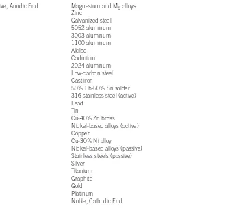
TABLE 23-2■The galvanic series in seawater
Active, Anodic End Magnesium and Mg alloys Zinc
Galvanized steel 5052 aluminum 3003 aluminum 1100 aluminum Alclad
Cadmium 2024 aluminum Low-carbon steel Cast iron
50% Pb-50% Sn solder 316 stainless steel (active) Lead
Tin
Cu-40% Zn brass
Nickel-based alloys (active) Copper
Cu-30% Ni alloy
Nickel-based alloys (passive) Stainless steels (passive) Silver
Titanium Graphite Gold Platinum
Noble, Cathodic End
(After ASM Metals Handbook, Vol. 10, 8th Ed., Copyright 1975 ASM International.)
Example 23-5
Corrosion of a Soldered Brass Fitting
A brass fitting used in a marine application is joined by soldering with lead-tin
sol-der. Will the brass or the solder corrode?
SOLUTION
From the galvanic series, we find that all of the copper-based alloys are more
cathodic than a 50% Pb-50% Sn solder. Thus, the solder is the anode and corrodes.
In a similar manner, the corrosion of solder can contaminate water in freshwater
plumbing systems with lead.
Composition cells also develop in two-phase alloys, where one phase is more
anodic than the other. Since ferrite is anodic to cementite in steel, small microcells cause
steel to galvanically corrode (Figure 23-6). Almost always, a two-phase alloy has less
resist-ance to corrosion than a single-phase alloy of a similar composition.
Intergranular corrosion
occurs when the precipitation of a second phase or
seg-regation at grain boundaries produces a galvanic cell. In zinc alloys, for example,
impuri-ties such as cadmium, tin, and lead segregate at the grain boundaries during solidification.
The grain boundaries are anodic compared to the remainder of the grains, and corrosion
of the grain boundary metal occurs (Figure 23-7). In austenitic stainless steels, chromium
carbides can precipitate at grain boundaries [Figure 23-6(b)]. The formation of the
car-bides removes chromium from the austenite adjacent to the boundaries. The
low-chromium (
"
12% Cr) austenite at the grain boundaries is anodic to the remainder of the
grain and corrosion occurs at the grain boundaries. In certain cold-worked aluminum
alloys, grain boundaries corrode rapidly due to the presence of detrimental precipitates.
This causes the grains of aluminum to peel back like the pages of a book or leaves. This
is known as exfoliation.
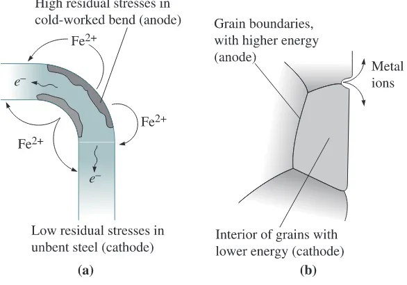
Stress Cells
Stress cells develop when a metal contains regions with
differ-ent local stresses. The most highly stressed or high-energy regions act as anodes to the
less-stressed cathodic areas (Figure 23-8). Regions with a finer grain size, or a higher
Figure 23-7
Micrograph of intergranular corrosion in a zinc die casting. Segregation of impurities to the grain boundaries produces
microgalvanic corrosion cells (* 50). (Reprinted courtesy of Don Askeland.)
2 3 - 5
Types of Electrochemical Corrosion
865
density of grain boundaries, are anodic to coarse-grained regions of the same material.
Highly cold-worked areas are anodic to less cold-worked areas.
Stress corrosion
occurs by galvanic action, but other mechanisms, such as the
adsorption of impurities at the tip of an existing crack, may also occur. Failure occurs as
a result of corrosion and an applied stress. Higher applied stresses reduce the time required
for failure.
Fatigue failures are also initiated or accelerated when corrosion occurs.
Corrosion
fatigue
can reduce fatigue properties by initiating cracks (perhaps by producing pits or
crevices) and by increasing the rate at which the cracks propagate.
Figure 23-8 Examples of stress cells. (a) Cold work required to bend a steel bar introduces high residual stresses at the bend, which then is anodic and corrodes. (b) Because grain boundaries have high energy, they are anodic and corrode.
Example 23-6
Corrosion of Cold-Drawn Steel
A cold-drawn steel wire is formed into a nail by additional deformation, producing
the point at one end and the head at the other. Where will the most severe corrosion
of the nail occur?
SOLUTION
Since the head and point have been cold-worked an additional amount compared
with the shank of the nail, the head and point serve as anodes and corrode most
rapidly.
contact with the most concentrated solution is the cathode; the metal in contact with the
dilute solution is the anode.
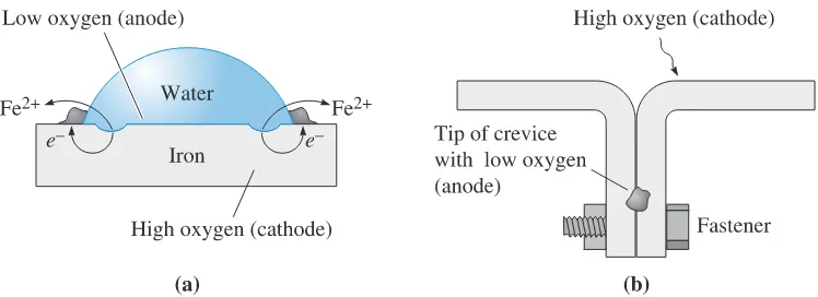
The oxygen concentration cell (often referred to as
oxygen starvation
) occurs when
the cathode reaction is the oxygen electrode, H
2O
+
O
2+
2
e
-:
2(OH)
-. Electrons flow
from the low oxygen region, which serves as the anode, to the high oxygen region, which
serves as the cathode.
Deposits, such as rust or water droplets, shield the underlying metal from oxygen.
Consequently, the metal under the deposit is the anode and corrodes. This causes one
form of pitting corrosion. Waterline corrosion is similar. Metal above the waterline is
exposed to oxygen, while metal beneath the waterline is deprived of oxygen; hence, the
metal underwater corrodes. Normally, the metal far below the surface corrodes more
slowly than metal just below the waterline due to differences in the distance that electrons
must travel. Because cracks and crevices have a lower oxygen concentration than the
sur-rounding base metal, the tip of a crack or crevice is the anode, causing
crevice corrosion.
Pipe buried in soil may corrode because of differences in the composition of the
soil. Velocity differences may cause concentration differences. Stagnant water contains
low oxygen concentrations, whereas fast-moving, aerated water contains higher oxygen
concentrations. Metal near stagnant water is anodic and corrodes. The following is an
example of corrosion due to water.
1 2
Figure 23-9 Concentration cells: (a) Corrosion occurs beneath a water droplet on a steel plate due to low oxygen concentration in the water. (b) Corrosion occurs at the tip of a crevice because of limited access to oxygen.
Example 23-7
Corrosion of Crimped Steel
Two pieces of steel are joined mechanically by crimping the edges. Why would this
be a bad idea if the steel is then exposed to water? If the water contains salt, would
corrosion be affected?
SOLUTION
By crimping the steel edges, we produce a crevice. The region in the crevice is exposed
to less air and moisture, so it behaves as the anode in a concentration cell. The steel
in the crevice corrodes.
2 3 - 5
Types of Electrochemical Corrosion
867
Microbial Corrosion
Various microbes, such as fungi and bacteria,
cre-ate conditions that encourage electrochemical corrosion. Particularly in aqueous
environ-ments, these organisms grow on metallic surfaces. The organisms typically form colonies
that are not continuous. The presence of the colonies and the byproducts of the growth
of the organisms produce changes in the environment and, hence, the rate at which
cor-rosion occurs.
Some bacteria reduce sulfates in the environment, producing sulfuric acid, which
in turn attacks metal. The bacteria may be either aerobic (which thrive when oxygen is
available) or anaerobic (which do not need oxygen to grow). Such bacteria cause attacks
on a variety of metals, including steels, stainless steels, aluminum, and copper, as well as
some ceramics and concrete. A common example occurs in aluminum fuel tanks for
air-craft. When the fuel, typically kerosene, is contaminated with moisture, bacteria grow and
excrete acids. The acids attack the aluminum, eventually causing the fuel tank to leak.
The growth of colonies of organisms on a metal surface leads to the
develop-ment of oxygen concentration cells (Figure 23-10). Areas beneath the colonies are anodic,
whereas unaffected areas are cathodic. In addition, the colonies of organisms reduce the
rate of diffusion of oxygen to the metal, and—even if the oxygen does diffuse into the
colony—the organisms tend to consume the oxygen. The concentration cell produces
pit-ting beneath the regions covered with the organisms. Growth of the organisms, which may
include products of the corrosion of the metal, produces accumulations (called
tubercules
)
that may plug pipes or clog water-cooling systems in nuclear reactors, submarines, or
chemical reactors.
Figure 23-10
23-6
Protection Against Electrochemical
Corrosion
A number of techniques are used to combat corrosion, including proper design and
mate-rials selection and the use of coatings, inhibitors, cathodic protection, and passivation.
Design
Proper design of metal structures can slow or even avoid corrosion. Some
of the steps that should be taken to combat corrosion are as follows:
1. Prevent the formation of galvanic cells. This can be achieved by using similar
met-als or alloys. For example, steel pipe is frequently connected to brass plumbing
fixtures, producing a galvanic cell that causes the steel to corrode. By using
inter-mediate plastic fittings to electrically insulate the steel and brass, this problem can
be minimized.
2. Make the anode area much larger than the cathode area. For example, copper
ets can be used to fasten steel sheet. Because of the small area of the copper
riv-ets, a limited cathode reaction occurs. The copper accepts few electrons, and the
steel anode reaction proceeds slowly. If, on the other hand, steel rivets are used for
joining copper sheet, the small steel anode area gives up many electrons, which are
accepted by the large copper cathode area; corrosion of the steel rivets is then very
rapid. This is illustrated in the following example.
Example 23-8
Effect of Areas on Corrosion Rate for Copper-Zinc Couple
Consider a copper-zinc corrosion couple. If the current density at the copper
cath-ode is 0.05 A
>
cm
2, calculate the weight loss of zinc per hour if (1) the copper
cath-ode area is 100 cm
2and the zinc anode area is 1 cm
2and (2) the copper cathode area
is 1 cm
2and the zinc anode area is 100 cm
2.
SOLUTION
For the small zinc anode area,
For the large zinc anode area,
The rate of corrosion of the zinc is reduced significantly when the zinc anode is much
larger than the cathode.
wZn
=
ItM
n
F
=
(0.05
A
>
cm
2)(3600
s)
Q
65.38
g
mol
R
(2)(96,500
C)
=
0.061g
>
h
I
=
i
CuA
Cu=
(0.05
A
>
cm
2)(1
cm
2)
=
0.05
A
w
Zn=
ItM
n
F
=
(5)(3600)(65.38)
2 3 - 6 Protection Against Electrochemical Corrosion
869
Figure 23-11 Alternative methods for joining two pieces of steel: (a) Fasteners may produce a concentration cell, (b) brazing or soldering may produce a composition cell, and (c) welding with a filler metal that matches the base metal may avoid the formation of galvanic cells.
3. Design components so that fluid systems are closed, rather than open, and so that
stagnant pools of liquid do not collect. Partly filled tanks undergo waterline
corrosion. Open systems continuously dissolve gas, providing ions that participate
in the cathode reaction, and encourage concentration cells.
4. Avoid crevices between assembled or joined materials (Figure 23-11). Welding may
be a better joining technique than brazing, soldering, or mechanical fastening.
Galvanic cells develop in brazing or soldering since the filler metals have a
differ-ent composition from the metal being joined. Mechanical fasteners produce
crevices that lead to concentration cells. If the filler metal is closely matched to
the base metal, welding may prevent these cells from developing.
5. In some cases, the rate of corrosion cannot be reduced to a level that will not
inter-fere with the expected lifetime of the component. In such cases, the assembly
should be designed in such a manner that the corroded part can be easily and
eco-nomically replaced.
Coatings
Coatings are used to isolate the anode and cathode regions. Coatings
also prevent diffusion of oxygen or water vapor that initiates corrosion or oxidation.
Temporary coatings, such as grease or oil, provide some protection but are easily
dis-rupted. Organic coatings, such as paint, or ceramic coatings, such as enamel or glass,
pro-vide better protection; however, if the coating is disrupted, a small anodic site is exposed
that undergoes rapid, localized corrosion.
Metallic coatings include tin-plated and hot-dip galvanized (zinc-plated) steel
(Figure 23-12). This was discussed in earlier chapters on ferrous materials. A continuous
coating of either metal isolates the steel from the electrolyte; however, when the coating
is scratched, exposing the underlying steel, the zinc continues to be effective, because zinc
is anodic to steel. Since the area of the exposed steel cathode is small, the zinc coating
corrodes at a very slow rate and the steel remains protected. In contrast, steel is anodic to
tin, so a small steel anode is created when the tin is scratched, and rapid corrosion of the
steel subsequently occurs.
oxide layers form on the surface of aluminum, chromium, and stainless steel. These
oxides exclude the electrolyte and prevent the formation of galvanic cells. Components
such as reaction vessels can also be lined with corrosion-resistant Teflon
TMor other
plastics.
Inhibitors
When added to the electrolyte, some chemicals migrate preferentially
to the anode or cathode surface and produce concentration or resistance polarization—
that is, they are
inhibitors
. Chromate salts perform this function in automobile radiators.
A variety of chromates, phosphates, molybdates, and nitrites produce protective films on
anodes or cathodes in power plants and heat exchangers, thus stifling the electrochemical
cell. Although the exact contents and the mechanism by which it functions are not
clear, the popular lubricant WD-40
TMworks from the action of inhibitors. The name
“WD-40
TM” was designated water displacement (WD) that worked on the fortieth
exper-imental attempt!
Cathodic Protection
We can protect against corrosion by supplying the
metal with electrons and forcing the metal to be a cathode (Figure 23-13). Cathodic
pro-tection can use a sacrificial anode or an impressed voltage.
A
sacrificial anode
is attached to the material to be protected, forming an
electro-chemical circuit. The sacrificial anode corrodes, supplies electrons to the metal, and thereby
prevents an anode reaction at the metal. The sacrificial anode, typically zinc or
magne-sium, is consumed and must eventually be replaced. Applications include preventing the
Figure 23-12 Zinc-plated steel and tin-plated steel are protected differently. Zinc protects steel even when the coating is scratched since zinc is anodic to steel. Tin does not protect steel when the coating is disrupted since steel is anodic with respect to tin.2 3 - 6 Protection Against Electrochemical Corrosion
871
corrosion of buried pipelines, ships, off-shore drilling platforms, and water heaters. A
mag-nesium rod is used in many water heaters. The Mg serves as an anode and undergoes
dis-solution, thus protecting the steel from corroding.
An
impressed voltage
is obtained from a direct current source connected between
an auxiliary anode and the metal to be protected. Essentially, we have connected a battery
so that electrons flow to the metal, causing the metal to be the cathode. The auxiliary
anode, such as scrap iron, corrodes.
Passivation or Anodic Protection
Metals near the anodic end
of the galvanic series are active and serve as anodes in most electrolytic cells; however, if
these metals are made passive or more cathodic, they corrode at slower rates than normal.
Passivation
is accomplished by producing strong anodic polarization, preventing the
nor-mal anode reaction; thus the term anodic protection.
We cause passivation by exposing the metal to highly concentrated oxidizing
solu-tions. If iron is dipped in very concentrated nitric acid, the iron rapidly and uniformly
corrodes to form a thin, protective iron hydroxide coating. The coating protects the iron
from subsequent corrosion in nitric acid.
We can also cause passivation by increasing the potential on the anode above
a critical level. A passive film forms on the metal surface, causing strong anodic
polar-ization, and the current decreases to a very low level. Passivation of aluminum is called
anodizing
, and a thick oxide coating is produced. This oxide layer can be dyed to
pro-duce attractive colors. The Ta
2O
5oxide layer formed on tantalum wires is used to make
capacitors.
Materials Selection and Treatment
Corrosion can be
pre-vented or minimized by selecting appropriate materials and heat treatments. In castings,
for example, segregation causes tiny, localized galvanic cells that accelerate corrosion. We
can improve corrosion resistance with a homogenization heat treatment. When metals are
formed into finished shapes by bending, differences in the amount of cold work and
resid-ual stresses cause local stress cells. These may be minimized by a stress-relief anneal or a
full recrystallization anneal.
The heat treatment is particularly important in austenitic stainless steels
(Figure 23-14). When the steel cools slowly from 870 to 425°C, chromium carbides
pre-cipitate at the grain boundaries. Consequently the austenite at the grain boundaries
may contain less than 12% chromium, which is the minimum required to produce a
passive oxide layer. The steel is
sensitized
. Because the grain boundary regions are small
and highly anodic, rapid corrosion of the austenite at the grain boundaries occurs. We
can minimize the problem by several techniques.
1. If the steel contains less than 0.03% C, chromium carbides do not form.
2. If the percent chromium is very high, the austenite may not be depleted to below
12% Cr, even if chromium carbides form.
3. Addition of titanium or niobium ties up the carbon as TiC or NbC, preventing the
formation of chromium carbide. The steel is said to be
stabilized
.
4. The sensitization temperature range—425 to 870°C—should be avoided during
manufacture and service.
The following examples illustrate the design of a corrosion protection system.
Figure 23-14 (a) Austenitic stainless steels become sensitized when cooled slowly in the temperature range between 870 and 425°C. (b) Slow cooling permits chromium carbides to precipitate at grain boundaries. The local chromium content is depleted. (c) A quench anneal to dissolve the carbides may prevent intergranular corrosion.Example 23-9
Design of a Corrosion Protection System
Steel troughs are located in a field to provide drinking water for a herd of cattle.
The troughs frequently rust through and must be replaced. Design a system to
pre-vent or delay this problem.
SOLUTION
The troughs are likely a low-carbon, unalloyed steel containing ferrite and
cemen-tite, producing a composition cell. The waterline in the trough, which is partially
filled with water, provides a concentration cell. The trough is also exposed to the
environment, and the water is contaminated with impurities. Consequently,
corro-sion of the unprotected steel tank is to be expected.
2 3 - 6 Protection Against Electrochemical Corrosion
873
provide better corrosion resistance than the plain carbon steel, but both are
consid-erably more expensive than the current material.
We might suggest using cathodic protection; a small magnesium anode could be
attached to the inside of the trough. The anode corrodes sacrificially and prevents
corrosion of the steel. This would require that the farm operator regularly check the
tank to be sure that the anode is not completely consumed. We also want to be sure
that magnesium ions introduced into the water are not a health hazard.
Another approach would be to protect the steel trough using a suitable coating.
Painting the steel (that is, introducing a protective polymer coating) or using a
tin-plated steel provides protection as long as the coating is not disrupted.
The most likely approach is to use a galvanized steel, taking advantage of the
protective coating and the sacrificial behavior of the zinc. Corrosion is very slow
due to the large anode area, even if the coating is disrupted. Furthermore, the
gal-vanized steel is relatively inexpensive, readily available, and does not require frequent
inspection.
Example 23-10
Design of a Stainless Steel Weldment
A piping system used to transport a corrosive liquid is fabricated from 304 stainless
steel. Welding of the pipes is required to assemble the system. Unfortunately,
cor-rosion occurs, and the corrosive liquid leaks from the pipes near the weld. Identify
the problem and design a system to prevent corrosion in the future.
SOLUTION
Table 13-4 shows that 304 stainless steel contains 0.08% C, causing the steel to be
sensitized if it is improperly heated or cooled during welding. Figure 23-15 shows
the maximum temperatures reached in the fusion and heat-affected zones during
welding. A portion of the pipe in the HAZ heats into the sensitization temperature
Figure 23-15
The peak temperature surrounding a stainless steel weld and the
sensitized structure produced when the weld slowly cools (for
range, permitting chromium carbides to precipitate. If the cooling rate of the weld
is very slow, the fusion zone and other areas of the heat-affected zone may also be
affected. Sensitization of the weld area, therefore, is the likely reason for corrosion
of the pipe.
Several solutions to the problem may be considered. We might use a welding
process that provides very rapid rates of heat input, causing the weld to heat and cool
very quickly. If the steel is exposed to the sensitization temperature range for only a
brief time, chromium carbides may not precipitate. Joining processes such as laser
welding or electron-beam welding are high-rate-of-heat-input processes, but they
are expensive. In addition, electron beam welding requires the use of a vacuum, and
it may not be feasible to assemble the piping system in a vacuum chamber.
We might heat treat the assembly after the weld is made. By performing a
quench anneal, any precipitated carbides are re-dissolved during the anneal and do
not reform during quenching; however, it may be impossible to perform this
treat-ment on a large assembly.
We might check the original welding procedure to determine if the pipe was
preheated before joining in order to minimize the development of stresses due to
the welding process. If the pipe were preheated, sensitization would be more likely
to occur. We would recommend that any preheat procedure be suspended.
Perhaps our best design is to use a stainless steel that is not subject to
sensitiza-tion. For example, carbides do not precipitate in a 304L stainless steel, which
con-tains less than 0.03% C. The low-carbon stainless steels are more expensive than the
normal 304 steel; however, the extra cost does prevent corrosion and still permits us
to use conventional joining techniques.
23-7
Microbial Degradation and Biodegradable
Polymers
Attack by a variety of insects and microbes is one form of “corrosion” of polymers. Relatively
simple polymers (such as polyethylene, polypropylene, and polystyrene),
high-molecular-weight polymers, crystalline polymers, and thermosets are relatively immune to attack.
Some polymers—including polyesters, polyurethanes, cellulosics, and plasticized
polyvinyl chloride (which contains additives that reduce the degree of polymerization)—
are particularly vulnerable to microbial degradation. These polymers can be broken into
low-molecular-weight molecules by radiation or chemical attack until they are small
enough to be ingested by the microbes.
2 3 - 8
Oxidation and Other Gas Reactions
875
23-8
Oxidation and Other Gas Reactions
Materials of all types may react with oxygen and other gases. These reactions can, like
cor-rosion, alter the composition, properties, or integrity of a material. As mentioned before,
metals such as Al and Ti react with oxygen very readily.
Oxidation of Metals
Metals may react with oxygen to produce an oxide at
the surface. We are interested in three aspects of this reaction: the ease with which the metal
oxidizes, the nature of the oxide film that forms, and the rate at which
oxidation
occurs.
The ease with which oxidation occurs is given by the standard free energy of
for-mation for the oxide. The standard free energy of forfor-mation for an oxide can be
deter-mined from an Ellingham diagram, such as the one shown in Figure 23-16. Figure 23-16
shows that there is a large driving force for the oxidation of magnesium and aluminum
compared to the oxidation of nickel or copper. This is illustrated in the following example.
Standard free ener
gy of formation (G
°
)
(kcal/mol O
2
)
Figure 23-16 The standard free energy of formation of selected oxides as a function of temperature. A large negative free energy indicates a more stable oxide.
Example 23-11
Chromium-Based Steel Alloys
Explain why we should not add alloying elements such as chromium to pig iron
before the pig iron is converted to steel in a basic oxygen furnace at 1700°C.
SOLUTION
were already present before the steel making began, chromium would oxidize before
the carbon (Figure 23-16), since chromium oxide has a lower free energy of
forma-tion (or is more stable) than carbon dioxide (CO
2). Thus, any expensive chromium
added would be lost before the carbon was removed from the pig iron.
The type of oxide film influences the rate at which oxidation occurs (Figure 23-17).
For the
oxidation reaction
n
M
+
m
O
2:
M
nO
2m(23-12)
the
Pilling-Bedworth
(P-B)
ratio
is
(23-13)
where
M
is the atomic or molecular mass,
!
is the density, and
n
is the number of metal
atoms in the oxide, as defined in Equation 23-12.
If the Pilling-Bedworth ratio is less than one, the oxide occupies a smaller volume
than the metal from which it formed; the coating is therefore porous and oxidation
con-tinues rapidly—typical of metals such as magnesium. If the ratio is one to two, the
vol-umes of the oxide and metal are similar and an adherent, non-porous, protective film
P-B ratio
=
oxide volume per metal atom
metal volume per metal atom
=
(
M
oxide)(
r
metal)
n
(
Mmetal
)(
r
oxide)
Figure 23-17
2 3 - 8
Oxidation and Other Gas Reactions
877
forms—typical of aluminum and titanium. If the ratio exceeds two, the oxide occupies a
large volume and may flake from the surface, exposing fresh metal that continues to
oxi-dize—typical of iron. Although the Pilling-Bedworth equation historically has been used
to characterize oxide behavior, many exceptions to this behavior are observed. The use of
the P-B ratio equation is illustrated in the following example.
Example 23-12
Pilling-Bedworth Ratio
The density of aluminum is 2.7 g
>
cm
3and that of Al
2
O
3is about 4 g
>
cm
3. Describe the
characteristics of the aluminum-oxide film. Compare these with the oxide film that forms
on tungsten. The density of tungsten is 19.254 g
>
cm
3and that of WO
3
is 7.3 g
>
cm
3.
SOLUTION
For 2Al
+
3
>
2O
2:
Al
2O
3, the molecular weight of Al
2O
3is 101.96 g
>
mol and that
of aluminum is 26.981 g
>
mol.
For tungsten, W
+
3
>
2O
2:
WO
3. The molecular weight of WO
3is 231.85 g
>
mol and
that of tungsten is 183.85 g
>
mol.
Since P-B
M
1 for aluminum, the Al
2O
3film is nonporous and adherent, providing
protection to the underlying aluminum. Since P-B
#
2 for tungsten, the WO
3should
be nonadherent and nonprotective.
P-B
=
M
WO3r
WnM
Wr
WO3=
a
231.85
g
mol
b
(19.254
g
>
cm
3)
(1)
a
183.85
g
mol
b
(7.3
g
>
cm
3)
=
3.33
P-B
=
MAl
2O3r
AlnMAl
r
A12O3=
a
101.96
g
mol
b1
2.7
g
>
cm
32
(2)
a
26.981
g
mol
b
(4
g
>
cm
3)
=
1.28
The rate at which oxidation occurs depends on the access of oxygen to the metal
atoms. A linear rate of oxidation occurs when the oxide is porous (as in magnesium) and
oxygen has continued access to the metal surface:
y
=
k
t
(23-14)
where
y
is the thickness of the oxide,
t
is the time, and k is a constant that depends on the
metal and temperature.
A parabolic relationship is observed when diffusion of ions or electrons through
a nonporous oxide layer is the controlling factor. This relationship is observed in iron,
copper, and nickel:
Finally, a logarithmic relationship is observed for the growth of thin-oxide films that are
particularly protective, as for aluminum and possibly chromium:
y
=
k ln(c
t
+
1)
(23-16)
where k and c are constants for a particular temperature, environment, and composition.
The example that follows shows the calculation for the time required for a nickel sheet to
oxidize completely.
Example 23-13
Parabolic Oxidation Curve for Nickel
At 1000°C, pure nickel follows a parabolic oxidation curve given by the constant
k
=
3.9
*
10
-12cm
2>
s in an oxygen atmosphere. If this relationship is not affected by
the thickness of the oxide film, calculate the time required for a 0.1-cm nickel sheet
to oxidize completely.
SOLUTION
Assuming that the sheet oxidizes from both sides:
Temperature also affects the rate of oxidation. In many metals, the rate of
oxida-tion is controlled by the rate of diffusion of oxygen or metal ions through the oxide. If
oxy-gen diffusion is more rapid, oxidation occurs between the oxide and the metal; if the metal
ion diffusion is more rapid, oxidation occurs at the oxide-atmosphere interface.
Consequently, we expect oxidation rates to follow an Arrhenius relationship, increasing
exponentially as the temperature increases.
t
=
(0.05
cm)
2
3.9
*
10
-12cm
2>
s
=
6.4
*
10
8s
=
20.3
years
y
=
1
k
t
=
C
a
3.9
*
10
-12cm
2
s
b
(
t
)
=
0.1
cm
2
sides
=
0.05
cm
2 3 - 9 Wear and Erosion
879
Polymers also degrade by the loss of side groups on the chain. Chloride ions [in
polyvinyl chloride (PVC)] and benzene rings (in polystyrene) are lost from the chain,
form-ing byproducts. For example, as polyvinyl chloride is degraded, hydrochloric acid (HCl)
is produced. Hydrogen atoms are bonded more strongly to the chains; thus, polyethylene
does not degrade as easily as PVC or polystyrene. Fluoride ions (in Teflon
TM) are more
difficult to remove than hydrogen atoms, providing Teflon
TMwith its high temperature
resistance. As mentioned before, degradation of polymers, such as PCL, PLGA, and PLA,
actually can be useful for certain biomedical applications (e.g., sutures that dissolve) and
also in the development of environmentally friendly products.
23-9
Wear and Erosion
Wear and erosion remove material from a component by mechanical attack of solids or
liquids. Corrosion and mechanical failure also contribute to this type of attack.
Adhesive Wear
Adhesive wear
—also known as scoring, galling, or seizing—
occurs when two solid surfaces slide over one another under pressure. Surface projections,
or asperities, are plastically deformed and eventually welded together by the high local
pressures (Figure 23-18). As sliding continues, these bonds are broken, producing cavities
on one surface, projections on the second surface, and frequently tiny, abrasive particles—
all of which contribute to further wear of the surfaces.
Many factors may be considered in trying to improve the wear resistance of
mate-rials. Designing components so that loads are small, surfaces are smooth, and continual
lubrication is possible helps prevent adhesions that cause the loss of material.
The properties and microstructure of the material are also important. Normally,
if both surfaces have high hardnesses, the wear rate is low. High strength, to help resist the
applied loads, and good toughness and ductility, which prevent the tearing of material
from the surface, may be beneficial. Ceramic materials, with their exceptional hardness, are
expected to provide good adhesive wear resistance.
Figure 23-18
Wear resistance of polymers can be improved if the coefficient of friction
is reduced by the addition of polytetrafluoroethylene (Teflon
TM) or if the polymer
is strengthened by the introduction of reinforcing fibers such as glass, carbon, or
aramid.
Abrasive Wear
When material is removed from a surface by contact with
hard particles,
abrasive wear
occurs. The particles either may be present at the surface
of a second material or may exist as loose particles between two surfaces (Figure 23-19).
This type of wear is common in machinery such as plows, scraper blades, crushers, and
grinders used to handle abrasive materials and may also occur when hard particles are
unintentionally introduced into moving parts of machinery. Abrasive wear is also used
for grinding operations to remove material intentionally. In many automotive
applica-tions (e.g., dampers, gears, pistons, and cylinders), abrasive wear behavior is a major
concern.
Materials with a high hardness, good toughness, and high hot strength are most
resistant to abrasive wear. Typical materials used for abrasive-wear applications include
quenched and tempered steels; carburized or surface-hardened steels; cobalt alloys such
as Stellite; composite materials, including tungsten carbide cermets; white cast irons; and
hard surfaces produced by welding. Most ceramic materials also resist wear effectively
because of their high hardness; however, their brittleness may sometimes limit their
use-fulness in abrasive wear conditions.
Liquid Erosion
The integrity of a material may be destroyed by erosion
caused by high pressures associated with a moving liquid. The liquid causes strain
hard-ening of the metal surface, leading to localized deformation, cracking, and loss of
mate-rial. Two types of liquid erosion deserve mention.
Cavitation
occurs when a liquid containing a dissolved gas enters a low pressure
region. Gas bubbles, which precipitate and grow in the liquid in the low pressure
environ-ment, collapse when the pressure subsequently increases. The high-pressure, local shock
wave that is produced by the collapse may exert a pressure of thousands of atmospheres
against the surrounding material. Cavitation is frequently encountered in propellers, dams
and spillways, and hydraulic pumps.
Summary
881
the rapid lateral movement of the droplets from the impact point along the metal surface.
Water droplets carried by steam may erode turbine blades in steam generators and nuclear
power plants.
Liquid erosion can be minimized by proper materials selection and design.
Minimizing the liquid velocity, ensuring that the liquid is deaerated, selection of hard,
tough materials to absorb the impact of the droplets, and coating the material with an
energy-absorbing elastomer all may help minimize erosion.
Summary
•
About 6% of the gross domestic product in the United States is used to combat
corro-sion. Corrosion causes deterioration of all types of materials. Designers and engineers
must know how corrosion occurs in order to consider suitable designs, materials
selec-tion, or protective measures.
•
In chemical corrosion, a material is dissolved in a solvent, resulting in the loss of
material. All materials—metals, ceramics, polymers, and composites—are subject to
this form of attack. The choice of appropriate materials having a low solubility in a
given solvent or use of inert coatings on materials helps avoid or reduce chemical
corrosion.
•
Electrochemical corrosion requires that a complete electric circuit develop. The anode
corrodes and a byproduct such as rust forms at the cathode. Because an electric circuit
is required, this form of corrosion is most serious in metals and alloys.
•
Composition cells are formed by the presence of two different metals, two different
phases within a single alloy, or even segregation within a single phase.
•
Stress cells form when the level of residual or applied stresses varies within the metal;
the regions subjected to the highest stress are anodic and, consequently, they corrode.
Stress corrosion cracking and corrosion fatigue are examples of stress cells.
•
Concentration cells form when a metal is exposed to a nonuniform electrolyte; for
example, the portion of a metal exposed to the lowest oxygen content corrodes. Pitting
corrosion, waterline corrosion, and crevice corrosion are examples of these cells.
Microbial corrosion, in which colonies of organisms such as bacteria grow on the metal
surface, is another example of a concentration cell.
•
Electrochemical corrosion can be minimized or prevented by using electrical
insula-tors to break the electric circuit, designing and manufacturing assemblies without
crevices, designing assemblies so that the anode area is large compared to that of the
cathode, using protective and even sacrificial coatings, inhibiting the action of the
electrolyte, supplying electrons to the metal by means of an impressed voltage, using
heat treatments that reduce residual stresses or segregation, and a host of other
actions.
oxygen and metallic atoms is often important; therefore oxidation occurs most rapidly
at elevated temperatures.
•
Other factors, such as attack by microbes, damage caused by radiation, and wear or
ero-sion of a material, may also cause a material to deteriorate.
Glossary
Abrasive wearRemoval of material from surfaces by the cutting action of particles.
Adhesive wearRemoval of material from moving surfaces by momentary local bonding and then
bond fracture at the surfaces.
AnodeThe location at which corrosion occurs as electrons and ions are given up in an electrochem-ical cell.
AnodizingAn anodic protection technique in which a thick oxide layer is deliberately produced on a metal surface.
CathodeThe location at which electrons are accepted and a byproduct is produced during electro-chemical corrosion.
CavitationErosion of a material surface by the pressures produced when a gas bubble collapses within a moving liquid.
Chemical corrosionRemoval of atoms from a material by