Have You Ever Wondered?
• Whether water really does “freeze” at 0°C and “boil” at 100°C?
• What is the process used to produce several million pounds of steels and other alloys?
• Is there a specific melting temperature for an alloy or a thermoplastic material?
• What factors determine the strength of a cast product?
• Why are most glasses and glass-ceramics processed by melting and casting?
Principles of Solidification
O
f all the processing techniques used in the manufacturing of materials, solid-ification is probably the most important. All metallic materials, as well as many ceramics, inorganic glasses, and thermoplastic polymers, are liquid or molten at some point during processing. Like water freezes to ice, molten materials solidify as they cool below their freezing temperature. In Chapter 3, we learned how materi-als are classified based on their atomic, ionic, or molecular order. During the solidifi-cation of materials that crystallize, the atomic arrangement changes from a short-range order (SRO) to a long-range order (LRO). The solidification of crystalline materials requires two steps. In the first step, ultra-fine crystallites, known as the nuclei of a solid phase, form from the liquid. In the second step, which can overlap with the first, the ultra-fine solid crystallites begin to grow as atoms from the liquid are attached to the nuclei until no liquid remains. Some materials, such as inorganic silicate glasses, will become solid without developing a long-range order (i.e., they remain amorphous). Many polymeric materials may develop partial crystallinity during solidification or processing.The solidification of metallic, polymeric, and ceramic materials is an important process to study because of its effect on the properties of the materials involved. In this chapter, we will study the principles of solidification as they apply to pure metals. We will discuss solidification of alloys and more complex materials in subsequent chapters. We will first discuss the technological significance of solidification and then examine the mechanisms by which solidification occurs. This will be followed by an
examination of the microstructure of cast metallic materials and its effect on the material’s mechanical properties. We will also examine the role of casting as a materials shaping process. We will examine how techniques such as welding, brazing, and soldering are used for joining metals. Applications of the solidification process in single crystal growth and the solidification of glasses and polymers also will be discussed.
9-1
Technological Significance
The ability to use heat to produce, melt, and cast metals such as copper, bronze, and steel is regarded as an important hallmark in the development of mankind. The use of fire for reducing naturally occurring ores into metals and alloys led to the production of useful tools and other products. Today, thousands of years later, solidificationis still considered
one of the most important manufacturing processes. Several million pounds of steel, aluminum alloys, copper, and zinc are being produced through the casting process. The solidification process is also used to manufacture specific components (e.g., aluminum alloys for automotive wheels). Industry also uses the solidification process as a primary processingstep to produce metallic slabs or ingots (a simple, and often large casting that
later is processed into useful shapes). The ingots or slabs are then hot and cold worked through secondary processingsteps into more useful shapes (i.e., sheets, wires, rods, plates,
etc.). Solidification also is applied when joining metallic materials using techniques such as welding, brazing, and soldering.
We also use solidification for processing inorganic glasses; silicate glass, for example, is processed using the float-glass process. High-quality optical fibers and other materials, such as fiberglass, also are produced from the solidification of molten glasses. During the solidification of inorganic glasses, amorphous rather than crystalline materials are produced. In the manufacture of glass-ceramics, we first shape the materials by casting amorphous glasses and then crystallize them using a heat treatment to enhance their strength. Many thermoplastic materials such as polyethylene, polyvinyl chloride (PVC), polypropylene, and the like are processed into useful shapes (i.e., fibers, tubes, bottles, toys, utensils, etc.) using a process that involves melting and solidification. Therefore, solidification is an extremely important technology used to control the prop-erties of many melt-derived products as well as a tool for the manufacturing of modern engineered materials. In the sections that follow, we first discuss the nucleation and growth processes.
9-2
Nucleation
In the context of solidification, the term nucleationrefers to the formation of the first
nanocrystallites from molten material. For example, as water begins to freeze, nanocrys-tals, known as nuclei, form first. In a broader sense, the term nucleation refers to the
9 - 2 Nucleation 331
transformation). What is interesting about these transformations is that, in most engi-neered materials, many of them occur while the material is in the solid state (i.e., there is no melting involved). Therefore, although we discuss nucleation from a solidification perspective, it is important to note that the phenomenon of nucleation is general and is associated with phase transformations.
We expect a material to solidify when the liquid cools to just below its freezing (or melting) temperature, because the energy associated with the crystalline structure of the solid is then less than the energy of the liquid. This energy difference between the liquid and the solid is the free energy per unit volume #Gvand is the driving force for
solidification.
When the solid forms, however, a solid-liquid interface is created (Figure 9-1(a)). A surface free energy $slis associated with this interface. Thus, the total change in energy #G, shown in Figure 9-1(b), is
(9-1)
where is the volume of a spherical solid of radius r, 4%r2is the surface area of a
spherical solid, $slis the surface free energy of the solid-liquid interface (in this case), and #Gvis the free energy change per unit volume, which is negative since the phase
transfor-mation is assumed to be thermodynamically feasible. Note that $slis not a strong
func-tion ofrand is assumed constant. It has units of energy per unit area. #Gvalso does not
depend on r.
An embryois a tiny particle of solid that forms from the liquid as atoms cluster
together. The embryo is unstable and may either grow into a stable nucleus or redissolve. In Figure 9-1(b), the top curve shows the parabolic variation of the total surface energy (4%r2
&
$sl). The bottom most curve shows the total volume free energy changeterm
A
43pr3#
¢GvB
. The curve in the middle shows the variation of#G. It represents the4 3pr3
¢G = 43pr3¢Gv + 4pr2ssl
(b) (a)
sl
3
sum of the other two curves as given by Equation 9-1. At the temperature at which the solid and liquid phases are predicted to be in thermodynamic equilibrium (i.e., at the freezing temperature), the free energy of the solid phase and that of the liquid phase are equal (#Gv=0), so the total free energy change (#G) will be positive. When the solid is
very small with a radius less than the critical radiusfor nucleation (r*) (Figure 9-1(b)),
fur-ther growthcauses the total free energy to increase. The critical radius (r*) is the minimum
size of a crystal that must be formed by atoms clustering together in the liquid before the solid particle is stable and begins to grow.
The formation of embryos is a statistical process. Many embryos form and redis-solve. If by chance, an embryo forms with a radius that is larger than r*, further growth
causes the total free energy to decrease. The new solid is then stable and sustainable since nucleation has occurred, and growth of the solid particle—which is now called a nucleus—begins. At the thermodynamic melting or freezing temperatures, the probabil-ity of forming stable, sustainable nuclei is extremely small. Therefore, solidification does not begin at the thermodynamic melting or freezing temperature. If the temperature con-tinues to decrease below the equilibrium freezing temperature, the liquid phase that should have transformed into a solid becomes thermodynamically increasingly unstable. Because the temperature of the liquid is below the equilibrium freezing temperature, the liquid is considered undercooled. The undercooling(#T) is the difference between the
equilibrium freezing temperature and the actual temperature of the liquid. As the extent of undercooling increases, the thermodynamic driving force for the formation of a solid phase from the liquid overtakes the resistance to create a solid-liquid interface.
This phenomenon can be seen in many other phase transformations. When one solid phase (") transforms into another solid phase (!), the system has to be cooled to a
temperature that is below the thermodynamic phase transformation temperature (at which the energies of the "and !phases are equal). When a liquid is transformed into a vapor
(i.e., boiling water), a bubble of vapor is created in the liquid. In order to create the trans-formation though, we need to superheat the liquid above its boiling temperature!
Therefore, we can see that liquids do not really freeze at their freezing temperature and do not really boil at their boiling point! We need to undercool the liquid for it to solidify and superheat it for it to boil!
Homogeneous Nucleation
As liquid cools to temperatures below theequilibrium freezing temperature, two factors combine to favor nucleation. First, since atoms are losing their thermal energy, the probability of forming clusters to form larger embryos increases. Second, the larger volume free energy difference between the liquid and the solid reduces the critical size (r*) of the nucleus. Homogeneous nucleationoccurs
when the undercooling becomes large enough to cause the formation of a stable nucleus. The size of the critical radius r* for homogeneous nucleation is given by
(9-2)
where #Hfis the latent heat of fusion per unit volume, Tmis the equilibrium solidification
temperature in kelvin, and #T=(Tm-T) is the undercooling when the liquid temperature
is T. The latent heat of fusion represents the heat given up during the liquid-to-solid
trans-formation. As the undercooling increases, the critical radius required for nucleation decreases. Table 9-1 presents values for $sl, #Hf, and typical undercoolings observed
exper-imentally for homogeneous nucleation.
The following example shows how we can calculate the critical radius of the nucleus for the solidification of copper.
9 - 2 Nucleation 333
TABLE 9-1■Values for freezing temperature, latent heat of fusion, surface energy, and maximum undercooling for selected materials
Freezing Solid-Liquid Typical Undercooling Temperature Heat of Fusion Interfacial Energy for Homogeneous
(Tm) (#Hf) ($sl) Nucleation (#T)
Material (°C) (J>>cm3) (J>>cm2) (°C)
Ga 30 488 56*10-7 76
Bi 271 543 54*10-7 90
Pb 327 237 33*10-7 80
Ag 962 965 126*10-7 250
Cu 1085 1628 177*10-7 236
Ni 1453 2756 255*10-7 480
Fe 1538 1737 204*10-7 420
NaCl 801 169
CsCl 645 152
H2O 0 40
Example 9-1
Calculation of Critical Radius for the Solidification of CopperCalculate the size of the critical radius and the number of atoms in the critical nucleus when solid copper forms by homogeneous nucleation. Comment on the size of the nucleus and assumptions we made while deriving the equation for the radius of the nucleus.
SOLUTION
From Table 9-1 for Cu:
Thus, r* is given by
Note that a temperature difference of 1°C is equal to a temperature change of 1 K,
or #T 236°C 236 K.
The lattice parameter for FCC copper is a0=0.3615 nm=3.615*10-8cm.
Thus, the unit cell volume is given by
The volume of the critical radius is given by
Vr* = 43 pr3 = Q43 pR(12.51 * 10-8)3 = 8200 * 10-24 cm3
Vunit cell = (a0)3 = (3.615 * 10-8)3 = 47.24 * 10-24 cm3
= =
r* = 2sslTm ¢Hf¢T =
(2)(177 * 10-7)(1358)
(1628)(236) = 12.51 * 10-8 cm
ssl = 177 * 10-7 J>cm2
¢Hf = 1628 J>cm3
The number of unit cells in the critical nucleus is
Since there are four atoms in each FCC unit cell, the number of atoms in the criti-cal nucleus must be
(4 atoms cell)(174 cells nucleus) 696 atoms nucleus
In these types of calculations, we assume that a nucleus that is made from only a few hundred atoms still exhibits properties similar to those of bulk materials. This is not strictly correct and as such is a weakness of the classical theory of nucleation.
Heterogeneous Nucleation
From Table 9-1, we can see that waterwill not solidify into ice via homogeneous nucleation until we reach a temperature of
-40°C (undercooling of 40°C)! Except in controlled laboratory experiments, homoge-neous nucleation never occurs in liquids. Instead, impurities in contact with the liquid, either suspended in the liquid or on the walls of the container that holds the liquid, provide a surface on which the solid can form (Figure 9-2). Now, a radius of curvature greater than the critical radius is achieved with very little total surface between the solid and liquid. Relatively few atoms must cluster together to produce a solid particle that has the required radius of curvature. Much less undercooling is required to achieve the criti-cal size, so nucleation occurs more readily. Nucleation on preexisting surfaces is known as
heterogeneous nucleation. This process is dependent on the contact angle (') for the nucle-ating phase and the surface on which nucleation occurs. The same type of phenomenon occurs in solid-state transformations.
Rate of Nucleation
The rate of nucleation(the number of nuclei formedper unit time) is a function of temperature. Prior to solidification, of course, there is no nucleation and, at temperatures above the freezing point, the rate of nucleation is zero. As the temperature drops, the driving force for nucleation increases; however, as the temper-ature decreases, atomic diffusion becomes slower, hence slowing the nucleation process.
>
=
> >
Vunit cell
Vr* =
8200 * 10-24
47.24 * 10-24 = 174 unit cells
Figure 9-2
9 - 3 Applications of Controlled Nucleation 335
Thus, a typical rate of nucleation reaches a maximum at some temperature below the transformation temperature. In heterogeneous nucleation, the rate of nucleation is dic-tated by the concentration of the nucleating agents. By considering the rates of nucleation and growth, we can predict the overall rate of a phase transformation.
9-3
Applications of Controlled Nucleation
Grain Size Strengthening
When a metal casting freezes, impurities inthe melt and the walls of the mold in which solidification occurs serve as heterogeneous nucleation sites. Sometimes we intentionally introduce nucleating particles into the liquid. Such practices are called grain refinementor inoculation. Chemicals added to molten
met-als to promote nucleation and, hence, a finer grain size, are known as grain refiners or inoc-ulants. For example, a combination of 0.03% titanium (Ti) and 0.01% boron (B) is added
to many liquid-aluminum alloys. Tiny particles of an aluminum titanium compound (Al3Ti) or titanium diboride (TiB2) form and serve as sites for heterogeneous nucleation.
Grain refinement or inoculation produces a large number of grains, each beginning to grow from one nucleus. The greater grain boundary area provides grain size strengthening in metallic materials. This was discussed using the Hall-Petch equation in Chapter 4.
Second-Phase Strengthening
In Chapters 4 and 5, we learned thatin metallic materials, dislocation motion can be resisted by grain boundaries or the forma-tion of ultra-fine precipitates of a second phase. Strengthening materials using ultra-fine precipitates is known as dispersion strengtheningor second-phase strengthening; it is used
extensively in enhancing the mechanical properties of many alloys. This process involves
solid-state phase transformations(i.e., one solid transforming into another). The grain
boundaries as well as atomic level defects within the grains of the parent phase (") often serve as nucleation sites for heterogeneous nucleation of the new phase (!). This nucleation phenomenon plays a critical role in strengthening mechanisms. This will be discussed in Chapters 10 and 11.
Glasses
For rapid cooling rates and or high viscosity melts, there may beinsuf-ficient time for nuclei to form and grow. When this happens, the liquid structure is locked into place and an amorphous—or glassy—solid forms. The complex crystal structure of many ceramic and polymeric materials prevents nucleation of a solid crystalline structure even at slow cooling rates. Some alloys with special compositions have sufficiently com-plex crystal structures, so they may form amorphous materials if cooled rapidly from the melt. These materials are known as metallic glasses. Typically, good metallic glass formers are multi-component alloys, often with large differences in the atomic sizes of the elemen-tal constituents. This complexity limits the solid solubilities of the elements in the crys-talline phases, thus requiring large chemical fluctuations to form the critical-sized cryscrys-talline nuclei. Metallic glasses were initially produced via rapid solidification processingin which
cooling rates of 106°C-1were attained by forming continuous, thin metallic ribbons about
0.0015 in. thick. (Heat can be extracted quickly from ribbons with a large surface area to volume ratio.)
Bulk metallic glasses with diameters greater than 1 in. are now produced using a variety of processing techniques for compositions that require cooling rates on the order of only tens of degrees per second. Many bulk metallic glass compositions have been
discovered, including Pd40Ni40P20and Zr41.2Ti13.8Cu12.5Ni10.0Be22.5. Many metallic glasses have strengths in excess of 250,000 psi while retaining fracture toughnesses of more than 10,000 psi Excellent corrosion resistance, magnetic properties, and other physical properties make these materials attractive for a wide variety of applications.
Other examples of materials that make use of controlled nucleation are colored glass and photochromic glass(glass that can change color or tint upon exposure to
sun-light). In these otherwise amorphous materials, nanocrystallites of different materials are deliberately nucleated. The crystals are small and, hence, do not make the glass opaque. They do have special optical properties that make the glass brightly colored or pho-tochromic.
Many materials formed from a vapor phase can be cooled quickly so that they do not crystallize and, therefore, are amorphous (i.e., amorphous silicon), illustrating that amorphous or non-crystalline materials do notalways have to be formed from melts.
Glass-ceramics
The term glass-ceramicsrefers to engineered materials thatbegin as amorphous glasses and end up as crystalline ceramics with an ultra-fine grain size. These materials are then nearly free from porosity, mechanically stronger, and often much more resistant to thermal shock. Nucleation does not occur easily in silicate glasses; how-ever, we can help by introducing nucleating agents such as titania (TiO2) and zirconia (ZrO2). Engineered glass-ceramics take advantage of the ease with which glasses can be melted and formed. Once a glass is formed, we can heat it to deliberately form ultra-fine crystals, obtain-ing a material that has considerable mechanical toughness and thermal shock resistance. The crystallization of glass-ceramics continues until all of the material crystallizes (up to 99.9% crystallinity can be obtained). If the grain size is kept small (!50–100 nm),
glass-ceramics can often be made transparent. All glasses eventually will crystallize as a result of exposure to high temperatures for long lengths of times. In order to produce a glass-ceramic, however, the crystallization must be carefully controlled.
9-4
Growth Mechanisms
Once the solid nuclei of a phase form (in a liquid or another solid phase), growth begins to occur as more atoms become attached to the solid surface. In this discussion, we will concentrate on the nucleation and growth of crystals from a liquid. The nature of the growth of the solid nuclei depends on how heat is removed from the molten material. Let’s consider casting a molten metal in a mold, for example. We assume we have a nearly pure metal and not an alloy (as solidification of alloys is different in that in most cases, it occurs over a range of temperatures). In the solidification process, two types of heat must be removed: the specific heat of the liquid and the latent heat of fusion. The specific heatis
the heat required to change the temperature of a unit weight of the material by one degree. The specific heat must be removed first, either by radiation into the surrounding atmos-phere or by conduction into the surrounding mold, until the liquid cools to its freezing temperature. This is simply a cooling of the liquid from one temperature to a temperature at which nucleation begins.
We know that to melt a solid we need to supply heat. Therefore, when solid crys-tals form from a liquid, heat is generated! This type of heat is called the latent heat of fusion(#Hf). The latent heat of fusion must be removed from the solid-liquid interface
before solidification is completed. The manner in which we remove the latent heat of fusion determines the material’s growth mechanism and final structure of a casting.
9 - 4 Growth Mechanisms 337
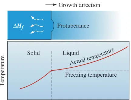
Planar Growth
When a well-inoculated liquid (i.e., a liquid containingnucleating agents) cools under equilibrium conditions, there is no need for undercool-ing since heterogeneous nucleation can occur. Therefore, the temperature of the liquid ahead of the solidification front(i.e., solid-liquid interface) is greater than the freezing
temperature. The temperature of the solid is at or below the freezing temperature. During solidification, the latent heat of fusion is removed by conduction from the solid-liquid interface. Any small protuberance that begins to grow on the interface is surrounded by liquid above the freezing temperature (Figure 9-3). The growth of the protuberance then stops until the remainder of the interface catches up. This growth mechanism, known as planar growth, occurs by the movement of a smooth
solid-liquid interface into the liquid.
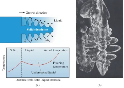
Dendritic Growth
When the liquid is not inoculated and the nucleation ispoor, the liquid has to be undercooled before the solid forms (Figure 9-4). Under these conditions, a small solid protuberance called a dendrite, which forms at the interface, is
encouraged to grow since the liquid ahead of the solidification front is undercooled. The word dendrite comes from the Greek word dendronthat means tree. As the solid dendrite
grows, the latent heat of fusion is conducted into the undercooled liquid, raising the tem-perature of the liquid toward the freezing temtem-perature. Secondary and tertiary dendrite arms can also form on the primary stalks to speed the evolution of the latent heat. Dendritic growth continues until the undercooled liquid warms to the freezing tempera-ture. Any remaining liquid then solidifies by planar growth. The difference between pla-nar and dendritic growth arises because of the different sinks for the latent heat of fusion. The container or mold must absorb the heat in planar growth, but the undercooled liquid absorbs the heat in dendritic growth.
In pure metals, dendritic growth normally represents only a small fraction of the total growth and is given by
(9-3)
where cis the specific heat of the liquid. The numerator represents the heat that the
undercooled liquid can absorb, and the latent heat in the denominator represents the total heat that must be given up during solidification. As the undercooling #Tincreases,
Dendritic fraction = f = c¢T ¢Hf Figure 9-3
more dendritic growth occurs. If the liquid is well-inoculated, undercooling is almost zero and growth would be mainly via the planar front solidification mechanism.
9-5
Solidification Time and Dendrite Size
The rate at which growth of the solid occurs depends on the cooling rate, or the rate of heat extraction. A higher cooling rate produces rapid solidification, or short solidifica-tion times. The time tsrequired for a simple casting to solidify completely can be
calcu-lated using Chvorinov’s rule:
(9-4)
where Vis the volume of the casting and represents the amount of heat that must be removed
before freezing occurs, Ais the surface area of the casting in contact with the mold and
rep-resents the surface from which heat can be transferred away from the casting, nis a constant
(usually about 2), and B is the mold constant. The mold constant depends on the properties
and initial temperatures of both the metal and the mold. This rule basically accounts for the geometry of a casting and the heat transfer conditions. The rule states that, for the same con-ditions, a casting with a small volume and relatively large surface area will cool more rapidly.
ts = Ba
V Ab
n
9 - 5 Solidification Time and Dendrite Size 339
Example 9-2
Redesign of a Casting for Improved StrengthYour company currently is producing a disk-shaped brass casting 2 in. thick and 18 in. in diameter. You believe that by making the casting solidify 25% faster the improvement in the tensile properties of the casting will permit the casting to be made lighter in weight. Design the casting to permit this. Assume that the mold con-stant is 22 min>in.2for this process and n=2.
SOLUTION
One approach would be to use the same casting process, but reduce the thickness of the casting. The thinner casting would solidify more quickly and, because of the faster cooling, should have improved mechanical properties. Chvorinov’s rule helps us cal-culate the required thickness. Ifdis the diameter and xis the thickness of the casting,
then the volume, surface area, and solidification time of the 2-in. thick casting are
V=(%>4)d2x=(%>4)(18)2(2)=508.9 in.3
A=2(%>4)d2+%dx=2(%>4)(18)2+%(18)(2)=622 in.2
The solidification time trof the redesigned casting should be 25% shorter than the
current time:
tr=0.75t=(0.75)(14.73)=11.05 min
Since the casting conditions have not changed, the mold constant B is unchanged. The V>Aratio of the new casting is
Ifxis the required thickness for our redesigned casting, then
Therefore, x=1.68 in.
This thickness provides the required solidification time, while reducing the overall weight of the casting by more than 15%.
Solidification begins at the surface, where heat is dissipated into the surrounding mold material. The rate of solidification of a casting can be described by how rapidly the thickness dof the solidified skin grows:
(9-5)
where tis the time after pouring, ksolidificationis a constant for a given casting material and
mold, and c1is a constant related to the pouring temperature.
d = ksolidification1t - c1
Vr
Ar
= (p>4)d
2x
2(p>4)d2 + pdx =
(p>4)(18)2(x)
2(p>4)(18)2 + p(18)(x) = 0.709 in. aVr
Arb 2
= 0.502 in.2 or Vr
Ar =
0.709 in.
tr = Ba
Vr
Arb 2
= (22)aVr
Arb 2
= 11.05 min
t = BaV
Ab
2
= (22)a508.9622 b
2
Effect on Structure and Properties
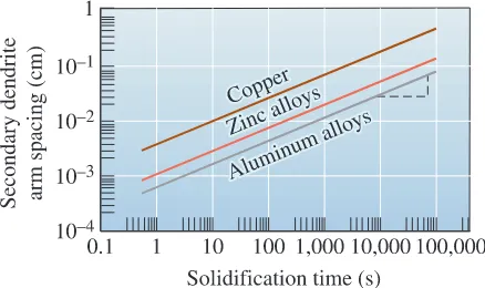
The solidification time affects the size of the dendrites. Normally, dendrite size is characterized by measuring the distance between the secondary dendrite arms (Figure 9-5). The secondary dendrite arm spacing(SDAS) is reduced when the casting freezes more rapidly. The finer, moreexten-sive dendritic network serves as a more efficient conductor of the latent heat to the under-cooled liquid. The SDAS is related to the solidification time by
(9-6)
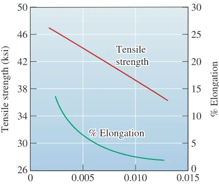
where m and k are constants depending on the composition of the metal. This relation-ship is shown in Figure 9-6 for several alloys. Small secondary dendrite arm spacings are associated with higher strengths and improved ductility (Figure 9-7).
Rapid solidification processing is used to produce exceptionally fine secondary dendrite arm spacings; a common method is to produce very fine liquid droplets that freeze into solid particles. This process is known as spray atomization. The tiny droplets freeze at a rate of about 104°C>s, producing powder particles that range from
!5–100
(m. This cooling rate is not rapid enough to form a metallic glass, but does produce a fine
dendritic structure. By carefully consolidating the solid droplets by powder metallurgy processes, improved properties in the material can be obtained. Since the particles are
SDAS = kts m
Figure 9-5 (a) The secondary dendrite arm spacing (SDAS). (b) Dendrites in an aluminum alloy (* 50). (From ASM Handbook, Vol. 9, Metallography and Microstructure (1985), ASM International, Materials Park, OH 44073-0002.)
Figure 9-6
9 - 5 Solidification Time and Dendrite Size 341
derived from a melt, many complex alloy compositions can be produced in the form of chemically homogenous powders.
The following three examples discuss how Chvorinov’s rule, the relationship between SDAS and the time of solidification, and the SDAS and mechanical properties can be used to design casting processes.
Figure 9-7
The effect of the secondary dendrite arm spacing on the mechanical properties of an aluminum casting alloy.
Example 9-3
Secondary Dendrite Arm Spacing for Aluminum AlloysDetermine the constants in the equation that describe the relationship between secondary dendrite arm spacing and solidification time for aluminum alloys (Figure 9-6).
SOLUTION
We could obtain the value of SDAS at two times from the graph and calculate k and m using simultaneous equations; however, if the scales on the ordinate and abscissa are equal for powers of ten (as in Figure 9-6), we can obtain the slope m from the log-log plot by directly measuring the slope of the graph. In Figure 9-6, we can mark five equal units on the vertical scale and 12 equal units on the horizontal scale. The slope is
The constant k is the value of SDAS when ts=1 s, since
log SDAS=log k m log ts
Ifts=1 s, m log ts=0, and SDAS=k, from Figure 9-6:
k = 7 * 10-4cms +
Example 9-4
Time of SolidificationA 4-in.-diameter aluminum bar solidifies to a depth of 0.5 in. beneath the surface in 5 minutes. After 20 minutes, the bar has solidified to a depth of 1.5 in. How much time is required for the bar to solidify completely?
SOLUTION
From our measurements, we can determine the constants ksolidification and c1 in
Equation 9-5:
Solidification is complete when d=2 in. (half the diameter, since freezing is
occur-ring from all surfaces):
t=31.25 min
In actual practice, we would find that the total solidification time is somewhat longer than 31.25 min. As solidification continues, the mold becomes hotter and is less effective in removing heat from the casting.
1t = 20.447+ 0.5 = 5.59
2 = 0.4471t - 0.5
c1 = (0.447)15 - 0.5 = 0.5 in.
ksolidification = 4.4721.5 - 0.5
- 2.236 = 0.447
in.
1min
1.5 = ksolidification(120 - 15) + 0.5
1.5 in. = ksolidification1(20 min) - c1 = k120 - ( k15 - 0.5)
0.5 in. = ksolidification1(5 min) - c1 or c1 = k15 - 0.5
Example 9-5
Design of an Aluminum Alloy CastingDesign the thickness of an aluminum alloy casting with a length of 12 in., a width of 8 in., and a tensile strength of 40,000 psi. The mold constant in Chvorinov’s rule for aluminum alloys cast in a sand mold is 45 min>in2. Assume that data shown in
Figures 9-6 and 9-7 can be used.
SOLUTION
In order to obtain a tensile strength of 42,000 psi, a secondary dendrite arm spac-ing of about 0.007 cm is required (see Figure 9-7). From Figure 9-6 we can deter-mine that the solidification time required to obtain this spacing is about 300 s or 5 minutes.
From Chvorinov’s rule
ts = Ba
V Ab
9 - 6 Cooling Curves 343
where B=45 min>in.2and xis the thickness of the casting. Since the length is 12 in.
and the width is 8 in.,
9-6
Cooling Curves
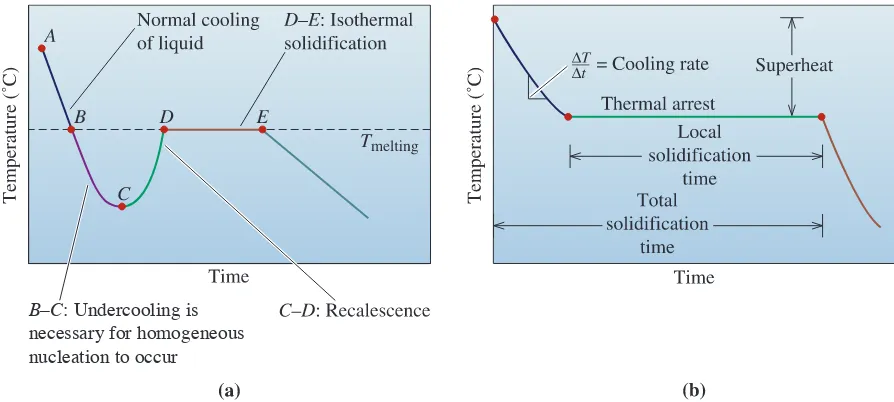
We can summarize our discussion at this point by examining cooling curves. A cooling curve shows how the temperature of a material (in this case, a pure metal) decreases with time [Figure 9-8 (a) and (b)]. The liquid is poured into a mold at the pouring temperature, point A. The difference between the pouring temperature and the freezing temperature is
the superheat. The specific heat is extracted by the mold until the liquid reaches the freez-ing temperature (point B). If the liquid is not well-inoculated, it must be undercooled
x = 0.77 in. 96x = 13.33x + 64 96x
40x + 192 = 1(5>45) = 0.333
5 min = (45 min>in.2)a40 96x
x + 192b
2
A = (2)(8)(12) + (2)(x)(8) + (2)(x)(12) = 40x + 192
V = (8)(12)(x) = 96x
B–C: Undercooling is
necessary for homogeneous nucleation to occur
Figure 9-8 (a) Cooling curve for a pure metal that has not been well-inoculated. The liquid cools as specific heat is removed (between points A and B). Undercooling is thus necessary (between points B and C). As the nucleation begins (point C), latent heat of fusion is released causing an increase in the temperature of the liquid. This process is known as recalescence (point C to point D). The metal continues to solidify at a constant temperature (Tmelting). At point E, solidification is complete. The solid casting continues to cool from this point.
(point Bto C). The slope of the cooling curve before solidification begins is the cooling
rate . As nucleation begins (point C), latent heat of fusion is given off, and the
tem-perature rises. This increase in temtem-perature of the undercooled liquid as a result of nucle-ation is known as recalescence(point Cto D). Solidification proceeds isothermally at the
melting temperature (point Dto E) as the latent heat given off from continued
solidifica-tion is balanced by the heat lost by cooling. This region between points Dand E, where
the temperature is constant, is known as the thermal arrest. A thermal arrest, or plateau,
is produced because the evolution of the latent heat of fusion balances the heat being lost because of cooling. At point E, solidification is complete, and the solid casting cools from
point Eto room temperature.
If the liquid is well-inoculated, the extent of undercooling and recalescence is usu-ally very small and can be observed in cooling curves only by very careful measurements. If effective heterogeneous nuclei are present in the liquid, solidification begins at the freezing temperature [Figure 9-8 (b)]. The latent heat keeps the remaining liquid at the freezing tem-perature until all of the liquid has solidified and no more heat can be evolved. Growth under these conditions is planar. The total solidification timeof the casting is the time required to
remove both the specific heat of the liquid and the latent heat of fusion. Measured from the time of pouring until solidification is complete, this time is given by Chvorinov’s rule. The
local solidification timeis the time required to remove only the latent heat of fusion at a
par-ticular location in the casting; it is measured from when solidification begins until solidifi-cation is completed. The local solidifisolidifi-cation times (and the total solidifisolidifi-cation times) for liquids solidified via undercooled and inoculated liquids will be slightly different.
We often use the terms “melting temperature” and “freezing temperature” while discussing solidification. It would be more accurate to use the term “melting tempera-ture” to describe when a solid turns completely into a liquid. For pure metals and com-pounds, this happens at a fixed temperature (assuming fixed pressure) and without superheating. “Freezing temperature” or “freezing point” can be defined as the tempera-ture at which solidification of a material is complete.
9-7
Cast Structure
In manufacturing components by casting, molten metals are often poured into molds and permitted to solidify. The mold produces a finished shape, known as a casting. In other
cases, the mold produces a simple shape called an ingot. An ingot usually requires
exten-sive plastic deformation before a finished product is created. A macrostructuresometimes
referred to as the ingot structure, consists of as many as three regions (Figure 9-9). (Recall
that in Chapter 2 we used the term “macrostructure” to describe the structure of a mate-rial at a macroscopic scale. Hence, the term “ingot structure” may be more appropriate.)
Chill Zone
The chill zoneis a narrow band of randomly oriented grains at thesur-face of the casting. The metal at the mold wall is the first to cool to the freezing temperature. The mold wall also provides many surfaces at which heterogeneous nucleation takes place.
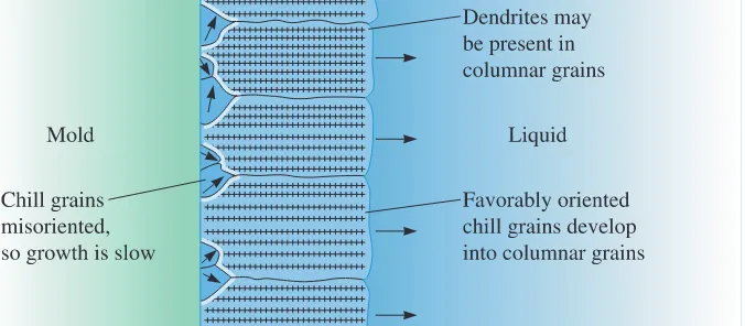
Columnar Zone
The columnar zonecontains elongated grains oriented in aparticular crystallographic direction. As heat is removed from the casting by the mold material, the grains in the chill zone grow in the direction opposite to that of the heat
¢T
9 - 7 Cast Structure 345
flow, or from the coldest toward the hottest areas of the casting. This tendency usually means that the grains grow perpendicular to the mold wall.
Grains grow fastest in certain crystallographic directions. In metals with a cubic crystal structure, grains in the chill zone that have a 81009direction perpendicular to the mold wall grow faster than other less favorably oriented grains (Figure 9-10). Eventually, the grains in the columnar zone have 81009directions that are parallel to one another, giv-ing the columnar zone anisotropic properties. This formation of the columnar zone is
Figure 9-9
Development of the ingot structure of a casting during solidification: (a) nucleation begins, (b) the chill zone forms, (c) preferred growth produces the columnar zone, and (d) additional nucleation creates the equiaxed zone.
influenced primarily by growth—rather than nucleation—phenomena. The grains may be composed of many dendrites if the liquid is originally undercooled. The solidification may proceed by planar growth of the columnar grains if no undercooling occurs.
Equiaxed Zone
Although the solid may continue to grow in a columnarman-ner until all of the liquid has solidified, an equiaxed zone frequently forms in the center of the casting or ingot. The equiaxed zonecontains new, randomly oriented grains, often
caused by a low pouring temperature, alloying elements, or grain refining or inoculating agents. Small grains or dendrites in the chill zone may also be torn off by strong convec-tion currents that are set up as the casting begins to freeze. These also provide heteroge-neous nucleation sites for what ultimately become equiaxed grains. These grains grow as relatively round, or equiaxed, grains with a random orientation, and they stop the growth of the columnar grains. The formation of the equiaxed zone is a nucleation-controlled process and causes that portion of the casting to display isotropic behavior.
By understanding the factors that influence solidification in different regions, it is possible to produce castings that first form a “skin” of a chill zone and then dendrites. Metals and alloys that show this macrostructure are known as skin-forming alloys. We
also can control the solidification such that no skin or advancing dendritic arrays of grains are seen; columnar to equiaxed switchover is almost at the mold walls. The result is a cast-ing with a macrostructure consistcast-ing predominantly of equiaxed grains. Metals and alloys that solidify in this fashion are known as mushy-forming alloyssince the cast material
seems like a mush of solid grains floating in a liquid melt. Many aluminum and magne-sium alloys show this type of solidification. Often, we encourage an all-equiaxed structure and thus create a casting with isotropic properties by effective grain refinement or inocu-lation. In a later section, we will examine one case (turbine blades) where we control solid-ification to encourage all columnar grains and hence anisotropic behavior.
Cast ingot structure and microstructure are important particularly for compo-nents that are directly cast into a final shape. In many situations though, as discussed in Section 9-1, metals and alloys are first cast into ingots, and the ingots are subsequently subjected to thermomechanical processing (e.g., rolling, forging etc.). During these steps, the cast macrostructure is broken down and a new microstructure will emerge, depending upon the thermomechanical process used (Chapter 8).
9-8
Solidification Defects
Although there are many defects that potentially can be introduced during solidification, shrinkage and porosity deserve special mention. If a casting contains pores (small holes), the cast component can fail catastrophically when used for load-bearing applications (e.g., turbine blades).
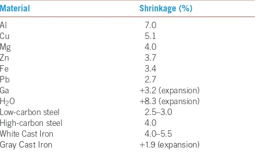
Shrinkage
Almost all materials are more dense in the solid state than in the liquidstate. During solidification, the material contracts, or shrinks, as much as 7% (Table 9-2). Often, the bulk of the shrinkageoccurs as cavities, if solidification begins at all
surfaces of the casting, or pipes, if one surface solidifies more slowly than the others
9 - 8 Solidification Defects 347
A common technique for controlling cavityand pipe shrinkageis to place a riser,
or an extra reservoir of metal, adjacent and connected to the casting. As the casting solid-ifies and shrinks, liquid metal flows from the riser into the casting to fill the shrinkage void. We need only to ensure that the riser solidifies after the casting and that there is an internal liquid channel that connects the liquid in the riser to the last liquid to solidify in the casting. Chvorinov’s rule can be used to help design the size of the riser. The follow-ing example illustrates how risers can be designed to compensate for shrinkage.
TABLE 9-2■Shrinkage during solidification for selected materials
Material Shrinkage (%)
Al 7.0
Cu 5.1
Mg 4.0
Zn 3.7
Fe 3.4
Pb 2.7
Ga +3.2 (expansion) H2O +8.3 (expansion)
Low-carbon steel 2.5–3.0 High-carbon steel 4.0 White Cast Iron 4.0–5.5
Gray Cast Iron +1.9 (expansion)
Note: Some data from DeGarmo, E. P., Black, J. T., and Koshe, R. A. Materials and Processes in Manufacturing, Prentice Hall, 1997.
Figure 9-11
Several types of macroshrinkage can occur, including cavities and pipes. Risers can be used to help
compensate for shrinkage.
Example 9-6
Design of a Riser for a CastingDesign a cylindrical riser, with a height equal to twice its diameter, that will compen-sate for shrinkage in a 2 cm*8 cm*16 cm, casting (Figure 9-12).
Figure 9-12
SOLUTION
We know that the riser must freeze after the casting. To be conservative, we typ-ically require that the riser take 25% longer to solidify than the casting. Therefore,
The subscripts rand cstand for riser and casting, respectively. The mold constant
B is the same for both casting and riser, so
The volume of the casting is
Vc=(2 cm)(8 cm)(16 cm)=256 cm3
The area of the riser adjoined to the casting must be subtracted from the total surface area of the casting in order to calculate the surface area of the casting in contact with the mold:
where Dis the diameter of the cylindrical riser. We can write equations for the
vol-ume and area of the cylindrical riser, noting that the cylinder height H=2D:
where again we have not included the area of the riser adjoined to the casting in the area calculation. The volume to area ratio of the riser is given by
and must be greater than that of the casting according to
Substituting,
Solving for the smallest diameter for the riser:
D=3.78 cm
Although the volume of the riser is less than that of the casting, the riser solidifies more slowly because of its compact shape.
2
9D 7 11.25a
256 cm3 352 cm2 - pD2>4b aVAb
r =
2
9D 7 11.25a
V Abc
aVAb
r =
(pD3>2)
(9pD2>4) =
2 9D
Ar = pD2
4 + pDH =
pD2
4 + pD(2D) = 9 4pD
2
Vr = pD
2
4 H =
pD2
4 (2D) =
pD3
2
Ac = (2)(2 cm)(8 cm)+(2)(2 cm)(16 cm)+(2)(8 cm)(16 cm) - pD
2
4 = 352 cm2
-pD2
4 aV
Abr =
11.25aV
Abc
tr = 1.25tc or BaV
Ab
2
r = 1.25 Ba
V Abc
9 - 8 Solidification Defects 349
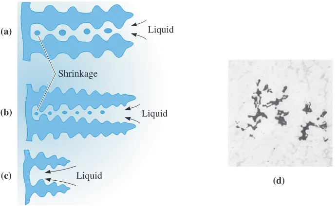
Interdendritic Shrinkage
This consists of small shrinkage poresbetween dendrites (Figure 9-13). This defect, also called microshrinkage or shrinkage porosity, is difficult to prevent by the use of risers. Fast cooling rates may reduce problems
with interdendritic shrinkage; the dendrites may be shorter, permitting liquid to flow
through the dendritic network to the solidifying solid interface. In addition, any shrink-age that remains may be finer and more uniformly distributed.
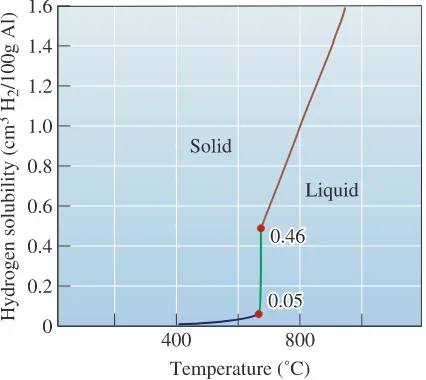
Gas Porosity
Many metals dissolve a large quantity of gas when they aremolten. Aluminum, for example, dissolves hydrogen. When the aluminum solidifies, how-ever, the solid metal retains in its crystal structure only a small fraction of the hydrogen since the solubility of the solid is remarkably lower than that of the liquid (Figure 9-14). The excess hydrogen that cannot be incorporated in the solid metal or alloy crystal struc-ture forms bubbles that may be trapped in the solid metal, producing gas porosity. The
amount of gas that can be dissolved in molten metal is given by Sievert’s law:
(9-7)
where pgasis the partial pressure of the gas in contact with the metal and K is a
con-stant which, for a particular metal-gas system, increases with increasing temperature. We can minimize gas porosity in castings by keeping the liquid temperature low, by adding materials to the liquid to combine with the gas and form a solid, or by ensur-ing that the partial pressure of the gas remains low. The latter may be achieved by plac-ing the molten metal in a vacuum chamber or bubblplac-ing an inert gas through the metal. Because pgasis low in the vacuum, the gas leaves the metal, enters the vacuum, and is
Percent of gas = K1pgas
Figure 9-14
The solubility of hydrogen gas in aluminum when the partial pressure of H2=1 atm.
Example 9-7
Design of a Degassing Process for CopperAfter melting at atmospheric pressure, molten copper contains 0.01 weight percent oxygen. To ensure that your castings will not be subject to gas porosity, you want to reduce the weight percent to less than 0.00001% prior to pouring. Design a degassing process for the copper.
SOLUTION
We can solve this problem in several ways. In one approach, the liquid copper is placed in a vacuum chamber; the oxygen is then drawn from the liquid and carried away into the vacuum. The vacuum required can be estimated from Sievert’s law:
1 atm
pvacuum = (1000)
2
or pvacuum = 10-6 atm
0.01%
0.00001% = Aa 1
pvacuumb
% Oinitial
% Ovacuum =
K1p initial
K1p vacuum = Aa
1 atm
pvacuumb
carried away. Gas flushingis a process in which bubbles of a gas, inert or reactive, are
9 - 9 Casting Processes for Manufacturing Components 351
Another approach would be to introduce a copper-15% phosphorous alloy. The phosphorous reacts with oxygen to produce P2O5, which floats out of the liquid, by the reaction:
5O+2P:P2O5
Typically, about 0.01 to 0.02% P must be added remove the oxygen.
In the manufacturing ofstainless steel, a process known as argon oxygen decar-burization(AOD) is used to lower the carbon content of the melt without oxidizing
chromium or nickel. In this process, a mixture of argon (or nitrogen) and oxygen gases is forced into molten stainless steel. The carbon dissolved in the molten steel is oxidized by the oxygen gas via the formation of carbon monoxide (CO) gas; the CO is carried away by the inert argon (or nitrogen) gas bubbles. These processes need very careful control since some reactions (e.g., oxidation of carbon to CO) are exother-mic (generate heat).
9-9
Casting Processes for Manufacturing
Components
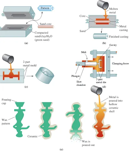
Figure 9-15 summarizes four of the dozens of commercial casting processes. In some processes, the molds can be reused; in others, the mold is expendable. Sand casting
processes include green sand molding, for which silica (SiO2) sand grains bonded with
wet clay are packed around a removable pattern. Ceramic casting processes use a fine-grained ceramic material as the mold, as slurry containing the ceramic may be poured around a reusable pattern, which is removed after the ceramic hardens. In investment casting, the ceramic slurry of a material such as colloidal silica (consisting of ceramic
nanoparticles) coats a wax pattern. After the ceramic hardens (i.e., the colloidal silica dispersion gels), the wax is melted and drained from the ceramic shell, leaving behind a cavity that is then filled with molten metal. After the metal solidifies, the mold is bro-ken to remove the part. The investment casting process, also known as the lost wax process, is suited for generating complex shapes. Dentists and jewelers originally used
the precision investment casting process. Currently, this process is used to produce such components as turbine blades, titanium heads of golf clubs, and parts for knee and hip prostheses. In another process known as the lost foam process, polystyrene beads,
similar to those used to make coffee cups or packaging materials, are used to produce a foam pattern. Loose sand is compacted around the pattern to produce a mold. When molten metal is poured into the mold, the polymer foam pattern melts and decom-poses, with the metal taking the place of the pattern.
Plunger Melt
Cavity
Shot chamber
2-part metal die
Clamping force
9 - 1 0 Continuous Casting and Ingot Casting 353
molds, including those used in investment casting, are good insulators and give the slow-est-cooling and lowest-strength castings. Millions of truck and car pistons are made in foundries using permanent mold casting. Good surface finish and dimensional accuracy are the advantages of permanent mold castingtechniques. High mold costs and limited
complexity in shape are the disadvantages.
In pressure die casting, molten metallic material is forced into the mold under
high pressures and is held under pressure during solidification. Many zinc, aluminum, and magnesium-based alloys are processed using pressure die casting. Extremely smooth surface finishes, very good dimensional accuracy, the ability to cast intricate shapes, and high production rates are the advantages of the pressure die casting process. Since the mold is metallic and must withstand high pressures, the dies used are expensive and the technique is limited to smaller sized components.
9-10
Continuous Casting and Ingot Casting
As discussed in the prior section, casting is a tool used for the manufacturing of components. It is also a process for producing ingots or slabs that can be further processed into different shapes (e.g., rods, bars, wires, etc.). In the steel industry, millions of pounds of steels are produced using blast furnaces, electric arc furnaces and other processes. Figure 9-16 shows
Figure 9-17
Vertical continuous casting, used in producing many steel products. Liquid metal contained in the tundish partially solidifies in a mold.
a summary of steps to extract steels using iron ores, coke, and limestone. Although the details change, most metals and alloys (e.g., copper and zinc) are extracted from their ores using similar processes. Certain metals, such as aluminum, are produced using an electrolytic process since aluminum oxide is too stable and cannot be readily reduced to aluminum metal using coke or other reducing agents.
In many cases, we begin with scrap metals and recyclable alloys. In this case, the scrap metal is melted and processed, removing the impurities and adjusting the composi-tion. Considerable amounts of steel, aluminum, zinc, stainless steel, titanium, and many other materials are recycled every year.
In ingot casting, molten steels or alloys obtained from a furnace are cast into large
molds. The resultant castings, called ingots, are then processed for conversion into useful shapes via thermomechanical processing, often at another location. In the continuous castingprocess, the idea is to go from molten metallic material to some more useful
“semi-finished” shape such as a plate, slab, etc. Figure 9-17 illustrates a common method for producing steel plate and bars. The liquid metal is fed from a holding vessel (a tundish) into a water-cooled oscillating copper mold, which rapidly cools the surface of the steel. The partially solidified steel is withdrawn from the mold at the same rate that additional liquid steel is introduced. The center of the steel casting finally solidifies well after the casting exits the mold. The continuously cast material is then cut into appropriate lengths by special cutting machines.
Continuous casting is cost effective for processing many steels, stainless steels, and aluminum alloys. Ingot casting is also cost effective and used for many steels where a continuous caster is not available or capacity is limited and for alloys of non-ferrous met-als (e.g., zinc, copper) where the volumes are relatively small and the capital expenditure needed for a continuous caster may not be justified. Also, not all alloys can be cast using the continuous casting process.
9 - 1 0 Continuous Casting and Ingot Casting 355
Figure 9-18 Secondary processing steps in processing of steel and alloys. (Source www.steel.org. Used with permission of the American Iron and Steel Institute.)
Example 9-8
Design of a Continuous Casting MachineFigure 9-19 shows a method for continuous casting of 0.25-in.-thick, 48-in.-wide aluminum plate that is subsequently rolled into aluminum foil. The liquid aluminum is introduced between two large steel rolls that slowly turn. We want the aluminum to be completely solidified by the rolls just as the plate emerges from the machine. The rolls act as a permanent mold with a mold constant Bof about 5 min>in.2when
the aluminum is poured at the proper superheat. Design the rolls required for this process.
SOLUTION
It would be helpful to simplify the geometry so that we can determine a solidification time for the casting. Let’s assume that the shaded area shown in Figure 9-19(b) represents the casting and can be approximated by the average thickness times a length and width. The average thickness is (0.50 in.+0.25 in.)>2 =0.375 in. Then
Only the area directly in contact with the rolls is used in Chyorinov’s rule, since little or no heat is transferred from other surfaces. The solidification time should be
For the plate to remain in contact with the rolls for this period of time, the diame-ter of the rolls and the rate of rotation of the rolls must be properly specified. Figure 9-19(c) shows that the angle 'between the points where the liquid enters
and exits the rolls is
The surface velocity of the rolls is the product of the circumference and the rate of rotation of the rolls, v=%DR, where Rhas units of revolutions>minute. The velocity vis also the rate at which we can produce the aluminum plate. The time required for the rolls to travel the distance lmust equal the required solidifi-cation time:
The length lis the fraction of the roll diameter that is in contact with the aluminum during freezing and can be given by
Note that has units of degrees. Then, by substituting for land vin the equation for
the time:
A number of combinations ofDand Rprovide the required solidification rate. Let’s
calculate 'for several diameters and then find the required R. R = (360)(0.1758)u = .0158 u rev>min
t = l
v =
pDu
360pDR = u
360 R = 0.1758 min
u
l = p360 Du
t = l
v = 0.1758 min
cos u = (D>2) - 0.125
(D>2) =
D - 0.25
D ts = Ba
V Ab
2
= (5)(0.1875)2 = 0.1758 min
V A =
0.375lw
9 - 1 1 Directional Solidification [DS], Single Crystal Growth, and Epitaxial Growth 357
D (in.) ''(°) I (in.) R 0.0159''(rev>>min) v %DR (in.>>min)
24 8.28 1.73 0.131 9.86
36 6.76 2.12 0.107 12.1
48 5.85 2.45 0.092 13.9
60 5.23 2.74 0.083 15.6
As the diameter of the rolls increases, the contact area (l) between the rolls
and the metal increases. This, in turn, permits a more rapid surface velocity (v) of the
rolls and increases the rate of production of the plate. Note that the larger diame-ter rolls do not need to rotate as rapidly to achieve these higher velocities.
In selecting our final design, we prefer to use the largest practical roll diam-eter to ensure high production rates. As the rolls become more massive, however, they and their supporting equipment become more expensive.
In actual operation of such a continuous caster, faster speeds could be used, since the plate does not have to be completely solidified at the point where it emerges from the rolls.
9-11
Directional Solidification [DS], Single Crystal
Growth, and Epitaxial Growth
There are some applications for which a small equiaxed grain structure in the casting is not desired. Castings used for blades and vanes in turbine engines are an example (Figure 9-20). These castings are often made of titanium, cobalt, or nickel-based super alloys using preci-sion investment casting.
= =
In conventionally cast parts, an equiaxed grain structure is often produced; how-ever, blades and vanes for turbine and jet engines fail along transverse grain boundaries. Better creep and fracture resistance are obtained using the directional solidification(DS)
growth technique. In the DS process, the mold is heated from one end and cooled from the other, producing a columnar microstructure with all of the grain boundaries running in the longitudinal direction of the part. No grain boundaries are present in the transverse direction [Figure 9-20(b)].
Still better properties are obtained by using a single crystal (SC) technique,
Solidification of columnar grains again begins at a cold surface; however, due to a helical cavity in the mold between the heat sink and the main mold cavity, only one columnar grain is able to grow to the main body of the casting [Figure 9-20(c)]. The single-crystal casting has no grain boundaries, so its crystallographic planes and directions can be directed in an optimum orientation.
Single Crystal Growth
One of the most important applications ofsolidification is the growth of single crystals. Polycrystalline materials cannot be used effectively in many electronic and optical applications. Grain boundaries and other defects interfere with the mechanisms that provide useful electrical or optical functions. For example, in order to utilize the semiconducting behavior of doped silicon, high-purity single crystals must be used. The current technology for silicon makes use of large (up to 12 in. diameter) single crystals. Typically, a large crystal of the material is grown [Figure 9-21(a)]. The large crystal is then cut into silicon wafers that are only a few mil-limeters thick [Figure 9-21(b)]. The Bridgmanand Czochralski processesare some of the
popular methods used for growing single crystals of silicon, GaAs, lithium niobate (LiNbO3), and many other materials.
Crystal growth furnaces containing molten materials must be maintained at a pre-cise and stable temperature. Often, a small crystal of a predetermined crystallographic ori-entation is used as a “seed.” Heat transfer is controlled so that the entire melt crystallizes into a single crystal. Typically, single crystals offer considerably improved, controllable,
Figure 9-21 (a) Silicon single crystal (Courtesy of Dr. A. J. Deardo, Dr. M. Hua and Dr. J. Garcia) and (b) silicon wafer. (Steve McAlister/Stockbyte/Getty Images.)
9 - 1 2 Solidification of Polymers and Inorganic Glasses 359
and predictable properties at a higher cost than polycrystalline materials. With a large demand, however, the cost of single crystals may not be a significant factor compared to the rest of the processing costs involved in making novel and useful devices.
Epitaxial Growth
There are probably over a hundred processes for thedep-osition of thin films materials. In some of these processes, there is a need to control the texture or crystallographic orientation of the polycrystalline material being deposited; others require a single crystal film oriented in a particular direction. If this is the case, we can make use of a substrate of a known orientation. Epitaxy is the process by which one material is made to grow in an oriented fashion using a substrate that is crystallographi-cally matched with the material being grown. If the lattice matching between the substrate and the film is good (within a few %), it is possible to grow highly oriented or single crys-tal thin films. This is known as epitaxial growth.
9-12
Solidification of Polymers and Inorganic
Glasses
Many polymers do not crystallize, but solidify, when cooled. In these materials, the ther-modynamic driving force for crystallization may exist; however, the rate of nucleation of the solid may be too slow or the complexity of the polymer chains may be so great that a crystalline solid does not form. Crystallization in polymers is almost never complete and is significantly different from that of metallic materials, requiring long polymer chains to become closely aligned over relatively large distances. By doing so, the polymer grows as
lamellar, or plate-like, crystals (Figure 9-22). The region between each lamella contains
polymer chains arranged in an amorphous manner. In addition, bundles of lamellae grow from a common nucleus, but the crystallographic orientation of the lamellae within any one bundle is different from that in another. As the bundles grow, they may produce a
Figure 9-22
spheroidal shape called a spherulite. The spherulite is composed of many individual
bun-dles of differently oriented lamellae. Amorphous regions are present between the individ-ual lamellae, bundles of lamellae, and individindivid-ual spherulites.
Many polymers of commercial interest develop crystallinity during their process-ing. Crystallinity can originate from cooling as discussed previously, or from the applica-tion of stress. For example, we have learned how PET plastic bottles are prepared using the blow-stretch process (Chapter 3) and how they can develop considerable crystallinity during formation. This crystallization is a result of the application of stress, and thus, is different from that encountered in the solidification of metals and alloys. In general, poly-mers such as nylon and polyethylene crystallize more easily compared to many other ther-moplastics.
Inorganic glasses, such as silicate glasses, also do not crystallize easily for kinetic reasons. While the thermodynamic driving force exists, similar to the solidification of met-als and alloys, the melts are often too viscous and the diffusion is too slow for crystalliza-tion to proceed during solidificacrystalliza-tion. The float-glass process is used to melt and cast large flat pieces of glasses. In this process, molten glass is made to float on molten tin. As dis-cussed in Chapter 7, since the strength of inorganic glasses depends critically on surface flaws produced by the manufacturing process or the reaction with atmospheric moisture, most glasses are strengthened using tempering. When safety is not a primary concern, annealing is used to reduce stresses. Long lengths of glass fibers, such as those used with fiber optics, are produced by melting a high-purity glass rod known as a preform. As
men-tioned earlier, careful control of nucleation in glasses can lead to glass-ceramics, colored glasses, and photochromic glasses (glasses that can change their color or tint upon expo-sure to sunlight).
9-13
Joining of Metallic Materials
In brazing, an alloy, known as a filler, is used to join one metal to itself or to another
metal. The brazing filler metal has a melting temperature above about 450°C. Soldering
is a brazing process in which the filler has a melting temperature below 450°C. Lead-tin and antimony-tin alloys are the most common materials used for soldering. Currently, there is a need to develop lead-free soldering materials due to the toxicity of lead. Alloys being developed include those that are based on Sn-Cu-Ag. In brazing and soldering, the metallic materials being joined do not melt; only the filler material melts. For both braz-ing and solderbraz-ing, the composition of the filler material is different from that of the base material being joined. Various aluminum-silicon, copper, magnesium, and precious met-als are used for brazing.
Solidification is also important in the joining of metals through fusion welding.
In the fusion-welding processes, a portion of the metals to be joined is melted and, in many instances, additional molten filler metal is added. The pool of liquid metal is called the fusion zone(Figures 9-23 and 9-24). When the fusion zone subsequently solidifies, the
original pieces of metal are joined together. During solidification of the fusion zone, nucle-ation is not required. The solid simply begins to grow from existing grains, frequently in a columnar manner.
9 - 1 3 Joining of Metallic Materials 361
increased thickness of the metal, smaller fusion zones, low original metal temperatures, and certain types of welding processes. Oxyacetylene welding, for example, uses a rel-atively low-intensity heat source; consequently, welding times are long and the sur-rounding solid metal, which becomes very hot, is not an effective heat sink. Arc-welding processes provide a more intense heat source, thus reducing heating of the surround-ing metal and providsurround-ing faster coolsurround-ing. Laser weldsurround-ing and electron-beam weldsurround-ing are exceptionally intense heat sources and produce very rapid cooling rates and potentially strong welds. The friction stir welding process has been developed for Al and Al-Li alloys for aerospace applications.
(a)
(b)
(c)
Figure 9-23
A schematic diagram of the fusion zone and solidification of the weld during fusion welding: (a) initial prepared joint, (b) weld at the maximum temperature, with joint filled with filler metal, and (c) weld after solidification.
Figure 9-24
Summary
• Transformation of a liquid to a solid is probably the most important phase transfor-mation in applications of materials science and engineering.
• Solidification plays a critical role in the processing of metals, alloys, thermoplastics, and inorganic glasses. Solidification is also important in techniques used for the joining of metallic materials.
• Nucleation produces a critical-size solid particle from the liquid melt. Formation of nuclei is determined by the thermodynamic driving force for solidification and is opposed by the need to create the solid-liquid interface. As a result, solidification may not occur at the freezing temperature.
• Homogeneous nucleation requires large undercoolings of the liquid and is not observed in normal solidification processing. By introducing foreign particles into the liquid, nuclei are provided for heterogeneous nucleation. This is done in practice by inocula-tion or grain refining. This process permits the grain size of the casting to be controlled.
• Rapid cooling of the liquid can prevent nucleation and growth, producing amorphous solids, or glasses, with unusual mechanical and physical properties. Polymeric, metal-lic, and inorganic materials can