ALKYLATION AND
POLYMERIZATION
P
●A
●R
●T
●1
1.3
CHAPTER 1.1
NExOCTANE™ TECHNOLOGY
FOR ISOOCTANE
PRODUCTION
Ronald Birkhoff
Kellogg Brown & Root, Inc. (KBR)Matti Nurminen
Fortum Oil and Gas OyINTRODUCTION
Environmental issues are threatening the future use of MTBE (methyl-tert-butyl ether) in gasoline in the United States. Since the late 1990s, concerns have arisen over ground and drinking water contamination with MTBE due to leaking of gasoline from underground storage tanks and the exhaust from two-cycle engines. In California a number of cases of drinking water pollution with MTBE have occurred. As a result, the elimination of MTBE in gasoline in California was mandated, and legislation is now set to go in effect by the end of 2003. The U.S. Senate has similar law under preparation, which would eliminate MTBE in the 2006 to 2010 time frame.
With an MTBE phase-out imminent, U.S. refiners are faced with the challenge of replacing the lost volume and octane value of MTBE in the gasoline pool. In addition, uti-lization of idled MTBE facilities and the isobutylene feedstock result in pressing problems of unrecovered and/or underutilized capital for the MTBE producers. Isooctane has been identified as a cost-effective alternative to MTBE. It utilizes the same isobutylene feeds used in MTBE production and offers excellent blending value. Furthermore, isooctane pro-duction can be achieved in a low-cost revamp of an existing MTBE plant. However, since isooctane is not an oxygenate, it does not replace MTBE to meet the oxygen requirement currently in effect for reformulated gasoline.
The NExOCTANE technology was developed for the production of isooctane. In the process, isobutylene is dimerized to produce isooctene, which can subsequently be hydro-genated to produce isooctane. Both products are excellent gasoline blend stocks with sig-nificantly higher product value than alkylate or polymerization gasoline.
1.4 ALKYLATION AND POLYMERIZATION
HISTORY OF MTBE
During the 1990s, MTBE was the oxygenate of choice for refiners to meet increasingly strin-gent gasoline specifications. In the United States and in a limited number of Asian countries, the use of oxygenates in gasoline was mandated to promote cleaner-burning fuels. In addi-tion, lead phase-down programs in other parts of the world have resulted in an increased demand for high-octane blend stock. All this resulted in a strong demand for high-octane fuel ethers, and significant MTBE production capacity has been installed since 1990.
Today, the United States is the largest consumer of MTBE. The consumption increased dramatically with the amendment of the Clean Air Act in 1990 which incorporated the 2 percent oxygen mandate. The MTBE production capacity more than doubled in the 5-year period from 1991 to 1995. By 1998, the MTBE demand growth had leveled off, and it has since tracked the demand growth for reformulated gasoline (RFG). The United States con-sumes about 300,000 BPD of MTBE, of which over 100,000 BPD is consumed in California. The U.S. MTBE consumption is about 60 percent of the total world demand.
MTBE is produced from isobutylene and methanol. Three sources of isobutylene are used for MTBE production:
● On-purpose butane isomerization and dehydrogenation ● Fluid catalytic cracker (FCC) derived mixed C
4fraction ● Steam cracker derived C
4fraction
The majority of the MTBE production is based on FCC and butane dehydrogenation derived feeds.
NExOCTANE BACKGROUND
Fortum Oil and Gas Oy, through its subsidiary Neste Engineering, has developed the NExOCTANE technology for the production of isooctane. NExOCTANE is an extension of Fortum’s experience in the development and licensing of etherification technologies. Kellogg Brown & Root, Inc. (KBR) is the exclusive licenser of NExOCTANE. The tech-nology licensing and process design services are offered through a partnership between Fortum and KBR.
The technology development program was initialized in 1997 in Fortum’s Research and Development Center in Porvoo, Finland, for the purpose of producing high-purity isooctene, for use as a chemical intermediate. With the emergence of the MTBE pollution issue and the pending MTBE phase-out, the focus in the development was shifted in 1998 to the conver-sion of existing MTBE units to produce isooctene and isooctane for gasoline blending.
The technology development has been based on an extensive experimental research program in order to build a fundamental understanding of the reaction kinetics and key product separation steps in the process. This research has resulted in an advanced kinetic modeling capability, which is used in the design of the process for licensees. The process has undergone extensive pilot testing, utilizing a full range of commercial feeds. The first commercial NExOCTANE unit started operation in the third quarter of 2002.
PROCESS CHEMISTRY
The primary reaction in the NExOCTANE process is the dimerization of isobutylene over acidic ion-exchange resin catalyst. This dimerization reaction forms two isomers of
NExOCTANE™ TECHNOLOGY FOR ISOOCTANE PROCUCTION 1.5
trimethylpentene (TMP), or isooctene, namely, 2,4,4-TMP-1 and 2,4,4-TMP-2, according to the following reactions:
TMP further reacts with isobutylene to form trimers, tetramers, etc. Formation of these oligomers is inhibited by oxygen-containing polar components in the reaction mixture. In the
Isobutylene
NExOCTANE process, water and alcohol are used as inhibitors. These polar components block acidic sites on the ion-exchange resin, thereby controlling the catalyst activity and increasing the selectivity to the formation of dimers. The process conditions in the dimer-ization reactions are optimized to maximize the yield of high-quality isooctene product.
A small quantity of C7and C9components plus other C8isomers will be formed when other olefin components such as propylene,n-butenes, and isoamylene are present in the reaction mixture. In the NExOCTANE process, these reactions are much slower than the isobutylene dimerization reaction, and therefore only a small fraction of these components is converted.
Isooctene can be hydrogenated to produce isooctane, according to the following reaction:
CH2 – C – CH2 – C – CH3
The NExOCTANE process consists of two independent sections. Isooctene is produced by dimerization of isobutylene in the dimerization section, and subsequently, the isooctene can be hydrogenated to produce isooctane in the hydrogenation section. Dimerization and hydrogenation are independently operating sections. Figure 1.1.1 shows a simplified flow diagram for the process.
The isobutylene dimerization takes place in the liquid phase in adiabatic reactors over fixed beds of acidic ion-exchange resin catalyst. The product quality, specifically the
bution of dimers and oligomers, is controlled by recirculating alcohol from the product recov-ery section to the reactors. Alcohol is formed in the dimerization reactors through the reaction of a small amount of water with olefin present in the feed. The alcohol content in the reactor feed is typically kept at a sufficient level so that the isooctene product contains less than 10 percent oligomers. The dimerization product recovery step separates the isooctene product from the unreacted fraction of the feed (C4raffinate) and also produces a concentrated alco-hol stream for recycle to the dimerization reaction. The C4raffinate is free of oxygenates and suitable for further processing in an alkylation unit or a dehydrogenation plant.
Isooctene produced in the dimerization section is further processed in a hydrogenation unit to produce the saturated isooctane product. In addition to saturating the olefins, this unit can be designed to reduce sulfur content in the product. The hydrogenation section consists of trickle-bed hydrogenation reactor(s) and a product stabilizer. The purpose of the stabilizer is to remove unreacted hydrogen and lighter components in order to yield a product with a specified vapor pressure.
The integration of the NExOCTANE process into a refinery or butane dehydrogenation complex is similar to that of the MTBE process. NExOCTANE selectively reacts isobuty-lene and produces a C4raffinate which is suitable for direct processing in an alkylation or dehydrogenation unit. A typical refinery integration is shown in Fig. 1.1.2, and an integra-tion into a dehydrogenaintegra-tion complex is shown in Fig. 1.1.3.
NExOCTANE PRODUCT PROPERTIES
The NExOCTANE process offers excellent selectivity and yield of isooctane (2,2,4-trimethylpentane). Both the isooctene and isooctane are excellent gasoline blending compo-nents. Isooctene offers substantially better octane blending value than isooctane. However, the olefin content of the resulting gasoline pool may be prohibitive for some refiners.
The characteristics of the products are dependent on the type of feedstock used. Table 1.1.1 presents the product properties of isooctene and isooctane for products produced from FCC derived feeds as well as isooctane from a butane dehydrogenation feed.
The measured blending octane numbers for isooctene and isooctane as produced from FCC derived feedstock are presented in Table 1.1.2. The base gasoline used in this
analy-1.6 ALKYLATION AND POLYMERIZATION
sis is similar to nonoxygenated CARB base gasoline. Table 1.1.2 demonstrates the signif-icant blending value for the unsaturated isooctene product, compared to isooctane.
PRODUCT YIELD
An overall material balance for the process based on FCC and butane dehydrogenation derived isobutylene feedstocks is shown in Table 1.1.3. In the dehydrogenation case, an isobutylene feed content of 50 wt % has been assumed, with the remainder of the feed NExOCTANE™ TECHNOLOGY FOR ISOOCTANE PROCUCTION 1.7
FCC
ALKYLATION DIMERIZATION
Hydrogen Isooctane
Isooctene
HYDROGENATION
C4 C4 Raffinate
NExOCTANE FIGURE 1.1.2 Typical integration in refinery.
HYDROGE-NATION DEHYDRO
Hydrogen
Isooctane Isooctene
DIMERIZATION iC4=
NExOCTANE
Butane
HYDROGEN TREATMENT
RECYCLE TREATMENT
ISOMERI-ZATION DIB
C4 Raffinate
FIGURE 1.1.3 Integration in a typical dehydrogenation complex.
mostly consisting of isobutane. For the FCC feed an isobutylene content of 22 wt % has been used. In each case the C4raffinate quality is suitable for either direct processing in a refinery alkylation unit or recycle to isomerization or dehydrogenation step in the dehy-drogenation complex. Note that the isooctene and isooctane product rates are dependent on the content of isobutylene in the feedstock.
UTILITY REQUIREMENTS
The utilities required for the NExOCTANE process are summarized in Table 1.1.4.
1.8 ALKYLATION AND POLYMERIZATION
TABLE 1.1.1 NExOCTANE Product Properties
FCC C4 Butane
dehydrogenation Isooctane Isooctene Isooctane
Specific gravity 0.704 0.729 0.701
RONC 99.1 101.1 100.5
MONC 96.3 85.7 98.3
(R⫹M) / 2 97.7 93.4 99.4
RVP, lb/in2absolute 1.8 1.8 1.8
TABLE 1.1.2 Blending Octane Number in CARB Base Gasoline (FCC Derived)
Isooctene Isooctane
Blending BRON BMON (R⫹M) / 2 BRON BMON (R⫹M) / 2
volume, %
10 124.0 99.1 111.0 99.1 96.1 97.6
20 122.0 95.1 109.0 100.1 95.1 97.6
100 101.1 85.7 93.4 99.1 96.3 97.7
TABLE 1.1.3 Sample Material Balance for NExOCTANE Unit
Material balance FCC C4feed, lb/h (BPD) Butane dehydrogenation, lb/h (BPD) Dimerization section:
Hydrocarbon feed 137,523 (16,000) 340,000 (39,315) Isobutylene contained 30,614 (3,500) 170,000 (19,653) Isooctene product 30,714 (2,885) 172,890 (16,375)
C4raffinate 107,183 (12,470) 168,710 (19,510)
Hydrogenation section:
Isooctene feed 30,714 (2,885) 172,890 (16,375)
Hydrogen feed 581 3752
Isooctane product 30,569 (2,973) 175,550 (17,146)
Fuel gas product 726 1092
NExOCTANE TECHNOLOGY ADVANTAGES
Long-Life Dimerization Catalyst
The NExOCTANE process utilizes a proprietary acidic ion-exchange resin catalyst. This catalyst is exclusively offered for the NExOCTANE technology. Based on Fortum’s exten-sive catalyst trials, the expected catalyst life of this excluexten-sive dimerization catalyst is at least double that of standard resin catalysts.
Low-Cost Plant Design
In the dimerization process, the reaction takes place in nonproprietary fixed-bed reactors. The existing MTBE reactors can typically be reused without modifications. Product recov-ery is achieved by utilizing standard fractionation equipment. The configuration of the recovery section is optimized to make maximum use of the existing MTBE product recov-ery equipment.
High Product Quality
The combination of a selective ion-exchange resin catalyst and optimized conditions in the dimerization reaction results in the highest product quality. Specifically, octane rating and specific gravity are better than those in product produced with alternative catalyst systems or competing technologies.
State-of-the-Art Hydrogenation Technology
The NExOCTANE process provides a very cost-effective hydrogenation technology. The trickle-bed reactor design requires low capital investment, due to a compact design plus once-through flow of hydrogen, which avoids the need for a recirculation compressor. Commercially available hydrogenation catalysts are used.
Commercial Experience
The NExOCTANE technology is in commercial operation in North America in the world’s largest isooctane production facility based on butane dehydrogenation. The project includes a grassroots isooctene hydrogenation unit.
NExOCTANE™ TECHNOLOGY FOR ISOOCTANE PROCUCTION 1.9
TABLE 1.1.4 Typical Utility Requirements
Utility requirements FCC C4 Butane dehydrogenation per BPD of product per BPD of product Dimerization section:
Steam, 1000 lb/h 13 6.4
Cooling water, gal/min 0.2 0.6
Power, kWh 0.2 0.03
Hydrogenation section:
Steam, 1000 lb/h 1.5 0.6
Cooling water, gal/min 0.03 0.03
Power, kWh 0.03 0.1
CHAPTER 1.2
STRATCO EFFLUENT
REFRIGERATED H
2
SO
4
ALKYLATION PROCESS
David C. Graves
STRATCO Leawood, KansasINTRODUCTION
Alkylation, first commercialized in 1938, experienced tremendous growth during the 1940s as a result of the demand for high-octane aviation fuel during World War II. During the mid-1950s, refiners’ interest in alkylation shifted from the production of aviation fuel to the use of alkylate as a blending component in automotive motor fuel. Capacity remained relatively flat during the 1950s and 1960s due to the comparative cost of other blending components. The U.S. Environmental Protection Agency’s lead phase-down pro-gram in the 1970s and 1980s further increased the demand for alkylate as a blending com-ponent for motor fuel. As additional environmental regulations are imposed on the worldwide refining community, the importance of alkylate as a blending component for motor fuel is once again being emphasized. Alkylation unit designs (grassroots and revamps) are no longer driven only by volume, but rather by a combination of volume, octane, and clean air specifications. Lower olefin, aromatic, sulfur, Reid vapor pressure (RVP), and drivability index (DI) specifications for finished gasoline blends have also become driving forces for increased alkylate demand in the United States and abroad. Additionally, the probable phase-out of MTBE in the United States will further increase the demand for alkylation capacity.
The alkylation reaction combines isobutane with light olefins in the presence of a strong acid catalyst. The resulting highly branched, paraffinic product is a low-vapor-pres-sure, high-octane blending component. Although alkylation can take place at high temper-atures without catalyst, the only processes of commercial importance today operate at low to moderate temperatures using either sulfuric or hydrofluoric acid catalysts. Several dif-ferent companies are currently pursuing research to commercialize a solid alkylation cat-alyst. The reactions occurring in the alkylation process are complex and produce an alkylate product that has a wide boiling range. By optimizing operating conditions, the
1.11
majority of the product is within the desired gasoline boiling range with motor octane numbers (MONs) up to 95 and research octane numbers (RONs) up to 98.
PROCESS DESCRIPTION
A block flow diagram of the STRATCO effluent refrigerated H2SO4alkylation project is shown in Fig. 1.2.1. Each section of the block flow diagram is described below:
Reaction section.Here the reacting hydrocarbons are brought into contact with sulfu-ric acid catalyst under controlled conditions.
Refrigeration section.Here the heat of reaction is removed, and light hydrocarbons are removed from the unit.
Effluent treating section. Here the free acid, alkyl sulfates, and dialkyl sulfates are removed from the net effluent stream to avoid downstream corrosion and fouling. Fractionation section.Here isobutane is recovered for recycle to the reaction section, and remaining hydrocarbons are separated into the desired products.
Blowdown section.Here spent acid is degassed, wastewater pH is adjusted, and acid vent streams are neutralized before being sent off-site.
The blocks are described in greater detail below:
Reaction Section
In the reaction section, olefins and isobutane are alkylated in the presence of sulfuric acid cat-alyst. As shown in Fig. 1.2.2, the olefin feed is initially combined with the recycle isobutane. The olefin and recycle isobutane mixed stream is then cooled to approximately 60°F (15.6°C) by exchanging heat with the net effluent stream in the feed/effluent exchangers.
1.12 ALKYLATION AND POLYMERIZATION
STRATCO EFFLUENT REFRIGERATED H2SO4ALKYLATION PROCESS 1.13
Since the solubility of water is reduced at lower temperatures, water is freed from the hydrocarbon to form a second liquid phase. The feed coalescer removes this free water to minimize dilution of the sulfuric acid catalyst.
The feed stream is then combined with the refrigerant recycle stream from the refrig-eration section. The refrigerant recycle stream provides additional isobutane to the reac-tion zone. This combined stream is fed to the STRATCO Contactor reactors.
The use of separate Contactor reactors in the STRATCO process allows for the segre-gation of different olefin feeds to optimize alkylate properties and acid consumption. In these cases, the unit will have parallel trains of feed/effluent exchangers and feed coa-lescers.
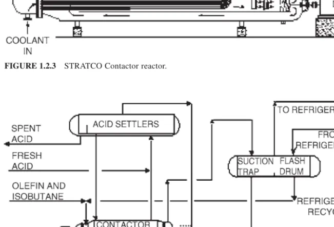
At the “heart” of STRATCO’s effluent refrigerated alkylation technology is the Contactor reactor (Fig. 1.2.3). The Contactor reactor is a horizontal pressure vessel con-taining an inner circulation tube, a tube bundle to remove the heat of reaction, and a mix-ing impeller. The hydrocarbon feed and sulfuric acid enter on the suction side of the impeller inside the circulation tube. As the feeds pass across the impeller, an emulsion of hydrocarbon and acid is formed. The emulsion in the Contactor reactor is continuously cir-culated at very high rates.
The superior mixing and high internal circulation of the Contactor reactor minimize the temperature difference between any two points in the reaction zone to within 1°F (0.6°C). This reduces the possibility of localized hot spots that lead to degraded alkylate product and increased chances for corrosion. The intense mixing in the Contactor reactor also pro-vides uniform distribution of the hydrocarbons in the acid emulsion. This prevents local-ized areas of nonoptimum isobutane/olefin ratios and acid/olefin ratios, both of which promote olefin polymerization reactions.
Figure 1.2.4 shows the typical Contactor reactor and acid settler arrangement. A por-tion of the emulsion in the Contactor reactor, which is approximately 50 LV % acid and 50 LV % hydrocarbon, is withdrawn from the discharge side of the impeller and flows to the acid settler. The hydrocarbon phase (reactor effluent) is separated from the acid emul-sion in the acid settlers. The acid, being the heavier of the two phases, settles to the lower portion of the vessel. It is returned to the suction side of the impeller in the form of an emulsion, which is richer in acid than the emulsion entering the settlers.
The STRATCO alkylation process utilizes an effluent refrigeration system to remove the heat of reaction and to control the reaction temperature. With effluent refrigeration, the hydrocarbons in contact with the sulfuric acid catalyst are maintained in the liquid phase. The hydrocarbon effluent flows from the top of the acid settler to the tube bundle in the
FIGURE 1.2.2 Feed mixing and cooling.
Contactor reactor. A control valve located in this line maintains a back pressure of about 60 lb/in2gage (4.2 kg/cm2gage) in the acid settler.
This pressure is adequate to prevent vaporization in the reaction system. In plants with multiple Contactor reactors, the acid settler pressures are operated about 5 lb/in2 (0.4 kg/cm2) apart to provide adequate pressure differential for series acid flow.
The pressure of the hydrocarbon stream from the top of the acid settler is reduced to about 5 lb/in2gage (0.4 kg/cm2gage) across the back pressure control valve. A portion of the effluent stream is flashed, reducing the temperature to about 35°F (1.7°C). Additional vaporization occurs in the Contactor reactor tube bundle as the net effluent stream removes the heat of reaction. The two-phase net effluent stream flows to the suction trap/flash drum where the vapor and liquid phases are separated.
1.14 ALKYLATION AND POLYMERIZATION
FIGURE 1.2.3 STRATCO Contactor reactor.
FIGURE 1.2.4 Contactor reactor/acid settler arrangement.
The suction trap/flash drum is a two-compartment vessel with a common vapor space. The net effluent pump transfers the liquid from the suction trap side (net effluent) to the effluent treating section via the feed/effluent exchangers. Refrigerant from the refrigera-tion secrefrigera-tion flows to the flash drum side of the sucrefrigera-tion trap/flash drum. The combined vapor stream is sent to the refrigeration section.
The sulfuric acid present in the reaction zone serves as a catalyst to the alkylation reac-tion. Theoretically, a catalyst promotes a chemical reaction without being changed as a result of that reaction. In reality, however, the acid is diluted as a result of the side reac-tions and feed contaminants. To maintain the desired spent acid strength, a small amount of fresh acid is continuously charged to the acid recycle line from the acid settler to the Contactor reactor, and a similar amount of spent acid is withdrawn from the acid settler.
In multiple-Contactor reactor plants, the reactors are usually operated in parallel on hydrocarbon and in series/parallel on acid, up to a maximum of four stages. Fresh acid and intermediate acid flow rates between the Contactor reactors control the spent acid strength. The spent acid strength is generally monitored by titration, which is done in the labo-ratory. In response to our customer requests, STRATCO has developed an on-line acid ana-lyzer that enables the operators to spend the sulfuric acid to lower strengths with much greater accuracy and confidence.
When alkylating segregated olefin feeds, the optimum acid settler configuration will depend on the olefins processed and the relative rates of each feed. Generally, STRATCO recommends processing the propylene at high acid strength, butylenes at intermediate strength, and amylenes at low strength. The optimum configuration for a particular unit may involve operating some reaction zones in parallel and then cascading to additional reaction zones in series. STRATCO considers several acid staging configurations for every design in order to provide the optimum configuration for the particular feed.
Refrigeration Section
Figure 1.2.5 is a diagram of the most common refrigeration configuration. The partially vaporized net effluent stream from the Contactor reactor flows to the suction trap/flash drum, where the vapor and liquid phases are separated. The vapor from the suction trap/flash drum is compressed by a motor or turbine-driven compressor and then con-densed in a total condenser.
A portion of the refrigerant condensate is purged or sent to a depropanizer. The remain-ing refrigerant is flashed across a control valve and sent to the economizer. If a depropaniz-er is included in the design, the bottoms stream from the towdepropaniz-er is also sent to the economizer. The economizer operates at a pressure between the condensing pressure and the compressor suction pressure. The economizer liquid is flashed and sent to the flash drum side of the suction trap/flash drum.
A lower-capital-cost alternative would be to eliminate the economizer at a cost of about 7 percent higher compressor energy. Another alternative is to incorporate a partial con-denser to the economizer configuration and thus effectively separate the refrigerant from the light ends, allowing for propane enrichment of the depropanizer feed stream. As a result, both depropanizer capital and operating costs can be reduced. The partial condens-er design is most cost-effective when feed streams to the alkylation unit are high (typical-ly greater than 40 LV %) in propane/propylene content.
For all the refrigeration configurations, the purge from the refrigeration loop is treated to remove impurities prior to flowing to the depropanizer or leaving the unit. These impu-rities can cause corrosion in downstream equipment. The main impurity removed from the purge stream is sulfur dioxide (SO2). SO2is produced from oxidation reactions in the reac-tion secreac-tion and decomposireac-tion of sulfur-bearing contaminants in the unit feeds.
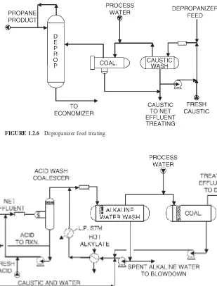
The purge is contacted with strong caustic (10 to 12 wt %) in an in-line static mixer and is sent to the caustic wash drum. The separated hydrocarbon stream from the caustic wash drum then mixes with process water and is sent to a coalescer (Fig. 1.2.6). The coalescer reduces the carryover caustic in the hydrocarbon stream that could cause stress corrosion cracking or caustic salt plugging and fouling in downstream equipment. The injection of process water upstream of the coalescer enhances the removal of caustic carryover in the coalescer.
Effluent Treating Section
The net effluent stream from the reaction section contains traces of free acid, alkyl sulfates, and dialkyl sulfates formed by the reaction of sulfuric acid with olefins. These alkyl sul-fates are commonly referred to as esters.Alkyl sulfates are reaction intermediates found in all sulfuric acid alkylation units, regardless of the technology. If the alkyl sulfates are not removed, they can cause corrosion and fouling in downstream equipment.
STRATCO’s net effluent treating section design has been modified over the years in an effort to provide more effective, lower-cost treatment of the net effluent stream. STRATCO’s older designs included caustic and water washes in series. Until recently, STRATCO’s standard design included an acid wash with an electrostatic precipitator fol-lowed by an alkaline water wash. Now STRATCO alkylation units are designed with an acid wash coalescer, alkaline water wash, and a water wash coalescer in series (Fig. 1.2.7) or with an acid wash coalescer followed by bauxite treating. Although all these treatment methods remove the trace amounts of free acid and reaction intermediates (alkyl sulfates) from the net effluent stream, the acid wash coalescer/alkaline water wash/water wash coa-lescer design and acid wash coacoa-lescer/bauxite treater design are the most efficient.
Fractionation Section
The fractionation section configuration of grassroots alkylation units, either effluent refrig-erated or autorefrigrefrig-erated, is determined by feed composition to the unit and product spec-ifications. As mentioned previously, the alkylation reactions are enhanced by an excess
1.16 ALKYLATION AND POLYMERIZATION
FIGURE 1.2.5 Refrigeration with economizer.
amount of isobutane. A large recycle stream is required to produce the optimum I/O volu-metric ratio of 7 : 1 to 10 : 1 in the feed to the Contactor reactors. Therefore, the fraction-ation section of the alkylfraction-ation unit is not simply a product separfraction-ation section; it also provides a recycle isobutane stream.
To meet overall gasoline pool RVP requirements, many of the recent alkylation designs require an alkylate RVP of 4 to 6 lb/in2(0.28 to 0.42 kg/cm2). To reduce the RVP of the alkylate, a large portion of the n-butane and isopentane must be removed. Low C5⫹ con-tent of the n-butane product is difficult to meet with a vapor side draw on the DIB and STRATCO EFFLUENT REFRIGERATED H2SO4ALKYLATION PROCESS 1.17
FIGURE 1.2.6 Depropanizer feed treating.
FIGURE 1.2.7 Effluent treating section.
requires the installation of a debutanizer tower (Fig. 1.2.8). Typically, a debutanizer is required when the specified C5⫹content of the n-butane product must be less than 2 LV %. A simpler system consisting of a deisobutanizer (DIB) with a side draw may suffice if a high-purity n-butane product is not required. The simplest fractionation system applies to a unit processing a high-purity olefin stream, such as an isobutane/isobutylene stream from a dehydrogenation unit. For these cases, a single isostripper can be used to produce a recycle isobutane stream, a low-RVP alkylate product, and a small isopentane product. An isostripper requires no reflux and many fewer trays than a DIB.
Blowdown Section
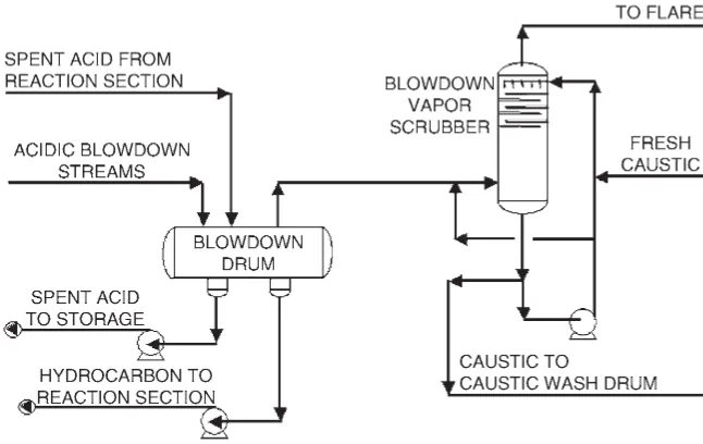
The acidic blowdown vapors from potential pressure relief valve releases are routed to the acid blowdown drum to knock out any entrained liquid sulfuric acid. Additionally, spent acid from the last Contactor reactor/acid settler system(s) in series is sent to the acid blowdown drum. This allows any residual hydrocarbon in the spent acid to flash. The acid blowdown drum also provides surge capacity for spent acid. The acidic vapor effluent from the acid blowdown drum is sent to the blowdown vapor scrubber. The acidic vapors are countercur-rently contacted with a circulating 12 wt % caustic solution in a six-tray scrubber (Fig. 1.2.9).
TECHNOLOGY IMPROVEMENTS
The following information is provided to highlight important design information about the STRATCO H2SO4effluent refrigerated alkylation process.
STRATCO Contactor Reactor
The alkylation reaction requires that the olefin be contacted with the acid catalyst concur-rently with a large excess of isobutane. If these conditions are not present, polymerization
1.18 ALKYLATION AND POLYMERIZATION
FIGURE 1.2.8 Fractionation system.
reactions will be promoted which result in a heavy, low-octane product and high acid con-sumption.
Since the early days of alkylation, the Contactor reactor has been recognized as the superior alkylation reactor with higher product quality and lower acid consumption than those of competitive designs. However, STRATCO continues to modify and improve the Contactor reactor to further optimize the desirable alkylation reaction. Several of these improvements are listed next.
The modern Contactor reactor has an eccentric shell as opposed to a concentric shell in older models. The eccentric shell design provides superior mixing of the acid and hydro-carbons and eliminates any localized “dead” zones where polymerization reactions can occur. The result is improved product quality and substantially lower acid consumption.
The heat exchange bundle in the Contactor reactor has been modified to improve the flow path of the acid/hydrocarbon mixture around the tubes. Since this results in improved heat transfer, the temperature gradient across the reaction zone is quite small. This results in optimal reaction conditions.
The heat exchange area per Contactor reactor has been increased by more than 15 per-cent compared to that in older models. This has resulted in an increased capacity per Contactor reactor and also contributes to continual optimization of the reaction conditions. The design of the internal feed distributor has been modified to ensure concurrent con-tact of the acid catalyst and olefin/isobutane mixture at the point of initial concon-tact.
The Contactor reactor hydraulic head has been modified to include a modern, cartridge-type mechanical seal system. This results in a reliable, easy-to-maintain, and long-lasting seal system.
STRATCO offers two types of mechanical seals: a single mechanical seal with a Teflon sleeve bearing and a double mechanical seal with ball bearings that operates with a barri-er fluid. The STRATCO Contactor reactors can be taken off-line individually if any main-tenance is required. If seal replacement is required during normal operation, the Contactor reactor can be isolated, repaired, and back in service in less than 24 h.
STRATCO EFFLUENT REFRIGERATED H2SO4ALKYLATION PROCESS 1.19
FIGURE 1.2.9 Blowdown system.
Process Improvements
Several process modifications have been made to provide better alkylation reaction condi-tions and improve overall unit operacondi-tions. Some of these modificacondi-tions are as follows:
Acid retention time in the acid settler has been reduced by employing coalescing media in the acid settler. The reduced retention time minimizes the potential for undesirable poly-merization reactions in the acid settler. Two stages of coalescing are employed to separate the hydrocarbon product from the acid phase. The first stage results in a 90 vol % H2SO4 stream that is recycled to the Contactor reactor. The second stage reduces the acid carry-over rate to only 10 to 15 vol ppm. This is at least a threefold decrease in comparison to simple gravity settling with a typical 50 to 100 vol ppm in the hydrocarbon stream.
Fresh H2SO4is continuously added to the unit, and spent H2SO4is continuously with-drawn. In multiple-Contactor reactor units, the H2SO4flows in series between the Contactor reactors. Thus, the acid strength across the unit is held at its most effective value, and the acid strength at any one location in the unit does not vary with time. This method of han-dling H2SO4provides a very stable operation and continual acid strength optimization.
To ensure complete and intimate mixing of the olefin and isobutane feeds before con-tacting with the acid catalyst, these hydrocarbon feeds are premixed outside the Contactor reactor and introduced as one homogeneous stream.
Alkyl sulfates are removed in a fresh acid wash coalescer/warm alkaline water wash. Afterward, the net effluent stream is washed with fresh process water to remove traces of caustic, then is run through a coalescer to remove free water before being fed to the DIB tower. This system is superior to the caustic wash/water wash system which was imple-mented in older designs.
The fractionation system can be designed to accommodate makeup isobutane of any purity, eliminating the need for upstream fractionation of the makeup isobutane.
The alkylation unit is designed to take maximum advantage of the refinery’s steam and utility economics. Depending upon these economics, the refrigeration compressor and/or Contactor reactors can be driven with steam turbines (condensing or noncondensing) or electric motors, to minimize unit operating costs.
STRATCO now employs a cascading caustic system in order to minimize the volume and strength of the waste caustic (NaOH) stream from the alkylation unit. In this system, fresh caustic is added to the blowdown vapor scrubber, from which it is cascaded to the depropanizer feed caustic wash and then to the alkaline water wash. The only waste stream from the alkylation unit containing caustic is the spent alkaline water stream. The spent alkaline water stream has a very low concentration of NaOH (⬍0.05 wt %) and is com-pletely neutralized in the neutralization system before being released to the refinery waste-water treatment facility. Since the cascading system maintains a continuous caustic makeup flow, it has the additional advantages of reduced monitoring requirements and reduced chance of poor treating due to inadequate caustic strength.
H
2
SO
4ALKYLATION PROCESS COMPARISON
The most important variables that affect product quality in a sulfuric acid alkylation unit are temperature, mixing, space velocity, acid strength, and concentration of isobutane feed in the reactor(s). It is usually possible to trade one operating variable for another, so there is often more than one way to design a new plant to meet octane requirements with a giv-en olefin feed.
Going beyond the customary alkylation process variables, STRATCO has developed unique and patented expertise in separate processing of different olefin feeds. This
tech-1.20 ALKYLATION AND POLYMERIZATION
nology can improve product quality compared to alkylation of the same olefins mixed together.
The two major H2SO4 alkylation processes are the STRATCO effluent refrigerated process and the autorefrigerated process by design; these two processes take different approaches to achieve product quality requirements. These design differences and their impacts on operability and reliability are discussed below.
Cooling and Temperature Control
The STRATCO effluent refrigerated process utilizes a liquid-full reactor/acid settler sys-tem. The heat of reaction is removed by an internal tube bundle. In the autorefrigerated process, the heat of reaction is removed by operating the reactor at a pressure where the acid/hydrocarbon mixture boils. The autorefrigerated reactor and acid settler therefore contain a vapor phase above the two mixed liquid phases. Both systems can be operated in the same temperature range. However, the STRATCO system is much easier to operate.
Temperature control in the STRATCO effluent refrigerated process is simpler than that in the autorefrigerated process. The pressure of the refrigerant flash drum is used to con-trol the operating temperature of all the Contactor reactors in the reaction zone. The autorefrigerated process requires two or more pressure zones per reactor to control tem-perature and to maintain liquid flow between the reactor zones.
Good control of the acid/hydrocarbon ratio in a sulfuric acid alkylation reactor is crit-ical to reactor performance. This is the area in which the STRATCO system has its largest operability advantage. Since the Contactor reactor system operates liquid-full, gravity flow is used between the Contactor reactor and acid settler. The Contactor/settler system is hydraulically designed to maintain the optimum acid-to-hydrocarbon ratio in the reactor as long as the acid level in the acid settler is controlled in the correct range. The acid/hydro-carbon ratio in the Contactor reactor can be easily verified by direct measurement. In con-trast, the autorefrigerated process requires manipulation of an external acid recycle stream in order to control the acid/hydrocarbon ratio in the reactor. As a result, the acid/hydro-carbon ratio in the different mixing zones varies and cannot be readily measured.
The Contactor reactor/settler system is also designed to minimize acid inventory in the acid settler. Minimizing the unmixed acid inventory suppresses undesirable side reactions which degrade product quality and increase acid consumption. Quick, clean separation of the acid and hydrocarbon phases is much more difficult in the boiling autorefrigerated process.
When operated at the same temperature, the effluent refrigerated system requires some-what greater refrigeration compressor horsepower than the autorefrigerated process because of resistance to heat transfer across the tube bundle.
Mixing
The topic of mixing in a sulfuric acid alkylation unit encompasses (1) the mixing of the isobutane and olefin feeds outside the reactor, (2) the method of feed injection, and (3) the mixing intensity inside the reactor. The best-quality alkylate is produced with the lowest acid consumption when
● The “local” isobutene/olefin ratio in the mixing zone is maximized by premixing the olefin and isobutane feeds.
● The feed is rapidly dispersed into the acid/hydrocarbon emulsion.
● Intense mixing gives the emulsion a high interfacial area.
In STRATCO’s effluent refrigerated process, all the isobutane sent to the reactors is pre-mixed with olefin feed, maximizing the “local” isobutane concentration at the feed point. The feed mixture is rapidly dispersed into the acid catalyst via a special injection nozzle. Mixing occurs as the acid/hydrocarbon emulsion passes through the hydraulic head impeller and as it circulates through the tube bundle.
The tube bundle in the Contactor reactor is an integral part of the mixing system. The superior mixing in the Contactor reactor produces an emulsion with a high interfacial area, even heat dissipation, and uniform distribution of the hydrocarbons in the acid. Intense mix-ing reduces the temperature gradient within the Contactor’s 11,500-gal volume to less than 1°F. The result is suppression of olefin polymerization reactions in favor of the alkylation reaction. Good mixing is particularly important when the olefin feed contains propylene.
In the autorefrigerated process, only a portion of the isobutane is premixed with the olefin feed. The “local” concentration of isobutane is therefore lower when the feeds first make contact with acid catalyst. The less intensive mixing in the autorefrigerated process can result in nonuniform distribution of the hydrocarbons in the acid. The desired finely dispersed hydrocarbon in acid emulsion cannot be easily controlled throughout the different reaction zones. As a consequence, the autorefrigerated alkylation process must be operated at a very low space velocity and temperature to make up for its disadvantage in mixing.
Acid Strength
The acid cascade system employed by STRATCO provides a higher average acid strength in the reaction zone than can usually be accomplished with large autorefrigerated reactors. The higher average acid strength results in higher alkylate octane with reduced acid consumption. STRATCO has recently completed pilot-plant studies that enable us to optimize the acid cas-cade system for different plant capacities. Large autorefrigerated reactors must be designed for lower space velocity and/or lower operating temperature to compensate for this difference.
Isobutane Concentration and Residence Time in the Reactor
Since the Contactor reactor is operated liquid-full, all the isobutane fed to the reactor is available for reaction. In the autorefrigerated process, a portion of the isobutane fed to the reactor is vaporized to provide the necessary refrigeration. The isobutane is also diluted by reaction products as it cascades through the reactor. To match the liquid-phase isobutane concentration in the STRATCO process, the deisobutanizer recycle rate and/or purity in the autorefrigerated process must be increased to compensate for the dilution and isobu-tane flashed. The DIB operating costs will therefore be higher for the autorefrigerated process unless other variables such as space velocity or temperature are used to compen-sate for a lower isobutane concentration.
Research studies have shown that trimethylpentanes, the alkylate components which have the highest octane, are degraded by extended contact with acid. It is therefore desir-able to remove alkylate product from the reactor as soon as it is produced. STRATCO Contactor reactors operate in parallel for the hydrocarbons and approach this ideal more closely than the series operation of reaction zones in autorefrigerated reactors.
Reliability
One of the primary factors affecting the reliability of an alkylation unit is the number and type of mechanical seals required in the reaction zone.
1.22 ALKYLATION AND POLYMERIZATION
Each Contactor reactor has one mechanical seal. STRATCO offers two types of mechanical seals; a single mechanical seal with a Teflon sleeve bearing and a double mechanical seal with ball bearings that operates with a barrier fluid. The Contactor reac-tors can be taken off-line individually if any maintenance is required. If seal replacement is required during normal operation, the Contactor reactor can be isolated, repaired, and back in service in less than 24 h.
The number of mechanical seals required for autorefrigerated reactor systems is high-er. An agitator for every reactor compartment and redundant acid recycle pumps are required. The dry running seals often used on autorefrigerated reactor agitators have a shorter expected life than STRATCO’s double mechanical seal. While special agitators are available which allow mechanical seals to be replaced without shutting down the reactor, many refiners’ safety procedures require the autorefrigerated reactor to be shut down for this type of maintenance. It is common practice to shut down the agitator and stop feed to a reactor chamber in the event of agitator seal or shaft problems. Product quality will then be degraded until the reactor can be shut down for repairs.
Separate Processing of Different Olefin Feeds
Olefin feed composition is not normally an independent variable in an alkylation unit. STRATCO has recently developed unique and patented expertise in the design of alkyla-tion units which keep different olefin feeds separate and alkylate them in separate reactors. By employing this technology, each olefin can be alkylated at its optimum conditions while avoiding the “negative synergy” which occurs when certain olefins are alkylated together. This know-how provides an advantage with mixtures of propylene, butylene, and amylene, and with mixtures of iso- and normal olefins. As a result, alkylate product qual-ity requirements can be met at more economical reaction conditions.
COMMERCIAL DATA
STRATCO alkylation technology is responsible for about 35 percent of the worldwide production of alkylate and about 74 percent of sulfuric acid alkylation production. Of the 276,000 bbl/day of alkylation capacity added from 1991 to 2001, about 81 percent is STRATCO technology.
Capital and Utility Estimates
Total estimated inside battery limit (ISBL) costs for grassroots STRATCO effluent refrig-erated alkylation units are shown in Table 1.2.1.
Utility and chemical consumption for an alkylation unit can vary widely according to feed composition, product specifications, and design alternatives. The values in Table 1.2.2 are averages of many designs over the last several years and reflect mainly butylene feeds with water cooling and electrical drivers for the compressor and Contactor reactors. Steam and cooling water usage has crept up in recent years as a result of lower RVP targets for the alkylate product. The acid consumption given in the table does not include the con-sumption due to feed contaminants.
More information on alkylate properties and STRATCO’s H2SO4effluent refrigerated alkylation process is available at www.stratco.dupont.com.
REFERENCES
1. D. C. Graves, K. E. Kranz, D. M. Buckler, and J. R. Peterson, “Alkylation Best Practices for the New Millennium,” NPRA Annual Meeting in Baton Rouge, La., 2001.
2. D. C. Graves, “Alkylation Options for Isobutylene and Isopentane,” ACS meeting, 2001. 3. J. R. Peterson, D. C. Graves, K. E. Kranz, and D. M. Buckler, “Improved Amylene Alkylation
Economics,” NPRA Annual Meeting, 1999.
4. K. E. Kranz and D. C. Graves, “Olefin Interactions in Sulfuric Acid Catalyzed Alkylation,” Arthur Goldsby Symposium, Division of Petroleum Chemistry, 215th National Meeting of the American Chemical Society (ACS), Dallas, Tex., 1998.
5. D. C. Graves, K. E. Kranz, J. K. Millard, and L. F. Albright,Alkylation by Controlling Olefin Ratios. Patent 5,841,014, issued 11/98.
6. D. C. Graves, K. E. Kranz, J. K. Millard, and L. F. Albright,Alkylation by Controlling Olegin Ratios. Patent 6,194,625, issued 2/01.
1.24 ALKYLATION AND POLYMERIZATION
TABLE 1.2.1 Estimated Erected Costs (U.S., ±30%)
Mid-1999 U.S. Gulf Coast basis Production Total erected costs, capacity, BPD $/bbl
5,000 5,000
12,000 4,500
20,000 4,000
TABLE 1.2.2 Estimated Utilities and Chemicals (per Barrel of Alkylate Production)
Electric power, kW 15
Cooling water, gal 1370
Process water, gal 4
Steam, lb 194
Fresh acid, lb 13
NaOH, lb 0.05
CHAPTER 1.3
UOP ALKYLENE™ PROCESS
FOR MOTOR
FUEL ALKYLATION
Cara Roeseler
UOP LLC Des Plaines, IllinoisINTRODUCTION
The UOP Alkylene process is a competitive and commercially available alternative to liq-uid acid technologies for alkylation of light olefins and isobutane. Alkylate is a key blend-ing component for gasoline havblend-ing high octane, low Reid vapor pressure (RVP), low sulfur, and low volatility. It is composed of primarily highly branched paraffinic hydro-carbons. Changing gasoline specifications in response to legislation will increase the importance of alkylate, making it an ideal “clean fuels” blend stock. Existing liquid acid technologies, while well proven and reliable, are increasingly under political and regula-tory pressure to reduce environmental and safety risks through increased monitoring and risk mitigation. A competitive solid catalyst alkylation technology, such as the Alkylene process, would be an attractive alternative to liquid acid technologies.
UOP developed the Alkylene process during the late 1990s, in response to the indus-try’s need for an alternative to liquid acid technologies. Early attempts with solid acid cat-alysts found some to have good alkylation properties, but the catcat-alysts also had short life, on the order of hours. In addition, these materials could not be regenerated easily, requir-ing a carbon burn step. Catalysts with acid incorporated on a porous support had been investigated but not commercialized. UOP invented the novel HAL-100 catalyst that has high alkylation activity and long catalyst stability and easily regenerates without a high-temperature carbon burn. Selectivity of the HAL-100 is excellent, and product quality is comparable to that of the product obtained from liquid acid technologies.
ALKYLENE PROCESS
Olefins react with isobutane on the surface of the HAL-100 catalyst to form a complex mixture of isoalkanes called alkylate. The major constituents of alkylate are highly branched trimethylpentanes (TMP) that have high-octane blend values of approximately
1.25
100. Dimethyl hexanes (DMH) have lower-octane blend values and are present in alkylate at varying levels.
Alkylation proceeds via a carbenium ion mechanism, as shown in Fig. 1.3.1. The com-plex reaction paths include an initiation step, a propagation step, and hydrogen transfer. Secondary reactions include polymerization, isomerization, and cracking to produce other isoalkanes including those with carbon numbers which are not multiples of 4. The primary reaction products are formed via simple addition of isobutane to an olefin such as propy-lene, butenes, and amylenes. The key reaction step is the protonation of a light olefin on the solid catalyst surface followed by alkylation of an olefin on the C4carbocation, form-ing the C8carbocation. Hydride transfer from another isobutane molecule forms the C8 paraffin product. Secondary reactions result in less desirable products, both lighter and heavier than the high-octane C8 products. Polymerization to acid-soluble oil (ASO) is found in liquid acid technologies and results in additional catalyst consumption and yield loss. The Alkylene process does not produce acid-soluble oil. The Alkylene process also has minimal polymerization, and the alkylate has lighter distillation properties than alky-late from HF or H2SO4liquid acid technologies.
Alkylation conditions that favor the desired high-octane trimethylpentane include low process temperature, high localized isobutane/olefin ratios, and short contact time between the reactant and catalyst. The Alkylene process is designed to promote quick, intimate con-tact of short duration between hydrocarbon and catalyst for octane product, high yield, and efficient separation of alkylate from the catalyst to minimize undesirable secondary reac-tions. Alkylate produced from the Alkylene process is comparable to alkylate produced from traditional liquid acid technologies without the production of heavy acid-soluble oil. The catalyst is similar to other hydroprocessing and conversion catalysts used in a typical refinery. Process conditions are mild and do not require expensive or exotic metallurgy.
1.26 ALKYLATION AND POLYMERIZATION
UOP ALKYLENE™ PROCESS FOR MOTOR FUEL ALKYLATION 1.27
Reactor temperature, isobutene/olefin ratio, contact time, and catalyst/olefin ratios are the key operating parameters.
Feeds to the Alkylene unit are dried and treated to move impurities and contaminants such as diolefins, oxygenates, nitrogen, and sulfur. These contaminants also cause higher acid consumption, higher acid-soluble oil formation, and lower acid strength in liquid acid technologies. Diolefin saturation technology, such as the Huels Selective Hydrogenation Process technology licensed by UOP LLC, saturates diolefins to the corresponding monoolefin and isomerizes the 1-butene to 2-butene. The alkylate formed by alkylating isobutane with 2-butene is the preferred 2,2,3-TMP compared to the 2,2-DMH formed by alkylating isobutane with 1-butene.
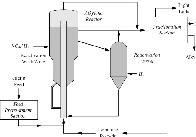
The olefin and isobutane (Fig. 1.3.2) are combined and injected into a carbon-steel ris-er reactor with continuous catalyst reactivation (Fig. 1.3.3) to maintain a constant catalyst activity and minimize catalyst inventory. This provides constant product quality, high yield, and high on-stream efficiency. Liquid-phase hydrocarbon reactants transport the cat-alyst around the reactor circuit where velocities are low relative to those of other moving catalyst processes. The reaction time is on the order of minutes for the completion of the primary reactions and to minimize secondary reactions. The catalyst and hydrocarbon are intimately mixed during the reaction, and the catalyst is easily disengaged from the carbon product at the top of the reactor. The catalyst is reactivated by a simple hydro-genation of the heavier alkylate on the catalyst in the reactivation wash zone. Hydrogen consumption is minimal as the quantity of heavy alkylate on the HAL-100 catalyst is very small. The reactivation process is highly effective, restoring the activity of the catalyst to nearly 100 percent of fresh. The liquid-phase operation of the Alkylene process results in less abrasion than in other catalyst circulation processes due to the lubricating effect of the liquid. Furthermore, the catalyst and hydrocarbon velocities are low relative to those in other moving catalyst processes. This minimizes the catalyst replacement requirements. Catalyst circulation is maintained to target catalyst/olefin ratios. A small catalyst slip-stream flows into a separate vessel for reactivation in vapor phase with relatively mild con-ditions to remove any last traces of heavy material and return the catalyst activity to essentially the activity of fresh catalyst.
Alkylate from the reactor is sent to a downstream fractionation section, which is simi-lar to fractionation sections in liquid acid process flow schemes. The fractionation section recycles the unconverted isobutane back to the reactor and separates out the final alkylate product.
FIGURE 1.3.2 Alkylene process flow scheme.
ALKYLENE PERFORMANCE
HAL-100, the Alkylene process catalyst, has high acidity to promote desirable alkylation reactions. It has optimum particle size and pore distribution to allow for good mass transfer of reactants and products into and out of the catalyst. The catalyst has been commercially produced and demonstrates high physical strength and very low attrition rates in extensive physical testing. Catalyst attrition rates are several orders of magnitude lower than those experienced in other moving-bed regeneration processes in the refining industry.
HAL-100 has been demonstrated in a stability test of 9 months with full isobutane recy-cle and showed excellent alkylate product qualities as well as catalyst stability. Performance responses to process parameters such as isobutane/olefin ratio, catalyst/olefin ratio, and process temperature were measured. Optimization for high performance, cata-lyst stability, and economic impact results in a process technology competitive with tradi-tional liquid acid technologies (Fig. 1.3.4).
Typical light olefin feedstock compositions including propylene, butylenes, and amylenes were also studied. The primary temporary deactivation mechanism is the block-age of the active sites by heavy hydrocarbons. These heavy hydrocarbons are significant-ly lower in molecular weight than acid-soluble oil that is typical of liquid acid technologies. These heavy hydrocarbons are easily removed by contacting the catalyst with hydrogen and isobutane to strip them from the catalyst surface. These heavy hydro-carbons are combined in the total alkylate product pool and are accounted for in the alky-late properties from the Alkylene process.
The buildup of heavy hydrocarbons on the catalyst surface is a function of the operat-ing severity and the feedstock composition. The reactivation conditions and the frequency of vapor reactivation are optimized in order to achieve good catalyst stability as well as commercially economical conditions.
FIGURE 1.3.3 Alkylene process flow diagram.
ENGINEERING DESIGN AND OPTIMIZATION
The liquid transport reactor for the Alkylene process was developed by UOP based on extensive UOP experience in fluid catalytic cracking (FCC) and continuous catalyst regen-eration (CCR) technologies. Novel engineering design concepts were incorporated. Extensive physical modeling and computational fluid dynamics modeling were used to verify key engineering design details. More than 32 patents have been issued for the Alkylene process technology.
The reactor is designed to ensure excellent mixing of catalyst and hydrocarbon with lit-tle axial dispersion as the mixture moves up the riser. This ensures sufficient contact time and reaction time for alkylation. Olefin injection nozzles have been engineered to mini-mize high olefin concentration at the feed inlet to the riser. The catalyst is quickly sepa-rated from the hydrocarbon at the top of the riser and falls by gravity into the reactivation zone. The catalyst settles into a packed bed that flows slowly downward in the upper sec-tion of the vessel, where it is contacted with low-temperature hydrogen saturated isobutane recycle. The heavy hydrocarbons are hydrogenated and desorbed from the catalyst. The reactivated catalyst flows down standpipes and back into the bottom of the riser. The reac-tor section includes separate vessels for reactivating a slipstream of catalyst at a higher temperature to completely remove trace amounts of heavy hydrocarbons. By returning freshly reactivated catalyst to the riser continuously, catalyst activity is maintained for con-sistent performance.
The UOP Butamer process catalytically converts normal butane to isobutane with high selectivity, minimum hydrogen consumption, and excellent catalyst stability. When the Butamer process is combined with the Alkylene process,n-butane in the feed can be react-ed to extinction, thereby rreact-educing the fresh fereact-ed saturate requirements. In addition, the UOP ALKYLENE™ PROCESS FOR MOTOR FUEL ALKYLATION 1.29
C5
FIGURE 1.3.4 Catalyst comparison: mixed 4 olefin feed.
increased isobutane concentration in the isostripper reduces the size of the isostripper and allows for a reduction in utilities consumption. A novel flow scheme for the optimal inte-gration of the Butamer process into the Alkylene process was developed. The two units can share common fractionation and feed pretreatment equipment. Synergy of the two units reduces the capital cost requirement for the addition of the Butamer process and reduces the operating cost. Table 1.3.1 illustrates the maximum utilization of the makeup C4 paraf-fin stream and the utilities savings.
ALKYLENE PROCESS ECONOMICS
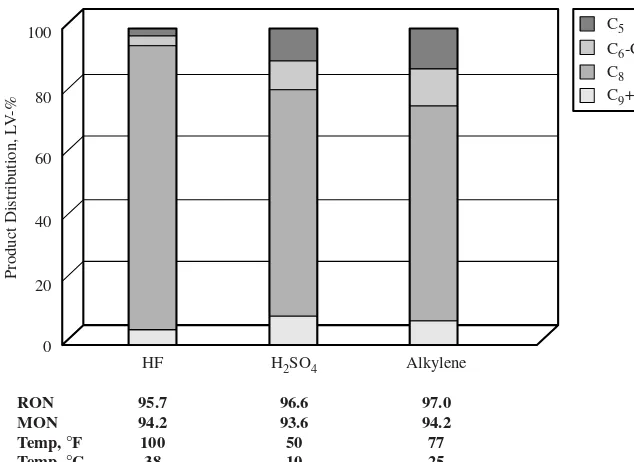
The product research octane number can be varied according to the reaction temperature and the isobutane/olefin ratio. Additional refrigeration duty can be justified by higher product octane, depending on the needs of the individual refiner. Higher isobutane/olefin ratio requires higher capital and utilities. Mixed propylene and butylene feedstocks can also be processed with less dependence on operating temperature. However, the alkylate product octane is typically lower from mixed propylene and butylene feed than from buty-lene-only feed. Processing some amylenes with the butylenes will result in slightly lower octane. Most refiners have blended the C5stream in the gasoline pool. However, with increasing restrictions on Reid vapor pressure, refiners are pulling C5out of the gasoline pool and processing some portion in alkylation units.
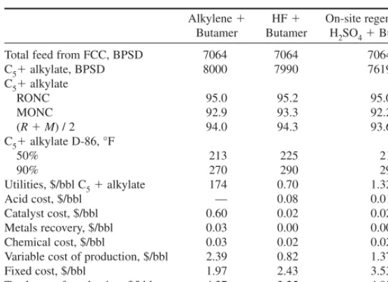
The three cases shown in Table 1.3.2 compare the economics of the Alkylene process with those of conventional liquid acid alkylation. The basis is 8000 BPSD of alkylate prod-uct from the Alkylene process. Case 1 is the Alkylene process, case 2 is an HF alkylation unit, and case 3 is a sulfuric acid unit with on-site acid regeneration. All cases include a Butamer process to maximize feed utilization.
The Alkylene process has a yield advantage over liquid acid alkylation technologies and does not produce acid-soluble oil (ASO) by-products. In addition, the capital cost of the Alkylene process is competitive compared with existing technologies, and maintenance costs are lower. The HF alkylation unit requires HF mitigation capital and operating costs. The sulfuric acid alkylation unit requires regeneration or transport of large volumes of acid. Overall, the Alkylene process is a safe and competitive option for today’s refiner.
SUMMARY
Future gasoline specifications will require refiners to maximize the use of assets and rebal-ance refinery gasoline pools. The potential phase-out of MTBE will create the need for
1.30 ALKYLATION AND POLYMERIZATION
TABLE 1.3.1 Alkyene Process Capital Costs
Alkylene Alkylene ⫹Butamer Total feed from FCC, BPSD 7064 7064
C4paraffin makeup 9194 2844
C5⫹alkylate, BPSD 8000 8000
C5⫹alkylate RONC 95.0 95.0
USGC EEC, million $ 43.0 43.7
Utilities Base 0.96*Base
clean, high-octane blending components, such as alkylate, to allow refiners to meet pool requirements without adding aromatics, olefins, or RVP. Alkylate from the Alkylene process has excellent alkylate properties equivalent to those of HF acid technology, does not generate ASO, has better alkylate yield, and is a safe alternative to liquid acid tech-nologies. Recent developments propel the Alkylene process technology into the market-place as a viable option with technical and economic benefits.
As the demand for alkylate continues to grow, new alkylation units will help refiners meet the volume and octane requirements of their gasoline pools. The Alkylene process was developed as a safe alternative to commercial liquid acid alkylation technologies.
BIBLIOGRAPHY
Cara M. Roeseler, Steve M. Black, Dale J. Shields, and Chris D. Gosling, “Improved Solid Catalyst Alkylation Technology for Clean Fuels: The Alkylene Process,” NPRA Annual Meeting, San Antonio, March 2002.
UOP ALKYLENE™ PROCESS FOR MOTOR FUEL ALKYLATION 1.31
TABLE 1.3.2 Comparison of Alkylation Options
Alkylene ⫹ HF⫹ On-site regeneration Butamer Butamer H2SO4⫹Butamer
Total feed from FCC, BPSD 7064 7064 7064
C5⫹alkylate, BPSD 8000 7990 7619
C5⫹alkylate
RONC 95.0 95.2 95.0
MONC 92.9 93.3 92.2
(R⫹M) / 2 94.0 94.3 93.6
C5⫹alkylate D-86, °F
50% 213 225 21
90% 270 290 29
Utilities, $/bbl C5⫹alkylate 174 0.70 1.32
Acid cost, $/bbl — 0.08 0.01
Catalyst cost, $/bbl 0.60 0.02 0.02
Metals recovery, $/bbl 0.03 0.00 0.00
Chemical cost, $/bbl 0.03 0.02 0.02
Variable cost of production, $/bbl 2.39 0.82 1.37
Fixed cost, $/bbl 1.97 2.43 3.53
CHAPTER 1.4
UOP HF ALKYLATION
TECHNOLOGY
Kurt A. Detrick, James F. Himes,
Jill M. Meister, and Franz-Marcus Nowak
UOP Des Plaines, Ilinois
INTRODUCTION
The UOP* HF Alkylation process for motor fuel production catalytically combines light olefins, which are usually mixtures of propylene and butylenes, with isobutane to produce a branched-chain paraffinic fuel. The alkylation reaction takes place in the presence of hydrofluoric (HF) acid under conditions selected to maximize alkylate yield and quality. The alkylate product possesses excellent antiknock properties and high-octane because of its high content of highly branched paraffins. Alkylate is a clean-burning, sulfur, low-RVP gasoline blending component that does not contain olefinic or aromatic compounds. The HF Alkylation process was developed in the UOP laboratories during the late 1930s and early 1940s. The process was initially used for the production of high-octane aviation fuels from butylenes and isobutane. In the mid-1950s, the development and con-sumer acceptance of more-sophisticated high-performance automotive engines placed a burden on the petroleum refiner both to increase gasoline production and to improve motor fuel quality. The advent of catalytic reforming techniques, such as the UOP Platforming* process, provided an important tool for the production of high-quality gasolines available to refiners. However, the motor fuel produced in such operations is primarily aromatic-based and is characterized by high sensitivity (that is, the spread between research and motor octane numbers). Because automobile performance is more closely related to road octane rating (approximately the average of research and motor octanes), the production of gasoline components with low sensitivity was required. A natural consequence of these requirements was the expansion of alkylation operations. Refiners began to broaden the range of olefin feeds to both existing and new alkylation units to include propylene and occasionally amylenes as well as butylenes. By the early 1960s, the HF Alkylation process had virtually displaced motor fuel polymerization units for new installations, and refiners had begun to gradually phase out the operation of existing polymerization plants.
The importance of the HF Alkylation process in the refining situation of the 2000s has been increased even further by the scheduled phase-out of MTBE and the increased
1.33 *Trademark and/or service mark of UOP.
emphasis on low-sulfur gasoline. The contribution of the alkylation process is critical in the production of quality motor fuels including many of the “environmental” gasoline blends. The process provides refiners with a tool of unmatched economy and efficiency, one that will assist refiners in maintaining or strengthening their position in the production and marketing of gasolines.
PROCESS CHEMISTRY
General
In the HF Alkylation process, HF acid is the catalyst that promotes the isoparaffin-olefin reaction. In this process, only isoparaffins with tertiary carbon atoms, such as isobutane or isopentane, react with the olefins. In practice, only isobutane is used because isopentane has a high octane number and a vapor pressure that has historically allowed it to be blend-ed directly into finishblend-ed gasolines. However, where environmental regulations have reduced the allowable vapor pressure of gasoline, isopentane is being removed from gaso-line, and refiner interest in alkylating this material with light olefins, particularly propy-lene, is growing.
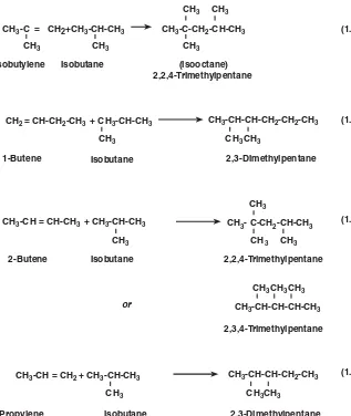
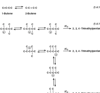
The actual reactions taking place in the alkylation reactor are many and are relatively complex. The equations in Fig. 1.4.1 illustrate the primary reaction products that may be expected for several pure olefins.
In practice, the primary product from a single olefin constitutes only a percentage of the alkylate because of the variety of concurrent reactions that are possible in the alkyla-tion environment. Composialkyla-tions of pilot-plant products produced at condialkyla-tions to maxi-mize octane from pure-olefin feedstocks are shown in Table 1.4.1.
Reaction Mechanism
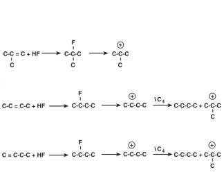
Alkylation is one of the classic examples of a reaction or reactions proceeding via the car-benium ion mechanism. These reactions include an initiation step and a propagation step and may include an isomerization step. In addition, polymerization and cracking steps may be involved. However, these side reactions are generally undesirable. Examples of these reactions are given in Fig. 1.4.2.
Initiation. The initiation step (Fig. 1.4.2a) generates the tertiary butyl cations that will subsequently carry on the alkylation reaction.
Propagation. Propagation reactions (Fig. 1.4.2b) involve the tertiary butyl cation reacting with an olefin to form a larger carbenium ion, which then abstracts a hydride from an isobutane molecule. The hydride abstraction generates the isoparaffin plus a new tertiary butyl cation to carry on the reaction chain.
Isomerization. Isomerization [Eq. (1.4.12), shown in Fig. 1.4.2c] is very important in producing good octane quality from a feed that is high in 1-butene. The isomerization of 1-butene is favored by thermodynamic equilibrium. Allowing 1-butene to isomerize to 2-butene reduces the production of dimethylhexanes (research octane number of 55 to 76) and increases the production of trimethylpentanes. Many recent HF Alkylation units, especially those processing only butylenes, have upstream olefin isomerization units that isomerize the 1-butene to 2-butene.
1.34 ALKYLATION AND POLYMERATION
UOP HF ALKYLATION TECHNOLOGY 1.35
Equation (1.4.13) is an example of the many possible steps involved in the isomeriza-tion of the larger carbenium ions.
Other Reactions. The polymerization reaction [Eq. (1.4.14), shown in Fig. 1.4.2d] results in the production of heavier paraffins, which are undesirable because they reduce alkylate octane and increase alkylate endpoint. Minimization of this reaction is achieved by proper choice of reaction conditions.
The larger polymer cations are susceptible to cracking or disproportionation reactions [Eq. (1.4.15)], which form fragments of various molecular weights. These fragments can then undergo further alkylation.
1.36 ALKYLATION AND POLYMERATION
TABLE 1.4.1 Compositions of Alkylate from Pure-Olefin Feedstocks
Olefin
Component, wt % C3H6 iC4H8 C4H8-2 C4H8-1
C5isopentane 1.0 0.5 0.3 1.0
C6s:
Dimethylbutanes 0.3 0.8 0.7 0.8
Methylpentanes — 0.2 0.2 0.3
C7s:
2,3-Dimethylpentane 29.5 2.0 1.5 1.2
2,4-Dimethylpentane 14.3 — — —
Methylhexanes — — — —
C8s:
2,2,4-Trimethylpentane 36.3 66.2 48.6 38.5
2,2,3-Trimethylpentane — — 1.9 0.9
2,3,4-Trimethylpentane 7.5 12.8 22.2 19.1 2,3,3-Trimethylpentane 4 7.1 12.9 9.7
Dimethylhexanes 3.2 3.4 6.9 22.1
C9⫹products 3.7 5.3 4.1 5.7 FIGURE 1.4.2a HF alkylation reaction mechanism—initiation reactions.