Open Geospatial Consortium
Submission Date: 2017-03-24
Approval Date: 2017-06-02
Publication Date: 2017-08-16
External identifier of this OGC® document: http://www.opengis.net/doc/standard/infragml/part4/1.0
Internal reference number of this OGC® document: 16-104r2 Version: 1.0
Category: OGC® Encoding Standard Editor: Paul Scarponcini
Contributors:
OGC InfraGML 1.0: Part 4 – LandInfra Roads - Encoding
Standard
Copyright notice
Copyright © 2017 Open Geospatial Consortium
To obtain additional rights of use, visit http://www.opengeospatial.org/legal/.
Warning
This document is an OGC Member approved international standard. This document is available on a royalty free, non-discriminatory basis. Recipients of this document are invited to submit, with their comments, notification of any relevant patent rights of which they are aware and to provide supporting documentation.
License Agreement
Permission is hereby granted by the Open Geospatial Consortium, ("Licensor"), free of charge and subject to the terms set forth below, to any person obtaining a copy of this Intellectual Property and any associated documentation, to deal in the Intellectual Property without restriction (except as set forth below), including without limitation the rights to implement, use, copy, modify, merge, publish, distribute, and/or sublicense copies of the Intellectual Property, and to permit persons to whom the Intellectual Property is furnished to do so, provided that all copyright notices on the intellectual property are retained intact and that each person to whom the Intellectual Property is furnished agrees to the terms of this Agreement.
If you modify the Intellectual Property, all copies of the modified Intellectual Property must include, in addition to the above copyright notice, a notice that the Intellectual Property includes modifications that have not been approved or adopted by LICENSOR.
THIS LICENSE IS A COPYRIGHT LICENSE ONLY, AND DOES NOT CONVEY ANY RIGHTS UNDER ANY PATENTS THAT MAY BE IN FORCE ANYWHERE IN THE WORLD.
THE INTELLECTUAL PROPERTY IS PROVIDED "AS IS", WITHOUT WARRANTY OF ANY KIND, EXPRESS OR IMPLIED, INCLUDING BUT NOT LIMITED TO THE WARRANTIES OF MERCHANTABILITY, FITNESS FOR A PARTICULAR PURPOSE, AND NONINFRINGEMENT OF THIRD PARTY RIGHTS. THE COPYRIGHT HOLDER OR HOLDERS INCLUDED IN THIS NOTICE DO NOT WARRANT THAT THE FUNCTIONS CONTAINED IN THE INTELLECTUAL PROPERTY WILL MEET YOUR REQUIREMENTS OR THAT THE OPERATION OF THE INTELLECTUAL PROPERTY WILL BE
UNINTERRUPTED OR ERROR FREE. ANY USE OF THE INTELLECTUAL PROPERTY SHALL BE MADE ENTIRELY AT THE USER’S OWN RISK. IN NO EVENT SHALL THE COPYRIGHT HOLDER OR ANY CONTRIBUTOR OF
INTELLECTUAL PROPERTY RIGHTS TO THE INTELLECTUAL PROPERTY BE LIABLE FOR ANY CLAIM, OR ANY DIRECT, SPECIAL, INDIRECT OR CONSEQUENTIAL DAMAGES, OR ANY DAMAGES WHATSOEVER RESULTING FROM ANY ALLEGED INFRINGEMENT OR ANY LOSS OF USE, DATA OR PROFITS, WHETHER IN AN ACTION OF CONTRACT, NEGLIGENCE OR UNDER ANY OTHER LEGAL THEORY, ARISING OUT OF OR IN CONNECTION WITH THE IMPLEMENTATION, USE, COMMERCIALIZATION OR PERFORMANCE OF THIS INTELLECTUAL PROPERTY.
This license is effective until terminated. You may terminate it at any time by destroying the Intellectual Property together with all copies in any form. The license will also terminate if you fail to comply with any term or condition of this Agreement. Except as provided in the following sentence, no such termination of this license shall require the termination of any third party end-user sublicense to the Intellectual Property which is in force as of the date of notice of such termination. In addition, should the Intellectual Property, or the operation of the Intellectual Property, infringe, or in LICENSOR’s sole opinion be likely to infringe, any patent, copyright, trademark or other right of a third party, you agree that LICENSOR, in its sole discretion, may terminate this license without any compensation or liability to you, your licensees or any other party. You agree upon termination of any kind to destroy or cause to be destroyed the Intellectual Property together with all copies in any form, whether held by you or by any third party.
Contents
1. Scope ... 8
2. Conformance ... 8
3. References ... 9
4. Terms and Definitions ... 9
5. Conventions ... 10
5.1 Abbreviations ... 10
5.2 UML Package and Class Diagrams ... 10
5.3 Requirements ... 10
6. InfraGML Parts ... 11
7. Requirements Classes for this Part ... 13
7.1 Structural Overview of Requirements Classes ... 13
7.1.1 Requirement Classes Defined in This Part ... 14
7.1.2 Dependent Requirement Classes Defined in Other Parts ... 15
7.1.3 Other Standards upon which the Requirement Classes of this Part Depend 15 7.2 Requirements Class: Road ... 16
7.2.1 Implementation decisions regarding OGC 15-111r1 UML ... 16
7.2.2 Specific Requirements for this Requirements Class ... 16
7.2.3 StringLine geometry ... 18
7.2.4 Road with Alignment Example (informative) ... 18
7.3 Requirements Class: RoadCrossSection ... 29
7.3.1 Implement decisions regarding OGC 15-111r1 UML ... 29
7.3.2 Specific Requirements for this Requirements Class ... 29
7.3.3 Road with Alignment Example Continued (informative) ... 30
Annex A: Conformance Class Abstract Test Suite (Normative) ... 35
A.1 Conformance class: Road ... 35
A.2 Conformance class: RoadCrossSection ... 35
Annex B: Sample XML (Informative) ... 37
B. 1 Complete Road (less Cross Sections) XML ... 37
B. 2 Complete Road Cross Section XML ... 43
Annex C: Revision history ... 48
Figures
Figure 1. InfraGML Part Dependencies ... 12
Figure 2. LandInfra Requirements Classes grouped into InfraGML Parts ... 13
Figure 3. Requirements Classes for this Part and their Dependencies ... 14
Figure 4. Two Lane Road example ... 18
Figure 5. Alignment Plan and Profile views ... 19
Figure 6. Pavement as a RoadElement ... 21
Figure 7. Pavement RoadElement PolyfaceMesh ... 22
Figure 8. Pavement (Top) Surface Representation ... 25
Figure 9. Pavement Triangulated (Top) Surface ... 26
Figure 10. Pavement StringLine Representation ... 27
Figure 11. Pavement StringLines ... 28
Figure 12. Pavement CrossSection Representation ... 31
Figure 13. Pavement CrossSectionComponent ... 31
Tables
Table 1. InfraGML Road XML elements with corresponding LandInfra UML classes . 17 Table 2. PolyfaceMesh indexed Point Coordinates ... 22Table 3. InfraGML Road Cross Section XML elements with corresponding LandInfra UML classes ... 30
i.
Abstract
This OGC InfraGML Encoding Standard presents the implementation-dependent, GML encoding of concepts supporting land and civil engineering infrastructure facilities specified in the OGC Land and Infrastructure Conceptual Model Standard (LandInfra), OGC 15-111r1. Conceptual model subject areas include land features, facilities, projects, alignment, road, railway, survey (including equipment, observations, and survey results), land division, and condominiums.
InfraGML is published as a multi-part standard. This Part 4 addresses the Road and RoadCrossSection Requirements Class from LandInfra.
ii.
Keywords
The following are keywords to be used by search engines and document catalogues. OGC document, LandInfra, InfraGML, infrastructure, civil, road, roadway design, cross sections, stringlines
iii.
Preface
In order to achieve consensus on the concepts supporting land and civil engineering infrastructure facilities, a UML Conceptual Model, LandInfra, was approved as an OGC standard in August, 2016. This model provides a unifying basis for encodings including but not limited to InfraGML, including similar work in buildingSMART International. It can also provide a framework for discussing how other software standards relate to LandInfra.
As an OGC standard, LandInfra follows the OGC modular specification standard, OGC 08-131r3. Because of the breadth of LandInfra, its subject areas are divided into separate Requirements Classes. This InfraGML encoding similarly is divided into Requirements Classes which are then grouped into Parts. A Part may address multiple LandInfra
Requirements Classes but each Requirements Class is addressed in a single part. Because Requirements Classes may depend on other Requirements Classes (see LandInfra Figure 1, “Requirements Classes as UML Packages with their dependencies”), the reader of this InfraGML Part may need to conform to Requirements Classes in other Parts as well. Note that this InfraGML encoding standard is a target of LandInfra and therefore this standard conforms to the Requirements Classes in LandInfra. On the other hand, an application claiming conformance to this InfraGML encoding standard must conform to the Requirements Classes contained in this InfraGML standard.
constraints. And of course, it should be easier for the application software developer to only deal with Parts relevant to their application.
Attention is drawn to the possibility that some of the elements of this document may be the subject of patent rights. The Open Geospatial Consortium shall not be held
responsible for identifying any or all such patent rights.
Recipients of this document are requested to submit, with their comments, notification of any relevant patent claims or other intellectual property rights of which they may be aware that might be infringed by any implementation of the standard set forth in this document, and to provide supporting documentation.
iv.
Submitting organizations
The following organizations submitted this Document to the Open Geospatial Consortium (OGC):
Bentley Systems, Inc. Leica Geosystems
Swedish Transport Administration Trimble Inc.
Autodesk
v.
Submitters
All questions regarding this submission should be directed to the editor or the submitters:
Name Affiliation
Paul Scarponcini, SWG chair Bentley Systems, Inc. Hans-Christoph Gruler, SWG co-chair Leica Geosystems
Peter Axelsson Swedish Transport Administration
Lars Wikström Swedish Transport Administration
Leif Granholm Trimble Inc.
Johnny Jensen Trimble Inc.
Thomas Liebich buildingSMART International
1.
Scope
InfraGML is a GML encoding standard of the LandInfra Conceptual Model standard, OGC 15-111r1. InfraGML is provided as a set of individual though inter-dependent Parts, each of which is a GML standard.
The overall scope of this InfraGML Encoding Standard is infrastructure facilities and the land on which they are constructed. Also included is the surveying necessary for the setting out and as-built recording of these facilities and land interests. Primarily having a civil engineering point of view, InfraGML is relevant across all life cycle phases of a facility. Subject areas include land features, facilities, projects, alignment, road, railway, survey (including equipment, observations, and survey results), land division, and
condominiums.
The scope of this Part 4 of InfraGML addresses the following subject area(s): roads, road cross sections. The InfraGML Road and RoadCrossSection Requirements Classes are included. It is optional in that an application can conform to InfraGML without
supporting it, for example by only supporting the Survey Requirements Classes in Part 6. However, to claim support for Road, an application must also support the InfraGML Core, Facility, and LandFeature Requirements Classes and may choose to support the Alignment Requirements Class. To claim support for RoadCrossSection, an application must also support the InfraGML Road, Facility, LandFeature, and Core Requirements Classes and may choose to support the Alignment Requirements Class.
2.
Conformance
The InfraGML encoding standard defines requirements, grouped into Requirements Classes, for applications which read and write information about infrastructure facilities and the land on which they are constructed, including the surveying necessary for the setting out and as-built recording of these facilities and land interests.
The OGC modular specification (OGC 08-131r3) defines “standardization target” as the entity to which requirements of a standard apply. It further notes that the standardization target is the entity which may receive a certificate of conformance for a requirements class. The standardization target type for this standard is therefore:
• software applications which read/write data instances, i.e. XML documents that encode land, infrastructure facility, and survey data for exchange
testing, and the criteria to be achieved to claim conformance are specified in the OGC Compliance Testing Policies and Procedures and the OGC Compliance Testing web site1. In order to conform to this OGC encoding standard, a standardization target shall choose to implement the core conformance class and any of the other conformance classes with their dependencies. Conformance classes are based on Requirements Classes which are specified in this and possibly other Parts of the InfraGML standard.
All requirements classes and conformance classes described in this document are owned by the standard(s) identified. Note that Conformance Classes for this Part of InfraGML may require conformance with Conformance Classes from other Parts of InfraGML.
3.
References
The following normative documents contain provisions that, through reference in this text, constitute provisions of this Part of InfraGML. For dated references, subsequent amendments to, or revisions of, any of these publications do not apply. For undated references, the latest edition of the normative document referred to applies.
OGC: OGC 07-036, OpenGIS® Geography Markup Language (GML) Encoding Standard, v3.2.1, 2007
OGC: OGC 10-129r1, OGC® Geography Markup Language (GML) — Extended schemas and encoding rules, v3.3, 2012
OGC: OGC 15-111r1, OGC Land and Infrastructure Conceptual Model Standard (LandInfra), v1.0, 2016.
OGC: OGC 16-100, OGC InfraGML 1.0: Part 0 – LandInfra Core – Encoding Standard, v1.0, 2017
OGC: OGC 16-101, OGC InfraGML 1.0: Part 1 – LandInfra Land Features – Encoding Standard, v1.0, 2017
OGC: OGC 16-102, OGC InfraGML 1.0: Part 2 – LandInfra Facilities and Projects – Encoding Standard, v1.0, 2017
4.
Terms and Definitions
This document uses the terms defined in Sub-clause 5.3 of [OGC 06-121r8], which is based on the ISO/IEC Directives, Part 2, Rules for the structure and drafting of
International Standards. In particular, the word “shall” (not “must”) is the verb form used to indicate a requirement to be strictly followed to conform to this standard.
The LandInfra standard contains a long list of terms and definitions relevant to the scope of InfraGML. As these will not be repeated here, the reader is directed to Clause 4 of LandInfra.
5.
Conventions
5.1 Abbreviations
In this document the following abbreviations and acronyms are used or introduced: bSI buildingSMART International
GML Geography Markup Language
ISO International Organization for Standardization OGC Open Geospatial Consortium
UML Unified Modeling Language XML eXtensible Markup Language 5.2 UML Package and Class Diagrams
The LandInfra standard contains UML diagrams for the concepts supported by InfraGML. As these will not be repeated here, the reader is directed to Clause 7 of LandInfra. UML will only appear in InfraGML in the rare cases where LandInfra is extended by InfraGML.
5.3 Requirements
When referred to in a Requirement or Requirements Class, the boxes contained in the LandInfra UML figures may all be called “Classes” even if they are data types, enumerations, code lists, unions etc. In most cases, these will be encoded as XML elements in InfraGML.
When an InfraGML Requirement states that “A conforming application shall support the [Requirements Class] XML elements listed in Table <n> in accordance with the GML XSD in this standard.”, the XSD was developed to support the UML for the
corresponding LandInfra Requirements Class as follows:
a) all classes shown as blue boxes for the corresponding LandInfra Requirements Class UML diagrams;
c) all associations, navigation, roles, and role cardinalities connected to the blue classes;
d) all classes shown as beige boxes (another Requirements Class) in the diagrams connected to the blue box classes by association or used as attribute data types; and
e) all classes shown as pink boxes (another Standard) in the figure connected to the blue box classes by association or used as attribute data types.
Note that, in rare cases, the OGC 15-111r1 UML may be altered. In such cases, the alterations are declared in the first subclause of each Requirements Class, entitled “Implementation decisions regarding OGC 15-111r1 UML”. Logical Model UML diagrams may be included if the implementation constraints of GML (or XML) dictate that the Conceptual Model cannot be implemented directly as shown in OGC 15-111r1. In most cases, the InfraGML XML derived from the LandInfra UML follows the rules in OGC 07-036, GML, Annex E, UML-to-GML application schema encoding rules.
The only normative version of the GML XSD (XML schema definition) for all Parts of the InfraGML Encoding Standard is available from the official OGC XML schema repository at http://schemas.opengis.net. Any occurrences of all or part of this XSD contained within this document are to be considered to be informative only.
The URI base for the LandInfra Conceptual Model standard is
http://www.opengis.net/spec/landinfra/1.0. All URIs of Requirements Classes,
Requirements, and Conformance Classes contained in that standard are relative to this base.
The URI base for this InfraGML encoding standard is
http://www.opengis.net/spec/infragml/part4/1.0. All URIs of Requirements Classes, Requirements, and Conformance Classes contained in this standard are relative to this base.
6.
InfraGML Parts
The InfraGML encoding standard has been divided into Parts. These Parts enable the grouping of LandInfra subject areas (Requirements Classes) into individual OGC encoding standards. All of these InfraGML encoding standards have a similar name: “OGC 16-10n, OGC® InfraGML 1.0: Part n - <part name> Encoding Standard”, where Part numbers and names are as follows:
n <part name> 0 LandInfra Core
3 LandInfra Alignments 4 LandInfra Roads 5 LandInfra Railways 6 LandInfra Survey 7 LandInfra LandDivision
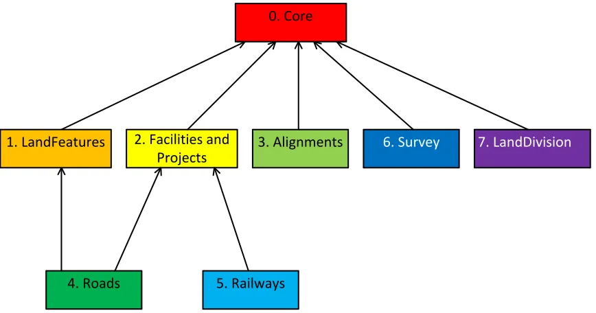
Some InfraGML Parts depend upon other parts:
0. Core
2. Facilities and Projects
6. Survey 7. LandDivision
3. Alignments
4. Roads 5. Railways
1. LandFeatures
Figure 1. InfraGML Part Dependencies
The boxes above represent InfraGML Parts. Arrows show Part dependencies. The Part dependencies derive from the dependencies of the InfraGML Requirements Classes contained in these Parts. The reader should rely more on the InfraGML Requirements Class dependencies and only use the Part dependencies as a guide for knowing which InfraGML Part standards to consider.
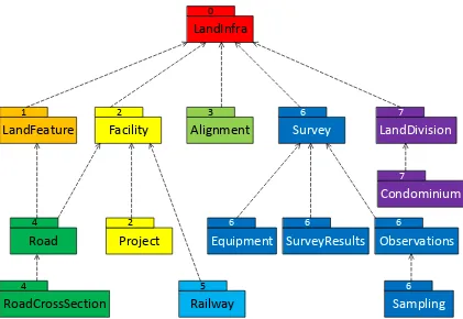
LandInfra
Figure 2. LandInfra Requirements Classes grouped into InfraGML Parts
The boxes above and their names represent LandInfra Requirements Classes. The numbers are InfraGML Part numbers. Dependency arrows shown above are dependencies between LandInfra Requirements Classes.
7.
Requirements Classes for this Part
7.1 Structural Overview of Requirements Classes
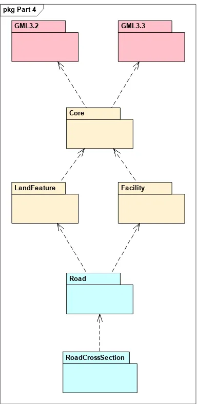
The Requirements Classes for this Part of the InfraGML encoding standard (shown in blue in Figure 3 below) are defined in this Clause 7. Requirements Classes from other Parts upon which this Part’s Requirements Classes are dependent (shown in beige in Figure 3 below) are listed here but defined in the documentation of their respective Parts. External OGC and ISO standards on which Requirements Classes in this Standard depend (shown in pink in Figure 3 below) are also listed. Below is a brief summary of the
Figure 3. Requirements Classes for this Part and their Dependencies
7.1.1 Requirement Classes Defined in This Part
Road
The Road Requirements Class supports those use cases in which a designer wishes to exchange the output of the design with someone who is likely to use it for purposes other than completing the road design. Consequently, the Road Requirements Class includes several alternative ways for representing a design such as with 3D RoadElements, 3D StringLines (aka profile views, longitudinal breaklines, long sections), and 3D surfaces and layers, as well as collections of these.
RoadCrossSection
pkg Part 4
Road
RoadCrossSection LandFeature
GML3.3 GML3.2
Core
The RoadCrossSection Requirements Class extends the Road Requirements Class by adding the 2D CrossSection alternative way of representing a design, as well as collections of these.
7.1.2 Dependent Requirement Classes Defined in Other Parts
The Requirements Classes defined in this Part are dependent on the following Requirements Classes from other Parts.
Part 0. LandInfra Core
LandInfra is the core Requirements Class and is the only mandatory Requirements Class. This class contains information about the Land and Infrastructure dataset that can contain information about facilities, land features, land division, documents, survey marks, surveys, sets, and feature associations. LandInfra also contains the definition of types common across other Requirements Classes, such as the Status CodeList.
Part 1. LandInfra LandFeature
Features of the land, such as naturally occurring water features and vegetation are specified in the LandFeature Requirements Class as land features. Also included are models of the land surface and subsurface layers. Improvements to the land such as the construction of an embankment or the planting of landscape material are considered to be part of Site Facilities in the Facility Requirements Class.
Part 2. LandInfra Facility
Facilities include collections of buildings and civil engineering works and their associated siteworks. The Facilities Requirements Class includes the breakdown of facilities into discipline specific facility parts and introduces the notion of elements which make up these parts. The Facilities Requirements Class only provides general support for facilities themselves, allowing subsequent Requirements Classes to focus on specific types of the parts that make up facilities, such as road and railway. This Requirements Class is optional in order to allow for the condition where all of the LandInfra dataset information is not facility related, such as one containing only survey or land division information.
7.1.3 Other Standards upon which the Requirement Classes of this Part Depend For external OGC and ISO standards on which Requirements Classes in this Standard depend, a brief summary of the function of each of these Standards is described below. GML 3.2
GML 3.3
OGC 10-129r1, OGC® Geography Markup Language (GML) — Extended schemas and encoding rules, v3.3 defines the linear referencing concepts (e.g., linear element, distance along, Linear Referencing Methods) used for linearly referenced locations in this
Standard.
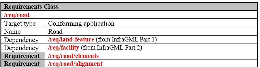
7.2 Requirements Class: Road
Requirements Class
/req/road
Target type Conforming application
Name Road
Dependency /req/land-feature(from InfraGML Part 1)
Dependency /req/facility(from InfraGML Part 2)
Requirement /req/road/elements
Requirement /req/road/alignment
7.2.1 Implementation decisions regarding OGC 15-111r1 UML
The following implementation decisions have been made regarding the OGC 15-111r1 Road Requirements Class UML:
1. In agreement with bSI, the geometry of a StringLine has been expanded beyond LineString to optionally include AlignmentCurve, if the application supports the Alignment Requirements Class from LandInfra Part 3 (where AlignmentCurve is defined). See 7.2.3. However, a LineString geometry is still required.
2. Because the Feature.FeatureID attribute was dropped from Core (see Part 0),
Road.roadID has been added. Because Element was removed from Part 2 Facilities and Projects, Road.roadElementID has been added. IDs have also been added for
RoadElementSet, StringLine, StringLineSet, Surface, and SurfaceSet. 7.2.2 Specific Requirements for this Requirements Class
Requirement /req/road/elements
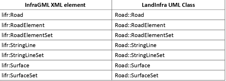
A conforming application shall support the Road XML elements listed in Table 1 in accordance with the GML XSD specified in
http://schemas.opengis.net/infragml/part4/1.0/road.xsd.
An application conforming to this standard shall support the Road XML elements listed below in Table 1 in accordance with the GML XSD specified in
shown with a XML namespace prefix of “lifr”. Corresponding LandInfra UML classes are shown with their LandInfra Requirements Class prefix of “Road”.
InfraGML XML element LandInfra UML Class
lifr:Road Road::Road
lifr:RoadElement Road::RoadElement
lifr:RoadElementSet Road::RoadElementSet
lifr:StringLine Road::StringLine
lifr:StringLineSet Road::StringLineSet
lifr:Surface Road::Surface
lifr:SurfaceSet Road::SurfaceSet
Table 1. InfraGML Road XML elements with corresponding LandInfra UML classes
A Road FacilityPart can be represented in any of four different ways: as RoadElements, Surfaces, StringLines, or RoadCrossSections (see the RoadCrossSection Requirements Class in 7.3 for the RoadCrossSections representation). These are four different views of the same Road: as a solid (typically), as faceted (triangular) surfaces, as lines running longitudinally at key parts of the Road, and as 2D views cut perpendicular to the Road centerline, respectively. An application conforming to this Road Requirements Class can include any of the first three representations, singularly or in combination. An
application conforming to the RoadCrossSection Requirements Class can also include the fourth representation alone or in combination with any of the other three. It is up to the application to ensure consistency between multiple representations of the same Road – InfraGML independently supports all four representations, but makes no assurances about consistency between them.
The four representations can be specified relative to some linear element, in accordance with OGC Abstract Specification Topic 19, Linear Referencing. If the application supports the InfraGML Alignment Requirements Class, then an Alignment can serve as the linearly locating linear element.
Requirement /req/road/alignment
If an application allows the linear element used for locating
7.2.3 StringLine geometry
The initial geometry type specified for StringLines in 15-111r1 was LineString. Since then, bSI has suggested expanding this to include AlignmentCurves. To maintain harmony, a second geometry type is added to StringLine:
alternativeGeometry: optional geometry as an AlignmentCurve 7.2.4 Road with Alignment Example (informative)
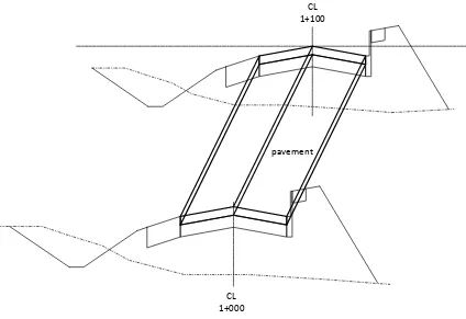
The Two Lane Road example in OGC 15-111r1, Clause 7.6.8, [LandInfra]
RoadCrossSection Requirements Class is the basis for the Road with Alignment example. Attention will be focused only on the top pavement layer. Figure 4 shows two cross sections based on the Two Lane Road with the top pavement layer between them.
CL 1+000
CL 1+100
pavement
Figure 4. Two Lane Road example
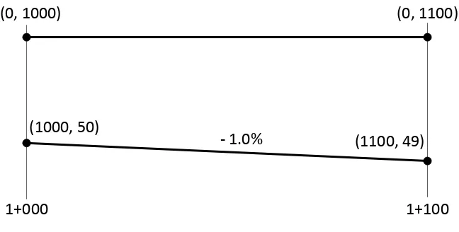
7.2.4.1 Alignment
The simple Alignment shown in Figure 5is used for locating the example road. It is specified by a single lineSegment Alignment2DHorizontal and a single line
1+000 1+100
(0, 1000) (0, 1100)
- 1.0% (1000, 50)
(1100, 49)
Figure 5. Alignment Plan and Profile views
The GML for the Alignment would be: <feature>
<lia:Alignment gml:id="a1"> <lia:alignmentID>
<lia:identifier>Alignment1</lia:identifier> </lia:alignmentID>
<lia:geometry>
<lia:AlignmentCurve gml:id="ac1"> <lia:horizontal>
<lia:Alignment2DHorizontal gml:id="ah1"> <lia:location>road centerline</lia:location> <lia:description></lia:description>
<lia:state>proposed</lia:state> <lia:segment>
<lia:tangentialContinuity>true</lia:tangentialContinuity> <lia:geometry>
<lia:lineSegment>
<gml:pos>0 1000</gml:pos> <gml:pos>0 1100</gml:pos> </lia:lineSegment>
</lia:geometry> </lia:segment>
</lia:Alignment2DHorizontal> </lia:horizontal>
<lia:vertical>
<lia:Alignment2DVertical gml:id="av1"> <lia:location>road centerline</lia:location> <lia:description></lia:description>
<lia:state>proposed</lia:state> <lia:segments>
<lia:tangentialContinuity>true</lia:tangentialContinuity> <lia:startDistAlong gml:id="sda1">
<gmllr:distanceAlong>1000</gmllr:distanceAlong> </lia:startDistAlong>
</lia:segments>
The GML which enables alignment ‘a1” to be measurable along as a linear element would also include:
<linearElement>
<LinearElement gml:id="le1">
<gmllr:feature xlink:href="a1" xlink:title="alignment a1"> </gmllr:feature>
<gmllr:defaultLRM xlink:href="lrm1"/>
<gmllr:measure uom="m">100</gmllr:measure> </LinearElement>
</linearElement>
Next, the GML which defines the Road FacilityPart of the campus Facility would be: <feature>
<lif:Facility gml:id="fac1"> <lif:facilityID>
<lif:identifier>101</lif:identifier> </lif:facilityID>
<lif:type>campus</lif:type>
<lif:status xlink:href="http://example.com/status#planned" xlink:title="Planned"/>
<lif:footprint xlink:href="poly1" xlink:title="Polygon"> </lif:footprint>
<lif:type xlink:href="http://example.com/facilityPartType#road" xlink:title="Road"/>
<lif:status xlink:href="http://example.com/status#designed" xlink:title="Designed"/>
<lifr:roadID>
<lifr:identifier>TwoLaneRoad</lifr:identifier> </lifr:roadID>
7.2.4.2 RoadElement Representation
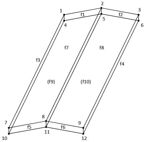
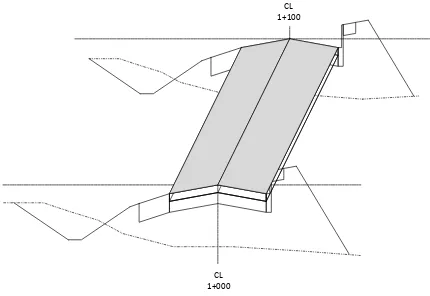
Figure 6 shows the top pavement layer represented as a single RoadElement.
CL 1+000
CL 1+100
Figure 6. Pavement as a RoadElement
1
2
3
4
5
6
7
8
9
10
11
12
f1 f2
f3
f4
f5 f6
f7 f8
(f9) (f10)
Figure 7. Pavement RoadElement PolyfaceMesh
Index X Y Z
1 -3.650 1100 48.927
2 0.000 1100 49.000
3 3.650 1100 48.927
4 -3.650 1100 48.862
5 0.000 1100 48.935
6 3.650 1100 48.862
7 -3.650 1000 49.927
8 0.000 1000 50.000
9 3.650 1000 49.927
10 -3.650 1000 49.862
11 0.000 1000 49.935
The GML for the pavement RoadElement would be: <lifr:element>
<lifr:RoadElement gml:id="re1">
<gmllr:DistanceExpression gml:id="de2">
<gmllr:distanceAlong>1100</gmllr:distanceAlong> </gmllr:DistanceExpression>
</gmllr:distanceExpression> </gmllr:PositionExpression> </toPosition>
</LinearFromToLocation> </linearlyReferencedLocation> <lifr:roadElementID>
<lifr:identifier>pavement1</lifr:identifier> </lifr:roadElementID>
<lifr:roadElementType
xlink:href="http://example.com/oadElementType#pavementSurfaceCourse" xlink:title="Pavement Surface Course"/>
<lifr:material>asphalt</lifr:material> </lifr:RoadElement>
</lifr:element>
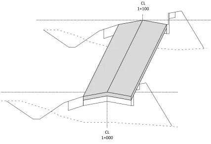
7.2.4.3 Surface Representation
Figure 8 shows the top surface of the top pavement layer represented as a single Surface. CL
1+100
CL 1+000
Figure 8. Pavement (Top) Surface Representation
(-3.65,1000,49.927)
(-3.65,1100,48.927)
(3.65,1000,49.927)
(3.65,1100,48.927)
(0,1000,50)
(0,1100,49)
Figure 9. Pavement Triangulated (Top) Surface
The GML for the pavement Surface would be: <lifr:surface>
<lifr:Surface gml:id="sur1">
<gml:description>top surface after construction is completed</gml:description> <gml:name>top surface</gml:name>
<lifr:surfaceID>
<lifr:identifier>surface1</lifr:identifier> </lifr:surfaceID>
<lifr:geometry gml:id="tin1" xsi:type="tin:TINType"> <gml:trianglePatches>
<tin:SimpleTrianglePatch>
<gml:pos>-3.650 1100 48.927</gml:pos> <gml:pos>-3.650 1000 49.927</gml:pos> <gml:pos>0.000 1000 50.000</gml:pos> </tin:SimpleTrianglePatch>
<tin:SimpleTrianglePatch>
<gml:pos>0.000 1000 50.000</gml:pos> <gml:pos>0.000 1100 49.000</gml:pos> <gml:pos>-3.650 1100 48.927</gml:pos> </tin:SimpleTrianglePatch>
<tin:SimpleTrianglePatch>
<gml:pos>0.000 1100 49.000</gml:pos> <gml:pos>0.000 1000 50.000</gml:pos> <gml:pos>3.650 1000 49.927</gml:pos> </tin:SimpleTrianglePatch>
<tin:SimpleTrianglePatch>
</lifr:Surface> </lifr:surface>
7.2.4.4 StringLine Representation
Figure 10 shows the top pavement layer represented as a set of three StringLines. CL
1+100
CL 1+000
Figure 10. Pavement StringLine Representation
(-3.65,1000,49.927)
(-3.65,1100,48.927)
(3.65,1000,49.927)
(3.65,1100,48.927)
(0,1000,50)
(0,1100,49)
LEP CLP REP
Figure 11. Pavement StringLines
The GML for the pavement StringLineSet would be: <lifr:stringLineSet>
<lifr:StringLineSet gml:id="sls1">
<gml:description>string lines delineating the top pavement surface</gml:description> <gml:name>top surface pavement</gml:name>
<lifr:stringLineSetID>
<lifr:identifier>pavement1</lifr:identifier> </lifr:stringLineSetID>
<lifr:stringLine>
<lifr:StringLine gml:id="sl1">
<gml:description>top surface</gml:description> <gml:name>left edge pavement</gml:name> <lifr:stringLineID>
<lifr:identifier>LEP</lifr:identifier> </lifr:stringLineID>
<lifr:geometry gml:id="ls1">
<gml:pos>-3.650 1000 49.927</gml:pos> <gml:pos>-3.650 1100 48.927</gml:pos> </lifr:geometry>
</lifr:StringLine> </lifr:stringLine> <lifr:stringLine>
<lifr:StringLine gml:id="sl2">
<gml:description>top surface</gml:description> <gml:name>centerline pavement</gml:name> <lifr:stringLineID>
<lifr:identifier>CLP</lifr:identifier> </lifr:stringLineID>
<lifr:geometry gml:id="ls2">
<lifr:alternativeGeometry xlink:href="ac1"></lifr:alternativeGeometry> </lifr:StringLine>
</lifr:stringLine> <lifr:stringLine>
<lifr:StringLine gml:id="sl3">
<gml:description>top surface</gml:description> <gml:name>right edge pavement</gml:name> <lifr:stringLineID>
<lifr:identifier>REP</lifr:identifier> </lifr:stringLineID>
<lifr:geometry gml:id="ls3">
<gml:pos>3.650 1000 49.927</gml:pos> <gml:pos>3.650 1100 48.927</gml:pos> </lifr:geometry>
</lifr:StringLine> </lifr:stringLine> </lifr:StringLineSet> </lifr:stringLineSet>
7.3 Requirements Class: RoadCrossSection
Requirements Class
/req/road-cross-section
Target type Conforming application
Name Road
Dependency /req/road
Requirement /req/road-cross-section/elements
Requirement /req/road-cross-section/alignment
7.3.1 Implement decisions regarding OGC 15-111r1 UML
The following implement decisions have been made regarding the OGC 15-111r1 Road Cross Sections Requirements Class UML.
1. In order to implement the split between the Road and RoadCrossSection Requirements Classes, it was necessary to create the RoadWithCrossSection subtype of Road which extends Road to include optiional CrossSections and CrossSectionSets.
2. IDs have been added for CrossSections and CrossSectionSets. 7.3.2 Specific Requirements for this Requirements Class
Requirement /req/road-cross-section/elements
An application conforming to this standard shall support the Road XML elements listed below in Table 3 in accordance with the GML XSD specified in
http://schemas.opengis.net/infragml/part4/1.0/road.xsd. Road XML element names are shown with a XML namespace prefix of “lifrcs”. Corresponding LandInfra UML classes are shown with their LandInfra Requirements Class prefix of “RoadCrossSection”.
InfraGML XML element LandInfra UML Class
lifrcs:CrossSection RoadCrossSection::CrossSection
lifrcs:CrossSectionArea RoadCrossSection::CrossSectionArea
lifrcs:CrossSectionComponent RoadCrossSection::CrossSectionComponent
lifrcs:CrossSectionPoint RoadCrossSection::CrossSectionPoint
lifrcs:CrossSectionSet RoadCrossSection::CrossSectionSet
lifrcs:RoadWithCrossSection InfraGML RoadCrossSection::RoadWithCrossSection
Table 3. InfraGML Road Cross Section XML elements with corresponding LandInfra UML classes
The RoadCrossSection Requirements Class provides the fourth way of representing a Road FacilityPart: as 2D views cut perpendicular to the Road centerline. Because this Requirements Class is dependent upon the Road Requirements Class, an application conforming to this RoadCrossSection Requirements Class can include any of the four representations, singularly or in combination. It is up to the application to ensure consistency between multiple representations of the same Road – InfraGML independently supports all four representations, but makes no assurances about consistency between them.
The cross section representation can be specified relative to some linear element, in accordance with OGC Abstract Specification Topic 19, Linear Referencing. If the application supports the InfraGML Alignment Requirements Class, then an Alignment can serve as the linearly locating linear element.
Requirement /req/road-cross-section/alignment
If an application allows the linear element used for locating CrossSections to be an Alignment, then that application shall support the Alignment Requirements Class.
7.3.3 Road with Alignment Example Continued (informative)
7.3.3.1 CrossSection Representation
Figure 12 shows the top pavement layer represented by two CrossSections.
CL
1+100
CL 1+000
Figure 12. Pavement CrossSection Representation
A closer look at the pavement in Figure 13 shows the pavement CrossSectionComponent contained in the two CrossSections included in the CrossSection representation. The component is the same for both CrossSections. The CrossSections are at Alignment stations 1+000 and 1+100. The two CrossSections are grouped together in a
CrossSectionSet called “TwoLaneRoadCrossSections”.
REP
REP_BOT CLP
CLP_BOT
LEP_BOT
LEP 2% .073
.065
3.65
CrossSectionPoints are center line of pavement top (CLP), right edge of pavement top (REP), right edge of pavement bottom (REP_BOT), center line of pavement bottom (CLP_BOT), and left edge of pavement bottom (LEP_BOT), and left edge of pavement top (LEP). The coordinates for the CrossSectionPoints are shown in Table 4.
name description horizontal vertical
CLP centerline pavement 0.000 0.000
REP right edge of pavement 3.650 -0.073
REP_BOT right edge of pavement 3.650 -0.138
CLP_BOT centerline pavement
The GML for the pavement CrossSectionComponent part of the CrossSection representation would be:
<feature>
<lifrcs:RoadWithCrossSection gml:id="r2"> <lif:facilityPartID>
<lif:identifier>Road2</lif:identifier> </lif:facilityPartID>
<lif:type xlink:href="http://example.com/facilityPartType#road" xlink:title="Road"/>
<lif:status xlink:href="http://example.com/status#designed" xlink:title="Designed"/>
<lifr:roadID>
<lifr:identifier>TwoLaneRoad</lifr:identifier> </lifr:roadID>
<lifr:approximateWidth uom="m">13</lifr:approximateWidth> <lifrcs:crossSectionSet>
<lifrcs:identifier>TwoLaneRoadCrossSections</lifrcs:identifier> </lifrcs:crossSectionSetID>
<gml:description>bottom of finished surface</gml:description>
<lifrcs:horizontalDisplacement uom="m">0</lifrcs:horizontalDisplacement> <lifrcs:verticallDisplacement uom="m">0</lifrcs:verticallDisplacement> <lifrcs:component xlink:href="csc1"/>
</lifrcs:CrossSection> </lifrcs:crossSection> </lifrcs:CrossSectionSet> </lifrcs:crossSectionSet> </lifrcs:RoadWithCrossSection>
</feature>
8.
Media Types for any data encoding(s)
Annex A:
Conformance Class Abstract Test Suite (Normative)
A.1 Conformance class: Road
/conf/road
Requirements /req/road
Dependency /conf/land-feature(from InfraGML Part 1)
Dependency /conf/facility(from InfraGML Part 2)
Test /conf/road/elements
Requirement /req/road/elements
Test purpose Verify that the conforming application supports the Road XML elements listed in Table 1 in accordance with the GML XSD specified in
http://schemas.opengis.net/infragml/part4/1.0/road.xsd. Test method Inspect the GML output to verify the above
requirement. Test type Capability
Test /conf/road/alignment
Requirement /req/road/alignment
Test purpose Verify that if the application allows the linear element used for locating RoadElements to be an Alignment, or if it allows the StringLine curve geometry to be of type AlignmentCurve, then that application shall support the Alignment Requirements Class.
Test method Inspect the application to verify the above requirement is satisfied.
Test type Capability
A.2 Conformance class: RoadCrossSection
/conf/road-cross-section
Requirements /req/road-cross-section Dependency /conf/road
Test /conf/road-cross-section/elements
Requirement /req/road-cross-section/elements
Test purpose Verify that the conforming application supports the Road Cross Section XML elements listed in Table 3 in
accordance with the GML XSD specified in
http://schemas.opengis.net/infragml/part4/1.0/roadcrossse ction.xsd.
Test method Inspect the GML output to verify the above requirement.
Test type Capability
Test /conf/road-cross-section/alignment
Test purpose Verify that if the application allows the linear element used for locating CrossSections to be an Alignment, then that application shall support the Alignment Requirements Class.
Test method Inspect the application to verify the above requirement is satisfied.
Annex B:
Sample XML (Informative)
The following XML instance documents attempt to demonstrate the use of most all of the elements supported by the specified Requirements Class(es), including all optional properties. All values are exemplary only and not intended to represent actual real world instance values. Not all xlink references are resolvable within this document.
B. 1 Complete Road (less Cross Sections) XML
Example from Part4Road0410.xsd
<name>Sample Part4a Dataset</name>
<description>LandInfra dataset to test all possible content for Part4 Road (without Cross Sections)
</description>
<dateTime>2016-12-02T10:00:00</dateTime> <datasetVersion>1.0</datasetVersion> <application>manual</application>
<author>Paul Scarponcini, Bentley Systems, Inc.</author> <infraVersion>1.0</infraVersion>
<language>English</language> <defaultCRS xlink:href="crs1"/> <feature>
<lia:Alignment2DHorizontal gml:id="ah1">
<LinearElement gml:id="le1">
<gmllr:feature xlink:href="a1" xlink:title="alignment a1"> </gmllr:feature>
<gmllr:defaultLRM xlink:href="lrm1"/>
<gmllr:measure uom="m">100</gmllr:measure> </LinearElement>
</linearElement> <feature>
<lif:Facility gml:id="fac1"> <lif:facilityID>
</lif:facilityID>
<lif:type>campus</lif:type>
<lif:status xlink:href="http://example.com/status#planned" xlink:title="Planned"/>
<lif:footprint xlink:href="poly1" xlink:title="Polygon"> </lif:footprint>
<lif:type xlink:href="http://example.com/facilityPartType#road" xlink:title="Road"/>
<lif:status xlink:href="http://example.com/status#designed" xlink:title="Designed"/>
<lifr:approximateWidth uom="m">13</lifr:approximateWidth> <lifr:element>
<lifr:RoadElement gml:id="re1">
<SimpleIndexedPolygon gml:id="f10">
xlink:href="http://example.com/oadElementType#pavementSurfaceCourse" xlink:title="Pavement Surface Course"/>
<gml:description>top surface after construction is completed</gml:description> <gml:name>top surface</gml:name>
</lifr:ID>
<lifr:stringLine>
B. 2 Complete Road Cross Section XML
xmlns:lifr="http://www.opengis.net/infragml/road/1.0"
<name>Sample Part4b Dataset</name>
<description>LandInfra dataset to test all possible content for Part4 Road Cross Sections </description>
<dateTime>2016-12-02T10:00:00</dateTime> <datasetVersion>1.0</datasetVersion> <application>manual</application>
<author>Paul Scarponcini, Bentley Systems, Inc.</author> <infraVersion>1.0</infraVersion>
<language>English</language> <defaultCRS xlink:href="crs1"/> <feature>
<lifrcs:RoadWithCrossSection gml:id="r2"> <lif:facilityPartID>
<lif:ID>
<identifier>Road2</identifier> </lif:ID>
</lif:facilityPartID>
<lif:type xlink:href="http://example.com/facilityPartType#road" xlink:title="Road"/>
<lif:status xlink:href="http://example.com/status#designed" xlink:title="Designed"/>
<lifrcs:ID>
<identifier>1+100</identifier> </lifrcs:ID>
</lifrcs:crossSectionID>
<lifrcs:locatedAlong xlink:href="a1"></lifrcs:locatedAlong> <lifrcs:distanceAlong>
<gmllr:DistanceExpression gml:id="de2">
<gmllr:distanceAlong>1100</gmllr:distanceAlong> </gmllr:DistanceExpression>
</lifrcs:distanceAlong>
<lifrcs:horizontalDisplacement uom="m">0</lifrcs:horizontalDisplacement> <lifrcs:verticallDisplacement uom="m">0</lifrcs:verticallDisplacement> <lifrcs:component xlink:href="csc1"/>
</lifrcs:CrossSection> </lifrcs:crossSection> </lifrcs:CrossSectionSet> </lifrcs:crossSectionSet> </lifrcs:RoadWithCrossSection>
</feature>
Annex C:
Revision history
Date Release Author Paragraph modified
Description
20170307 104r1 Scarponcini Figure 2 Dependency changes in Part 6 20170410 104r2 Paul
Scarponcini