PERFORMANCE OF LARGE-FORMAT DIGITAL CAMERAS
K. Jacobsen
Institute of Photogrammetry and GeoInformation, Leibniz University Hannover, Germany
[email protected]
Inter-commission WG III/I
KEY WORDS: photogrammetry, analysis, camera, geometric, radiometric, quality
ABSTRACT:
Based on test blocks and standard production blocks Z/I Imaging DMCII-140, 230 and 250 as well as UltraCam Eagle images have been analyzed by bundle block adjustment with self calibration. By analysis of image coordinate residuals it is possible to check remaining systematic image errors and to update the set of additional parameters to the required combination. The Hannover program BLUH is using a basic set of 12 additional parameters which is a combination between geometric parameters and Fourier parameters in polar coordinates. In addition it is necessary to use a set of special additional parameters for the combination of the 9 UltraCam sub-CCDs. CCDs are often not flat enough, causing a bending of the edges. For the correct handling of such effects, special additional parameters are required to eliminate or at least reduce remaining systematic effects at image corners.
For all DMCII-blocks with 5cm, 7cm, 9cm and 20cm GSD the root mean square size of the systematic image errors with 0.05pixels is very small. Only the basic set of 12 additional parameters is required, the special parameters for the image corners did not improve the accuracy determined with independent check points. Against former results with UltraCam images the monolithic stitching of the panchromatic sub-images to the green image improved the image geometry, nevertheless for reaching the highest accuracy the full set of 52 additional parameters is required, leading to systematic image errors in the root mean square of approximately 0.2pixels. This seems to be small, but it is causing a model deformation up to more as 1.0 GSD in the height, while in the case of the DMCII-images the model deformation did not exceed 0.2 GSD in Z. The major reason for the UltraCam Eagle image deformation seems to be caused by corner effects of the green reference image. Such an effect can be avoided with a better calibration.
The DMCII and the UltraCam Eagle images were improved by the firm ware for edge enhancement, influencing also the effective image resolution, determined by edge analysis. No real loss of the effective against the nominal resolution can be seen. Nevertheless the UltraCam Eagle images are a little noisy, which may be caused by the edge enhancement and by the imaging in January.
1. INTRODUCTION
Digital aerial cameras have replaced analogue cameras for most applications. The advantage of the digital cameras is obvious – the image quality of original digital images is better, the information contents of large format digital cameras is quite higher, the sensitivity is improved and the difficult and expensive film processing is eliminated. With the second generation of Z/I Imaging DMC, using a monolithic large CCD-array for the panchromatic sub-camera (Stoldt 2010), the geometric problems of merging sub-images together do not exist anymore. Vexcel improved the fusion of the sub-images by the so called monolithic stitching (Ladtstädter et al. 2010) in fitting the UltraCam sub-images to the monolithic green image. Of course the green UltraCam channel has a lower resolution as the panchromatic images; nevertheless this improved the image geometry clearly.
The changes of the hardware and the handling require a geometric analysis of the actual large format digital cameras by self-calibration with additional parameters which has been done with the Hannover program system BLUH.
2. SELF-CALIBRATION
For the self-calibration different sets of additional parameters exist. The former often used Ebner parameters during the evaluation test of the German Society of Photogrammetry and Remote Sensing (Jacobsen et al. 2010) has been shown as not
useful for digital camera images, while the extension to the Grün-parameters was helpful for determination and consideration of systematic image errors. Nevertheless the Grün-parameters are general parameters, not able to respect special geometric problems. The author included into program system BLUH a basic set of 12 additional parameters, usable for any camera, special parameters for the cameras merging sub-images together and 8 additional parameters for improving the results at the image corners because CCD-arrays not in any case are satisfying flat, which can be seen especially at the image corners. The basic set of parameters includes 7 parameters with physical specification and 5 parameters mathematical defined to be able to describe any general type of systematic image errors (table 1). In case of equal distribution of the image points, the parameters have a low correlation – the correlations are lower as in the case of the Ebner parameter set. Program BLUH analyzes the parameters for significance, correlation and total correlations and eliminates not required parameters automatically, so in the final iteration a smaller number of additional parameters is used as in the beginning. For the handling of first version DMC-images, based on 4 sub-cameras, 8 parameters are available, but finally it has been shown that just one special parameter was required, covering the effect of a common change of the focal length, looking as a butterfly. For the correct handling of UltraCam images, with the exception of the central sub-CCD all other 8 sub-CCDs can be improved by scale, shift in X and Y and perspective transformation (table 2).
By analysis of the residuals (remaining image coordinate discrepancies) the not respected systematic image errors are estimated. All residuals are overlaid corresponding to the image coordinates and averaged in selectable number of image sub-units. This shows very well if the used set of additional parameters is satisfying. The requirement of the special additional parameters 81 up to 88 for improving the image corners in radial and tangential direction was justified by this analysis.
________________________________________________ x, y = image coordinates normalized to maximal radial distance 162.6mm (with scale factor for parameters 9 up to 11= 162.6 / maximal radial distance) r² = x² + y² b = arctan (y/x) Pn = size of additional parameter
1. x' = x - y• P1 y' = y - x• P1 angular affinity 2. x' = x - x• P2 y' = y + y• P2 affinity 3. x' = x - x• cos 2b • P3 y' = y - y• cos 2b • P3 4. x' = x - x• sin 2b • P4 y' = y - y• sin 2b • P4 5. x' = x - x• cos b • P5 y' = y - y• cos b • P5 6. x' = x - x• sinb • P6 y' = y - y• sin b • P6
7. x' = x + y• r• cos b • P7 y' = y - x• r• cos b • P7 tangential distortion 1
8. x' = x + y• r• sin b • P8 y' = y - x• r• sin b • P8 tangential distortion 2
9. x' = x - x• (r²-16384) • P9 y’ = y - y• (r² - 16384) • P9 radial symmetric r³ 10. x ' = x - x• sin(r • 0.049087) • P10
y' = y - y• sin(r • 0.049087) • P10 radial symmetric 11. x' = x - x• sin(r • 0.098174) • P11
y' = y - y*sin(r • 0 0.098174) • P11 radial symmetric 12. x' = x - x• sin 4b • P12 y' = y - y• sin 4b • P12
__________________________________________________________________________________________________________________________________________________
Table 1. Basic set of additional parameters in BLUH
__________________________________________________ 42 – 49 scale parameters for UltraCam
50 – 57 shift X parameters for UltraCam 58 – 65 shift Y parameters for UltraCam 66 – 73 UltraCam master images perspective
79 common deformation of DMC (version 1) sub-images 81-88 parameters for geometry at image corners (problem of CCD flatness) e.g.
81. x’ = x + P81*ABS(x³ * y³) * 10-9 tangential for y’ = y - P81*ABS(x³ * y³) * 10-9 lower right quarter 85. x’ = x + P85*x² * y² * 10-6 radial for y’ = y + P85*x2 * y² * 10-6 lower right quarter
_______________________________________________________________________________________________________________________________________________
Table 2. special additional parameters in BLUH
3. HANDLED DATA SETS
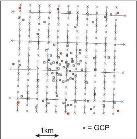
DMCII-140, DMCII-230 and DMCII-250 have been analyzed based on three different flying heights with approximately 5cm, 9cm and 15cm GSD for all three cameras. This was supported by an operational block taken with the DMCII-230 with 7cm GSD. The operational block of the city of Hannover with 957 images has 60% end lap and 40% side lap, while the other blocks have 60% end lap, 60% side lap and in addition crossing flight lines with similar overlap, only the 15cm GSD flights have 80% overlap in both directions together with same in crossing flight direction. Between 49 and 1630, in the average 730, points are located in every image of the operational block while the test blocks in the average have slightly above 200 points per image.
The UltraCam Eagle camera of Keystone Aerial Surveys with 79.8mm focal length was investigated in a different area with 60% end lap, 60% side lap in a lower flying height
corresponding to 5cm GSD and with the same overlap from higher flying elevation corresponding to 15cm GSD in crossing flight direction. The data set includes 15 up to 1300 points per image, in the average 115 points are in each of the 226 images. All block adjustments have been computed without information about direct sensor orientation.
5cm GSD 9cm GSD
15cm GSD Operational block, 7cm GSD Figure 1: arrangement of DMCII-flights with control points in red and independent check points in black
Figure 2: UltraCam Eagle flight
4. SYSTEMATIC IMAGE ERRORS
4.1 DMCII
The panchromatic sub-camera of the DMCII-versions has a large size monolithic CCD-array. No merging of sub-images is required, corresponding to this no special additional parameters have to be used. Only with the basic 12 parameters and optional in addition the 8 additional parameters for the image corners the block adjustments had to be handled.
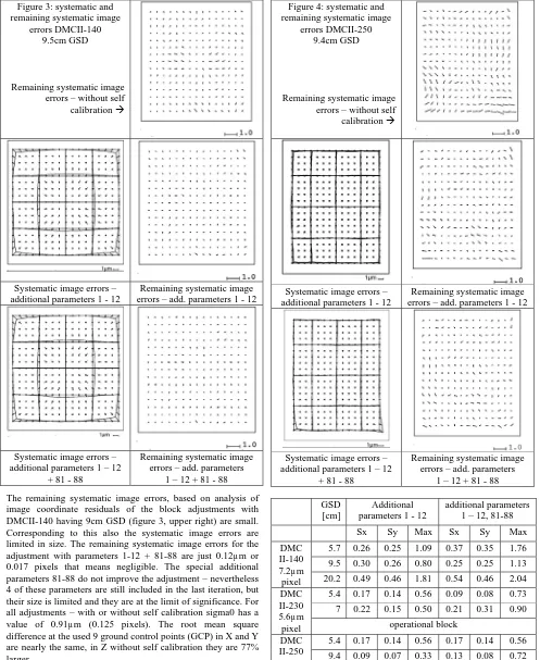
Figure 3: systematic and remaining systematic image
errors DMCII-140 9.5cm GSD
Remaining systematic image errors – without self calibration
Systematic image errors – additional parameters 1 - 12
Remaining systematic image errors – add. parameters 1 - 12
Systematic image errors – additional parameters 1 – 12
+ 81 - 88
Remaining systematic image errors – add. parameters
1 – 12 + 81 - 88
The remaining systematic image errors, based on analysis of image coordinate residuals of the block adjustments with DMCII-140 having 9cm GSD (figure 3, upper right) are small. Corresponding to this also the systematic image errors are limited in size. The remaining systematic image errors for the adjustment with parameters 1-12 + 81-88 are just 0.12µm or 0.017 pixels that means negligible. The special additional parameters 81-88 do not improve the adjustment – nevertheless 4 of these parameters are still included in the last iteration, but their size is limited and they are at the limit of significance. For all adjustments – with or without self calibration sigma0 has a value of 0.91µm (0.125 pixels). The root mean square difference at the used 9 ground control points (GCP) in X and Y are nearly the same, in Z without self calibration they are 77% larger.
SX SY SZ
No self calibration 3.5 3.0 6.4
Add. parameters 1-12 3.5 3.1 4.6
Add. parameters 1-12 + 81-88 3.5 3.0 4.5 Table 4: discrepancies at independent check points [GSD]
DMCII-140 9.5cm GSD
Figure 4: systematic and remaining systematic image
errors DMCII-250 9.4cm GSD
Remaining systematic image errors – without self calibration
Systematic image errors – additional parameters 1 - 12
Remaining systematic image errors – add. parameters 1 - 12
Systematic image errors – additional parameters 1 – 12
+ 81 - 88
Remaining systematic image errors – add. parameters
1 – 12 + 81 - 88
GSD [cm]
Additional parameters 1 - 12
additional parameters 1 – 12, 81-88
Sx Sy Max Sx Sy Max
5.7 0.26 0.25 1.09 0.37 0.35 1.76
9.5 0.30 0.26 0.80 0.25 0.25 1.13 DMC
II-140 7.2µm
pixel 20.2 0.49 0.46 1.81 0.54 0.46 2.04 5.4 0.17 0.14 0.56 0.09 0.08 0.73
7 0.22 0.15 0.50 0.21 0.31 0.90 DMC
II-230 5.6µm
pixel operational block
5.4 0.17 0.14 0.56 0.17 0.14 0.56
9.4 0.09 0.07 0.33 0.13 0.08 0.72 DMC
II-250 5.6µm
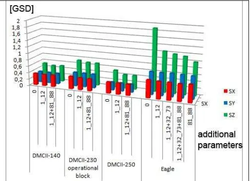
pixel 15.6 0.13 0.16 0.50 0.14 0.16 0.99 Table 5: square mean and maximal size of systematic image errors [µm]
The size of the systematic image errors of the DMCII-230 and the DMCII-250 are similar (table 4), for the DMCII-140 they are slightly larger, but absolutely small. This has to be seen in relation to the pixel size which is 7.2µm for the DMCII-140 and
5.6µm for the other. In the root mean square average the systematic image errors are up to 0.053 pixels that means very small. The remaining systematic image errors of the DMCII-250 for 9cm GSD (figure 4) indicate with the lowest line of points a systematic effect in x-direction. This cannot be compensated with the standard additional parameters (1-12), but with the special parameters for the corners 81-88 in addition. The remaining systematic image errors for the DMCII-250 corresponding to the additional parameters 1-12 + 81-88 do not indicate any more systematic image errors, their size of 0.23 µm or 0.041 pixels root mean square can be neglected for model handling. The systematic image errors of the DMCII-230 and DMCII-250 for the blocks with the other ground resolution are similar and not shown by this reason.
add. par 1-12 add. par 1-12 + 81-88
RMS maximal RMS maximal
DMCII-140 0.049 0.171 0.053 0.228 DMCII-230 0.030 0.095 0.035 0.146 DMCII-250 0.034 0.082 0.025 0.136
Table 6: root mean square and maximal size of systematic image errors [pixel]
SX SY SZ
No self calibration 0.36 0.34 0.53
Add. parameters 1-12 0.35 0.33 0.48 Add. parameters 1-12 + 81-88 0.36 0.33 0.50 Table 7: discrepancies at independent check points [GSD]
DMCII-230 5.4cm GSD
SX SY SZ
No self calibration 0.34 0.25 0.53
Add. parameters 1-12 0.34 0.25 0.42 Add. parameters 1-12 + 81-88 0.34 0.25 0.42 Table 8: discrepancies at independent check points [GSD]
DMCII-250 9.4cm GSD
All data sets of the DMCII show an improvement of the object point heights of independent check points by adjustment with the standard additional parameters, while the special additional parameters 81-88 do not lead to a further improvement. The horizontal coordinates of the check points are only negligible influenced by the systematic image errors.
4.2 UltraCam Eagle
Systematic image errors – additional parameters: only
81 - 88
Remaining systematic image errors – add. Parameters:
only 81 - 88
Figure 5: systematic and remaining systematic image errors UltraCam Eagle only with additional parameters 81 - 88 Figure 6: systematic and
remaining systematic image errors UltraCam Eagle
5cm GSD
Remaining systematic image errors – without self calibration
Systematic image errors – additional parameters 1 - 12
Remaining systematic image errors – add. parameters 1 - 12
Systematic image errors – additional parameters 1 – 12
+ 42 - 73
Remaining systematic image errors – add. parameters
1 – 12 + 42 - 73
Systematic image errors – additional parameters 1 – 12
+ 42 – 73 + 81 - 88
Remaining systematic image errors – add. parameters 1 – 12 + + 42 – 73 + 81 - 88
The UltraCam Eagle is fusing the 9 panchromatic sub-images of the 4 sub-cameras together. With the so called “monolithic stitching” (Ladstädter et al. 2010) the panchromatic sub-images are fitted to the green image which is based on one CCD-array with approximately linear three times lower resolution. This stitching improved the image geometry clearly against the former merging of sub-images; nevertheless the special additional parameters for the sub-images (parameters 32-73) have to be checked.
The remaining systematic image errors of the block adjustment without self calibration (fig. 6 upper) clearly indicate systematic image errors. But also the block adjustment with the basic additional parameters 1-12 and also the block adjustment with parameters 1-12 + 32-73 show clearly remaining systematic image errors, requiring the whole set of parameters 1 – 12 + 42 – 73 + 81 – 88. Of course from these 52 additional parameters only 23 are not removed by program BLUH, but the finally used additional parameters are belonging to the 3 groups of parameters.
The final systematic image errors based on the additional parameters 1 – 12 + 42 – 73 + 81 – 88 have a shape which approximately can be generated just with the parameters 81 – 88 (figure 5), but the remaining systematic image errors corresponding just to parameters 81-88 indicate some remaining systematic errors caused by the structure of the 9 sub-images. Nevertheless these remaining effects are not very large and the accuracy of the ground coordinates (table 10) is optimal if just the special parameters 81-88 are used. Such an image deformation can be explained by missing flatness of the green CCD-array. It may be solved by a proper pre-calibration of the camera.
Sx Sy Max
Additional parameters 1 - 12 0.40 0.52 1.87 Additional parameters 1 – 12 +
42 - 73
0.51 0.55 2.69
Additional parameters 1 – 1212 + 42 – 73 + 81 - 88
0.40 0.56 2.69
Additional parameters only 81-88 0.47 0.51 3.46 Table 9: square mean and maximal size of systematic image errors of UltraCam Eagle [µm] 5.2µm pixel size
SX SY SZ Table 10: discrepancies at independent check points [GSD]
UltraCam Eagle 5cm GSD
As for the DMCII the horizontal coordinates of independent check points are not influenced by the systematic image errors – this can be explained by in the average 12.1 images for the check points (table 11). On the other hand the vertical accuracy requires an improvement by the self calibration.
5. OBJECT POINT ACCURACY
With the exception of the operational DMCII-230 block, having just 60% end lap and 40% side lap, all blocks have a strong overlap as shown in figures 1 and 2.
DMCII-230 operational block 7 cm 3.7
DMCII-250 5cm 7.0
DMCII-250 9.4cm 12.7
DMCII-250 15cm 14.2
UltraCam Eagle 5cm 12.1
Table 11: average number of images per check point
With the exception of the operational block taken with the DMCII-230, the DMCII-230 block with 5.4cm GSD and the DMCII-250 block with 5cm GSD in the average 10 up to 14 images per check point are available.
Figure 7: object point accuracy determined at independent check points
With the operational DMCII-230 block slightly larger root mean square errors at check points in the units of GSD has been reached as with the other DMCII blocks. This can be explained by the just 3.7 images per check point and the situation that the object point coordinates of the control and check points are not optimal. For all blocks the self calibration does not improve the horizontal coordinates, while this is different for the height. For all DMCII blocks the special additional parameters 81 – 88 are not leading to a further improvement the object point coordinates (figure 7) against the basic set of additional parameters.
The behavior of the UltraCam Eagle is different. At first the discrepancies at the independent check points are quite larger (figure 7, table 10). This partially can be explained by not so precise horizontal control and check point coordinates. More important is the change of the vertical accuracy depending upon the self calibration. The accuracy of the given object height values are the same as for the DMCII blocks.
Corresponding to the systematic image errors and the remaining systematic image errors (figures 5 and 6) more additional parameters are required to determine and respect the systematic image errors. The root mean square of the check point height discrepancies (table 10) is reduced by 34% based on bundle block adjustment with the standard parameters 1-12 and further by 5% with the special UltraCam parameters 32-74 improving the locations of the 9 individual CCD-arrays. Also with the special parameters for the image corners a further improvement of the height by 3% could be reached.
The size of the systematic image errors based on the full set of additional parameters shows some similarities to the effect just caused by parameters 81 up to 88 (figure 5). So an adjustment just with these parameters has been made. The remaining systematic image errors are indicating some effects caused by merging the 9 panchromatic sub-images. Nevertheless with just this parameter set even more accurate height values have been reached (table 10). With parameters 32-74 in addition to 81-88 nearly the same larger root mean square differences at check point as with the whole set of parameters has been reached even if this is reducing the remaining systematic image errors from
0.21µm to 0.18µm or 0.035 pixels indicating no clear remaining systematic errors.
6. MODEL DEFORMATION
If the data acquisition software is able to respect the determined systematic image errors by on-line correction, the size and shape of the systematic image errors are not important. But not any software package is able to respect systematic image errors. This is causing a model deformation especially in the height. As seen before the horizontal coordinates are nearly not influenced by the systematic image errors. If the vertical component is not important, as for most map updates, the model deformation can be neglected, but if the height determination is critical and the used data acquisition software cannot respect the image deformation, the model deformation has to be checked.
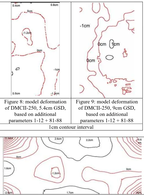
Figure 8: model deformation
Figure 10: model deformation of UltraCam Eagle based on additional parameters 1-12 + 32-73 + 81-88, 5cm GSD
1cm contour interval
The model deformation has been computed with randomly selected image models of the used data sets. Corresponding to the size of the systematic image errors and the height to base relation, the model deformation for the UltraCam Eagle was expected as quite larger as for the DMCII-250.
Both shown model deformations of the DMCII-250 (figures 8 and 9) are limited in size. Both reach up to 1.2cm model deformation corresponding to 0.22 respectively 0.13GSD. In relation to an operational vertical standard deviation of approximately 1 GSD this can be accepted.
This is different for the UltraCam Eagle, it shows up to 11.4cm deformation in Z (2.3 GSD) in one corner. Of course usually no data acquisition will be made in extreme corners, but model
deformations > 1 GSD cannot be avoided and this has to be respected because it has approximately the size of the accuracy itself.
Table 12: factor for effective image quality
By edge analysis the effective image quality has been checked (Jacobsen 2009) (table 12). All the images have been edge enhanced, reducing the factor for the effective image quality, but enlarging the noise. For the UltraCam Eagle the factor for the effective image quality nearly is 1.0, so the effective image quality corresponds to the nominal resolution. For the DMCII the factor is even below 1.0 indicating a higher radiometric image quality.
A noise analysis gave an average noise of the DMCII-images of 1.8, while it is 2.8 for the UltraCam Eagle. The larger noise of the UltraCam images may be explained by the photo flight in January.
CONCLUSION
The image geometry presented by systematic image errors is a very important topic for reaching high geometric accuracy of photogrammetric products. The used set of additional parameters must be able to describe the systematic image errors. In addition it should be checked whether remaining systematic image errors exist and it may be necessary to extend the set of additional parameters if larger systematic image errors cannot be described by the used additional parameters. The systematic image errors of all used DMCII images are small, only the height is improved by the block adjustment with self-calibration. The model deformations can be neglected. This is not the case for the UltraCam Eagle, showing larger systematic image errors and model deformations which cannot be neglected.
The image quality of both cameras is without problems, the effective image resolution confirms the nominal resolution. The noise of the UltraCam is slightly larger as for the DMCII images, but this can be explained by imaging in January.
REFERENCES
Jacobsen, K., 2009: Effective resolution of digital frame images, ISPRS Hannover Workshop 2009, IntArchPhRS. Vol XXXVIII-1-4-7/W5
Jacobsen, K., Cramer, M., Ladstädter, R., Ressl, C., Spreckels, V., 2010: DGPF project: Evaluation of digital photogrammetric camera systems - geometric performance. PFG 2010 (2), pp 85 - 98
Ladtstädter, R., Guber, M., Wiechert, A., 2010: Monolithic Stitching: One sensor geometry for multiple sensor camera,
ASPRS 2010 Annual Conference San Diego
Stoldt, H., 2010: DALSA Ultra large CCD technology Customized for Aerial Photogrammetry, presentation at ASPRS
annual convention 2010, San Diego
![Table 8: discrepancies at independent check points [GSD] DMCII-250 9.4cm GSD](https://thumb-ap.123doks.com/thumbv2/123dok/3253319.1398858/4.595.52.294.547.747/table-discrepancies-independent-check-points-gsd-dmcii-gsd.webp)