RECONSTRUCTING BUILDINGS WITH DISCONTINUITIES AND ROOF OVERHANGS
FROM OBLIQUE AERIAL IMAGERY
D. Frommholz∗, M. Linkiewicz, H. Meissner, D. Dahlke
DLR Institute of Optical Sensor Systems, Berlin, Germany
-(dirk.frommholz, magdalena.linkiewicz, henry.meissner, dennis.dahlke)@dlr.de
Commission II, WG II/4
KEY WORDS:Aerial, Oblique, Building Reconstruction, Discontinuities, Roof Overhangs, Texture Mapping, CityGML
ABSTRACT:
This paper proposes a two-stage method for the reconstruction of city buildings with discontinuities and roof overhangs from oriented nadir and oblique aerial images. To model the structures the input data is transformed into a dense point cloud, segmented and filtered with a modified marching cubes algorithm to reduce the positional noise. Assuming a monolithic building the remaining vertices are initially projected onto a 2D grid and passed to RANSAC-based regression and topology analysis to geometrically determine finite wall, ground and roof planes. If this should fail due to the presence of discontinuities the regression will be repeated on a 3D level by traversing voxels within the regularly subdivided bounding box of the building point set. For each cube a planar piece of the current surface is approximated and expanded. The resulting segments get mutually intersected yielding both topological and geometrical nodes and edges. These entities will be eliminated if their distance-based affiliation to the defining point sets is violated leaving a consistent building hull including its structural breaks. To add the roof overhangs the computed polygonal meshes are projected onto the digital surface model derived from the point cloud. Their shapes are offset equally along the edge normals with subpixel accuracy by detecting the zero-crossings of the second-order directional derivative in the gradient direction of the height bitmap and translated back into world space to become a component of the building. As soon as the reconstructed objects are finished the aerial images are further used to generate a compact texture atlas for visualization purposes. An optimized atlas bitmap is generated that allows perspective-correct multi-source texture mapping without prior rectification involving a partially parallel placement algorithm. Moreover, the texture atlases undergo object-based image analysis (OBIA) to detect window areas which get reintegrated into the building models. To evaluate the performance of the proposed method a proof-of-concept test on sample structures obtained from real-world data of Heligoland/Germany has been conducted. It revealed good reconstruction accuracy in comparison to the cadastral map, a speed-up in texture atlas optimization and visually attractive render results.
1. INTRODUCTION
Oblique aerial cameras nowadays have become a standard tool for remote sensing tasks in urban areas. In contrast to solely nadir-looking sensors these devices feature one or more camera modules in different configurations providing tilted (off-nadir) views of the scene (Remondino and Gehrke, 2015). This allows to record very high-resolution images of the fac¸ades of buildings because the incidence angles between the merely orthogonal sur-faces and the viewing vectors converge. Therefore oblique aerial cameras are in particular qualified for texturing virtual city mod-els. For example, (Smith et al., 2009) demonstrate the projection of unrectified nadir and oblique images from different sensors onto triangular meshes. While this work already addresses vis-ibility issues in urban quadrangles and due to shadow occlusion handling is not mentioned yet. In (Stilla et al., 2009) infrared aerial images that have been rectified in an offline preprocess-ing step are used to decorate an existpreprocess-ing 3D model. A z-buffer approach in conjunction with backface culling and polygon clip-ping is used to deal with hidden objects and to remove invisi-ble faces. Similarly, (Frueh et al., 2004) project oblique aerial bitmaps onto triangular meshes of city buildings generated from terrestrial laser scanner data. The source image candidates are se-lected per face by evaluating the viewing angle, spatial coherence and degree of occlusion which again is detected by a z-buffer al-gorithm omitting objects not contained in the mesh itself. The
∗Corresponding author
resulting texture patches are compactly arranged in a texture at-las, however, multiple images from different views do not get combined yet in order to possibly color hidden object parts.
gabled roofs are not. The non-parametric approach mentioned in (Xiao, 2012) utilizes point clouds obtained from oblique aerial imagery to identify wall surface and roof patches with a trained classifier, however, roof overhangs silently get merged with the housetops as indicated by the results.
This paper discusses an automated approach for the extraction of buildings of western-style architecture with discontinuities and roof overhangs solely from oriented nadir and oblique images captured by a decent aerial camera system. The resulting 3D models made of simple polygons with known surface types get textured with patches directly taken from the original bitmaps to avoid resampling whenever possible and retain the maximum res-olution. During texture mapping occluded parts of the meshes are detected by ray-casting a full-size DSM of the scene and col-ored from different radiometrically adjusted sources if available. Further, the resulting texture atlas is optimized using a partially parallel algorithm for the inherently sequential placement prob-lem. The final models are enabled for perspective-correct visu-alization by renderers that implement a pre-scaler in form of a shader program running on the graphics processing unit (GPU) and stored as both semantically annotated Alias/Wavefront OBJ files and CityGML objects for GIS applications.
2. DATA PREPROCESSING AND NOISE REDUCTION
As a first step of the proposed workflow the raw aerial images are downloaded from the storage of the oblique camera system and preprocessed. This comprises demosaicking, dark signal and photo response non-uniformity correction and distortion removal. Photogrammetric bundle adjustment refines the initial sensor po-sition and rotation provided by the global navigation satellite sys-tem (GNSS) receiver and inertial measurement unit (IMU) of the camera yielding oriented pinhole images with a maximum epipo-lar line error of about0.1to0.3pixels. To regain the 3D infor-mation of the captured scene the bitmaps subsequently are passed to a dense semi-global matcher (SGM) which outputs perspec-tive digital surface models for each base image (Hirschm¨uller, 2008). Because the available SGM implementation is optimized for nadir images the orientation of the oblique shots must be al-tered by the average angular displacement to roughly point into a vertical direction before running the matcher and back-rotated later on to retain the original geometry of the fac¸ades.
When stereo matching is finished the DSMs get selectively blur-red to blur-reduce the noise without affecting high-frequency details utilizing a multi-threaded bilateral filter with two empirically para-metrized Gaussians for the Euclidean pixel distance and radio-metric difference. This will merely accommodate matching inac-curacies that for instance are caused by periodic patterns in the scene or sensor noise. However, the bilateral filter will not affect any positional noise that is introduced when the DSMs are tri-angulated and to which in particular the oblique views are prone because of their special characteristics (Rupnik et al., 2014).
Therefore, after obtaining the 3D point clouds from the DSMs, another voxel-based filter must be executed to further reduce the noise level to be able to also model small building discontinu-ities later on. To reduce its runtime the filter will be applied to the buildings only which get separated from the terrain by shift-ing windows of varyshift-ing size over a unified ortho-projected DSM of the entire scene beforehand as mentioned in (Mayer, 2004). If run together with an orthogonally projected near-infrared channel this process that basically creates a digital terrain model (DTM)
will be enabled to eliminate most of the vegetation. As a by-product the generated DTM also provides an estimate for the ground height around the buildings.
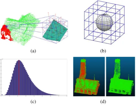
Once the buildings have been roughly identified the point set for each structure gets spatially sorted by regularly subdividing its axis-aligned bounding box. The length of the edgesaof the re-sulting cubes can be either specified manually if the noise level is known in advance or guessed automatically from a sparse dry-run of the following loop at random. For distortion removal, for each of the voxels the samples inside a3×3×3environment undergo a fast principal component analysis (PCA) to locally estimate the object surface. In order to decide if the current cube is eligible for noise elimination it must be tested efficiently whether it inter-sects with the approximated planar patch or not. For this purpose a sphere with the radius of half the voxel diagonalr = a
2 √
3 is constructed around its midpoint. When the estimated surface touches the sphere the Euclidean distances of the patch to the points of the cube are calculated and binned to form a histogram. Otherwise the algorithm continues with the next voxel. Since the 26-neighborhoods of adjacent kernels overlap it is guaranteed by the sampling theorem that the building points are continuously scanned inhibiting structural breaks. Using a sphere to determine whether the locally estimated surface is to be denoisied by a par-ticular voxel or not introduces a small chance that the cube incor-rectly accepts the planar patch even though it does not intersect with the element at all. However, since speed is crucial for any volume-based algorithm and the plane normal for the spherical collision test is already available from PCA as the Eigenvector with the smallest Eigenvalue of the underlying covariance matrix the accurate but computationally more expensive intersection test against any of the twelve voxel edges is abandoned in favor of the former.
Having the distance histograms for each voxel noise elimination consists in removing those points from the cube whose distances exceed the value of the class with the maximum sample count. This maximum will be unique if the noise is normally distributed and hence its causes, for instance bundle adjustment issues, do not expose a systematic error. In this case the histogram will follow a discrete version of theχ2distribution even though the
square root has been taken on the involved differences. Because the square root operation however is a monotonous function the basic profile of the histogram will remain intact. Figure 1 illus-trates the voxel-based noise removal.
3. BUILDING RECONSTRUCTION
(a) (b)
(c) (d)
Figure 1. Voxel-based noise removal (a) Surface approximation using PCA (b) Neighborhood and sphere around the kernel for the fast cell intersection test (c) Sample point-to-surface distance
histogram (d) Sample cloud showing the removed points in red
groups to form fac¸ade fragments of the same orientation. This is achieved by pair-wisely comparing the line directions of the cells within the local 8-neighborhood and the line direction of the cen-ter element against a fixed angular threshold. In case of match-ing directions the respective cells are added to the same cell set. When no more adjacent cells are left to be assigned a common re-gression line will be estimated through the point set of each cell group. The resulting linear fac¸ade fragments will be intersected if their endpoints are locally adjacent within the grid forming a closed two-dimensional building contour. Similarly, the rooftops get modeled by sorting the 3D points into a grid keeping the z coordinates this time. Cells outside the polygonal outline from fac¸ade detection get discarded, and regression is performed for each grid element obtaining plane segments. Roof cells are iden-tified by applying a smoothness threshold and get merged into the same labeled cell group if their normals roughly point into the same direction.
To derive the geometry of the housetops from the cell groups their topology needs to be computed. Following region growing to close gaps between the labeled cell clusters caused by roof instal-lations the grown cell sets are tested for connections by shifting a2×2window over the axis-aligned bounding box of the pro-jected area. If the window covers two or more different labels this will indicate a topological edge or node between adjacent cell groups respectively to be stored in a table. In a comparable fashion the topology between the roof and the building fac¸ades is analyzed. For this purpose the polygonal outline of the struc-ture obtained during wall surface reconstruction gets discretely scanned linearly or circularly around the building corners to ob-tain arrises.
Using the spatial relationship between the building surfaces the world coordinates of the roof elements are derived from the in-formation stored in the topological table which itself does not hold any positional information. The housetop is set up by fitting regression planes to the 3D points confined in the respective roof cell groups, and the fac¸ade planes get constructed by extruding the respective segments of the building contour perpendicularly to the xy plane. Having these geometric entities the intersection of adjacent pairs of roof planes or a roof plane with a nearby wall surface yields the geographic position and direction of the topo-logical edges, i.e. the roof ridge, arris and the outer edges of the
housetop. Since the resulting possibly skew lines will be infi-nite they need to be limited by the spatial representation of the topological nodes before they can form the skeleton of the build-ing to be modeled. Therefore the node coordinates are computed as the geometric center of the shortest connecting line among all combinations of pairs of lines derived from the topological edges, and the edge lines get adjusted accordingly. To complete the ini-tial reconstruction the missing ground surface is derived from the building contour, and its z value is set to the height estimate from the DTM mentioned before.
However, even though the described algorithm by design already supports certain segmented fac¸ade geometries it will fail on build-ings with larger discontinuities in particular when the roof is in-corporated. In this case inconsistencies between the topological entities and the intersection calculations occur and a restart of the modeling process is triggered for the affected object entirely in 3D which trades speed for correctness. Like for noise reduction the algorithm starts by regularly subdividing the bounding box of the point cloud of the respective building. Since the distortions have been already removed the voxel edges can be set to approxi-mately half the size previously used for the filter which allows to capture equivalent discontinuities. For each cube the local sur-face as sampled by the contained points is approximated with PCA. Plane segments in adjacent voxels whose normal vectors roughly point into the same direction are used to estimate a com-mon spatially infinite building surface. In order to limit the extent of the surfaces efficiently their spatial relationship would be ben-eficial. However, neither region growing nor the sampling tech-nique from initial reconstruction is applicable to 3D point sets to gain information on how the potentially adjacent areas are meant to be joined. Therefore, all combinations of triplets of infinite building surfaces get intersected. This results in a considerable set of vertices which can be condensed by dropping those points that are outside the bounding box of the building and those that exceed a user-defined distance to the closest point of the grid cells the three defining planes come from. The remaining ”good” ver-tices are analyzed for identical positions and consolidated yield-ing both world coordinates and topologicalk-nodes. Herekis the number of coinciding surfaces, and having values forkless than the real intersection count at a particular building corner in-evitably leads to more or less severe reconstruction errors. To minimize the error rate the input data should comprise of dense point clouds as they can be derived from high-resolution oblique images.
Once the set of vertices is final the topological edges connecting two points remain to be determined to obtain the building hull in-cluding any modeled discontinuities. This however is trivial since the necessary information will be an intermediate result when the infinite surface triplets get mutually intersected. Figure 2 illus-trates the volumetric reconstruction process.
4. ROOF OVERHANGS
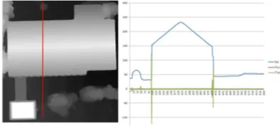
The resulting 2D shapes will be offset equally along the edge nor-mal vectors with subpixel accuracy exploiting the zero-crossings of the second-order directional derivative in the gradient direction of the height map (see figure 3). The reconstructed roof polygons of the respective building model then get extended accordingly.
(a) (b)
(c) (d)
Figure 2. Voxel-based building reconstruction (a) Grid cell planes (b) Vertices from intersecting all planes (c) Condensed vertices (d) Polygonal building hull with modeled discontinuities
Figure 3. Roof overhang estimation from the ortho-DSM
5. TEXTURE MAPPING
For realistic visualization the polygons of the reconstructed build-ings remain to be decorated. In a process called texture mapping the original oriented aerial images are projected onto the model surfaces since they congruently provide the necessary color infor-mation. Texture mapping assigns each point of a building poly-gon a normalized 2D position inside a bitmap pointing to the pixel which effectively provides the spectral intensities at that vertex. Any pixel of the interior zone of the face will then be automati-cally interpolated by the 3D render engine. Computing the tex-ture map involves finding the set of aerial images that pictex-ture a particular polygon best. Occlusions need to be bypassed using multiple source images if available, and radiometric differences on a model polygon must be corrected. Also, those parts of the chosen images that actually contribute to a face have to be com-pactly arranged and efficiently rendered to a single image called texture atlas. Creating a texture atlas is essential because render engines cannot efficiently handle hundreds or thousands of
high-resolution aerial bitmaps at once due to limitations on memory, I/O and hardware mappers on the graphics card.
To find the set of images that optimally colors a particular part of the building model the whole set of oriented photographs is analyzed per polygon. A unified resolution-based measure de-termines the priority of both the nadir and oblique color sources. This value is computed by initially projecting the vertex of the building polygon with the greatest distance to the current camera into the corresponding image. The four corners of the pixel that gets hit on the virtual sensor are ray-cast, and as a result the inter-section points with the polygon plane will span a convex quadri-lateral in world space. The quality index is the square root of the area of this quadrilateral, that is, the side length of a coexten-sive square at the same place, or, the worst-case ground sample distance (GSD) on the surface in terms of photogrammetry.
When the list of source bitmaps has been composed for a recon-structed surface and put in ascending order with respect to the GSD it will be passed to the visibility test to detect occlusions. This works by mapping the building polygon into the camera of the current image in world coordinates and discretely ray-tracing each pixel inside the ortho-DSM of the scene. Collisions with the DSM are kept in a run-length encoded (RLE) binary bitmap per texture patch per source image to save space. Particularly in highly overlapping oblique flight configurations the visibility data gets also involved in removing texture sources that do not provide any additional information. Thus, a graph for each pair of texture patch candidates(Ti, Tj), i 6= jthat picture a building surface is constructed from the binary bitmaps. This graph keeps the to-tal count of visible pixels for eachTiin its nodes and stores the non-commutative count of overlapping pixels in its edges. Both values describe the overlap ratio betweenTiandTj, and texture sources violating a user-defined percentage get discarded. More-over, the graph is analyzed to derive the coefficients for radiomet-ric adjustments between overlapping sources texturing the same building surface. This will produce homogeneous render results when occluded parts of a polygon are padded. To obtain the coef-ficients of the chosen linear correction model from (Fisher, 1992) the minimum spanning trees and hence disjoint sets of overlap-ping texture sources are computed among which the radiometry can be adapted (Kruskal, 1956). The resulting factors are added to the graph nodes to be applied when the texture atlas is being finalized.
Once the building faces have been assigned patches of one or more aerial images the actual color information is ready to be written to the texture atlas in two steps. During the placement stage a compact layout is obtained first, however, globally op-timizing the arrangement of polygonal pixel sets inside a rect-angular bitmap is known to be NP-hard. Therefore, as a local optimization running in polynomial time, new texture patches get placed inside the atlas one by one. To find the next free spot for the current patch Pi the vacant positions inside the destination bitmap are sequentially traversed. Once a free position has been found it will be attempted to pastePiin there allowing lossless rotations in steps of90◦to utilize the available space as efficiently as possible. If there is no overlap with any existing patch the at-las position and rotation angle forPiwill be stored in a dynamic list and the algorithm will proceed with the next patch. However, in casePicannot be pasted anywhere the destination bitmap will get resized horizontally and vertically to the next power of two of pixels as demanded by most graphics adapters.
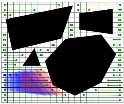
free spots will be accelerated by a block availability map (BAM). The BAM keeps track of unoccupied scanline segments inside the texture atlas. Also, a coarse 2D grid that effectively sorts the existing texture patches spatially limits the amount of previously arranged pixel sets aPihas to be tested against for overlaps on av-erage. Moreover, although a particular patch can only be placed after its predecessors without risking a collision and hence an in-herent data dependency will prevent the use of multi-threading at first sight, the exhaustive search nevertheless can be at least partially parallelized. This is achieved by running the overlap test, i.e. rotating the currentPiand testing it for a collision with any patch stored by the intersected 2D grid cells, concurrently for each BAM range (see figure 4). The final texture patch place-ment comprises of the first position inside the current scanline segment, and the other threads bail out as soon as the arrange-ment with the minimum horizontal coordinate within the range has been found. Thus, the multi-threaded search inside the BAM blocks will pay out primarily when the texture atlas fills up more and more. It will not have a significant effect on the first few placements which however can be expected to run fast anyway.
Figure 4. Sample four-threaded texture patch placement on BAM segments indicating free atlas spots (green). The leftmost blue position will be picked, and the red position collides with a
previously placed polygon (black).
In the render stage the color information from the respective aerial source images gets actually written to the designated places in-side the atlas bitmap. In case of the root image as of the overlap tree contributing most of the pixels to a building polygon no re-sampling is involved. However, if occlusions must be bridged subordinate images need to be warped to the shape of the root image. Also, the radiometric adjustment coefficients are applied now recursively, and untextured areas inside the atlas get interpo-lated by inverse distance weighting.
To correctly render the colored building models in a 3D viewer the 2D coordinates of the vertices inside the texture atlas are re-quired to be normalized by the atlas dimensions. Moreover, be-cause the texture patches have not been ortho-rectified and the perspective correction hard-coded in graphics processors applies to the viewer’s position only but not the world position of the root image distortions may be introduced during visualization (Low, 2002). The solution to this problem is to pre-scale the texture pix-els in the moment they get displayed. This is done by projecting the verticesviof each building face orthogonally onto the sensor plane of the respective root camera running through its center of
projectionCw, i.e. computing
di=|n((vi−Cw)·n)| (1)
wherediis the distance between the vertex and its projection in world space andndenotes the camera normal. During visual-ization the value ofdimust be multiplied with the texture coordi-nates assigned to the respective vertex, and the product undergoes the normal view-dependent perspective-correct interpolation by the raster unit. Before the color samples can be correctly retrieved from the texture atlas and displayed the interpolated product is di-vided by the now interpolated value ofdieffectively performing online rectification. Since the distancesdicannot by calculated online by the GPU because it lacks the camera orientation the values are added to the normalized texture coordinates forming texture coordinate triplets.
6. WINDOW CLASSIFICATION
In a last optional step the generated atlas bitmap can be passed to a commercial object-based image analysis (OBIA) tool executing a custom rule set to identify windows on the contained unrectified fac¸ade patches as described in (Frommholz et al., 2016). Fol-lowing segmentation and classification based on the brightness and contrast potential window objects are tested against geomet-ric constraints, conditionally grown, fused and morphologically filtered. The output polygons get vectorized and reintegrated into the previously reconstructed buildings by sparsely ray-tra-cing their vertices. The final model comprising 3D point co-ordinates, indexed polygon descriptions and texture information is stored in the open Alias/Wavefront OBJ format for visualiza-tion. Also, the building models are written as semantically anno-tated CityGML objects for GIS applications. The required sur-face types are implicitly deduced from the plane normals during reconstruction.
7. RESULTS
In a proof-of-concept the proposed method has been evaluated on images of the island of Heligoland/Germany taken by the DLR MACS HALE aerial camera (Brauchle et al., 2015). This de-vice comes with one nadir-looking and two oblique RGB sensors (4844 x 3212 pixels, 12 bits per component) pointing to the left and right at an angle of 36◦ to the vertical axis. An on-board GNSS receiver and IMU is available to assign each image the approximate camera position and rotation. Preprocessing trans-formed the 3478 input images into point clouds, DSMs and a DTM at a resolution of 5 cm per pixel.
From this data four buildings with discontinuities and roof over-hangs have been selected to be processed. Following noise re-moval which reduced the initial point cloud size per object from roughly 200 megabytes to 30 megabytes reconstruction with a MATLAB prototype implementing the the three-dimensional re-gression took about 90 seconds for each structure. As mentioned the software is not fully automatic yet but requires some data-dependent input parameter to be estimated in advance.
deviation of 0.29 m and a mean positional deviation of 0.36 m was found. This is approximately half the distance obtained with-out noise removal which, using the same processing parameters, initially yielded a median deviation of 0.53 m. The roofs includ-ing their overhangs were visually compared to an ortho-DSM ob-tained from the nadir images only since no ground measurements were available and the operating experience on the photogram-metric workflow for the vertical views is likely to be less error-prone than the all-embracing oblique process. Except for point noise no significant discrepancies have been found, and the over-hang estimation always was within twice the DSM resolution, i.e. 10 cm.
Figure 5. Comparison of the building outlines without roof overhangs (transparent green) and the cadastral map (red)
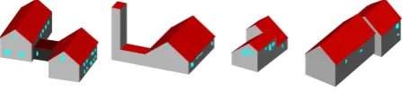
Figure 6. Textured buildings with discontinuities, roof overhangs
Figure 7. Buildings with windows as CityGML objects
Texture mapping on the four buildings exposed more than 100 image candidates for each polygon due to the highly overlapping flight pattern. In the end a maximum of 15 bitmaps has been kept after the visibility test and redundancy removal. The worst-case GSD on the polygons ranges from 5 to 11 cm depending on the surface slope and building orientation on the ground
rel-ative to the camera. The l3tex+ software written in C++ needed 7:42 minutes for the 73 polygons in total on a 2012 server. A great share was absorbed by the I/O-intensive image validation and the visibility test taking over three minutes each. The time required for texture placement alone reduced from four to about two seconds when the partially parallel algorithm was enabled us-ing eight threads. Because these values are too small to allow an assessment of the change in performance due to the limited quan-tity of structures texture mapping was repeated on a larger data set comprising 75 buildings which were extracted with the initial re-construction algorithm only. For its 632 faces texture placement took 3:29 minutes on a single CPU core and 51 seconds using eight threads of execution concurrently. Figure 6 depicts the four colored sample buildings. Visualization glitches can be spotted particularly on the fac¸ades because the reconstruction does not match reality and due to image orientation inaccuracies.
Window classification on the only texture atlas using OBIA is automatic and occupied two CPU cores on the eCognition work-station for about two minutes for a bitmap of 2048 x 1024 pixels. No new accuracy analysis has been performed since complete-ness and correctcomplete-ness numbers for the Heligoland data set have been already presented in the paper cited above. Figure 7 illus-trates the semantically annotated CityGML objects of the four buildings.
8. CONCLUSION
In this paper a reconstruction approach for buildings with dis-continuities and roof overhangs has been presented that relies on aerial images acquired by a decent oblique camera system only. The dense point clouds on the wall surfaces derived from the tilted views enable voxel-based algorithms to accurately model structural breaks. Also, the input data has been successfully uti-lized for automatic high-quality texture mapping and subsequent window extraction. In this context a partially parallel placement algorithm has been developed which in practice achieves a con-siderable speed-up for a problem with inherent data dependen-cies.
However, even though the proposed method performs well on an exceptional data set scaling the involved algorithms to larger ar-eas still remains to be evaluated. In particular when a high image overlap is not feasible and gaps have to be bridged by the voxel-based algorithm the probability for reconstruction errors will in-crease. This issue is currently under examination, and a first so-lution based on point cloud extrapolation has shown promising results.
Moreover, difficulties persist to obtain appropriate three-dimen-sional ground truth beyond the cadastral maps for a thorough ac-curacy analysis of the developed algorithms. Undoubtedly, hav-ing a standardized multi-purpose artificial test scene suitable for both reconstruction and texture mapping would be very benefi-cial. Because aspects like resolution flexibility, illumination mod-els and reproducibility must be addressed consistently first ob-taining a basically error-free reference will remain an ambitious task.
ACKNOWLEDGMENTS
REFERENCES
Brauchle, J., Hein, D. and Berger, R., 2015. Detailed and highly accurate 3D models of high mountain areas by the MACS - Hi-malaya aerial camera platform.Int. Archives of Photogrammetry, Remote Sensing and Spatial Information Sciences40, pp. 1129– 1136.
Fischler, M. A. and Bolles, R. C., 1981. Random sample con-sensus: A paradigm for model fitting with applications to im-age analysis and automated cartography. Communications of the ACM24(6), pp. 381–395.
Fisher, Y., 1992. Fractal image compression. SIGGRAPH’92 Course Notes.
Frommholz, D., Linkiewicz, M. and Poznanska, A. M., 2016. Inlining 3D reconstruction, multi-source texture mapping and se-mantic analysis using oblique aerial imagery. ISPRS - Interna-tional Archives of the Photogrammetry, Remote Sensing and Spa-tial Information SciencesXLI-B3, pp. 605–612.
Frueh, C., Sammon, R. and Zakhor, A., 2004. Automated tex-ture mapping of 3D city models with oblique aerial imagery.
3D Data Processing, Visualization and Transmission Proceed-ingspp. 396–403.
Haala, N., Rothermel, M. and Cavegn, S., 2015. Extracting 3D urban models from oblique aerial images. Joint Urban Remote Sensing Event (JURSE) 2015 Proceedings38, pp. 1 – 4.
Hirschm¨uller, H., 2008. Stereo processing by semi-global match-ing and mutual information.IEEE Transactions on Pattern Anal-ysis and Machine Intelligence30(2), pp. 328–341.
Kruskal, J., 1956. On the shortest spanning subtree and the trav-eling salesman problem. Proceedings of the American Mathe-matical Society7, pp. 48–50.
Low, K.-L., 2002. Perspective-correct interpolation. Technical writing, Department of Computer Science, University of North Carolina at Chapel Hill.
Mayer, S., 2004. Automatisierte Objekterkennung zur Inter-pretation hochaufl¨osender Bilddaten in der Erdfernerkundung. PhD thesis, Humboldt-Universit¨at zu Berlin, Mathematisch-Naturwissenschaftliche Fakult¨at II.
Panday, U. S. and Gerke, M., 2011. Fitting of parametric building models to oblique aerial images. Int. Archives of Photogram-metry, Remote Sensing and Spatial Information Sciences 38, pp. 233–238.
Remondino, F. and Gehrke, M., 2015. Oblique aerial imagery -A review.Photogrammetric Week ’1512, pp. 75–81.
Rupnik, E., Nex, F. and Remondino, F., 2014. Oblique multi-camera systems - orientation and dense matching issues. Int. Archives of Photogrammetry, Remote Sensing and Spatial Infor-mation Sciences40 (3/W1), pp. 107–114.
Smith, M., Hamruni, A. M. and Jamieson, A., 2009. 3-D Ur-ban Modelling using Airborne Oblique and Vertical Imagery.
Archives of the ISPRS 38-1-4-7/W5.
Stilla, U., Kolecki, J. and Hoegner, L., 2009. Texture mapping of 3D building models with oblique direct geo-referenced airborne IR image sequences.Archives of the ISPRS 38-1-4-7/W5.
Sun, Y., Shahzad, M. and Zhu, X., 2016. First prismatic building model reconstruction from TOMOSAR point clouds. ISPRS -International Archives of the Photogrammetry, Remote Sensing and Spatial Information SciencesXLI-B3, pp. 381–386.