1) Mahasiswa Teknik Elektro UNDIP
IMPLEMENTATION BLUETOOTH LOW ENERGY ON
THE MEDICAL SUPPORTING DEVICE
Fakhri1) , Darjat2)
Jurusan Teknik Elektro, Fakultas Teknik, Universitas Diponegoro Jln. Prof. Sudharto, Tembalang, Semarang, Indonesia.
ABSTRACT
Non-compliance from a patient is a serious problem, with a big consequence in case of health and costs. ECCT B.V. tries to develop some supporting devices expected to help patients to report their compliance. One of these supporting devices is a dispenser. These devices record data a bout time a nd other clinically relevant information. The electronic circuit also contains RFID technology, it is possible for Near Field Communication (NFC) enabled mobile telephone or a NFC rea der to take the stored data.
If we compare Bluetooth with NFC, Bluetooth has an advantage in range, Bluetooth has wider range than NFC. When the dispenser starts using BLE, there is no need for us to make the dispenser close to BLE enabled mobile phone or reader, we can separate it in some distance.
The antenna design was done by using CST Microwave Studio 2009, provided by Fontys Hogescholen. In this project, author uses printed Inverted F Antenna as the antenna. Inverted F Antenna has some advantages and also fulfills the requirements for transmitting and receiving data. From the simulation we can find out there is 7 parameters affected on the antenna performance. Length is one of the parameters affected to the antenna resonant frequency.
From the measurement result, Bluetooth Low Energy for “Firefly” can reach 10 meters range
and can stand for 3 years using coin cell battery. In the future, the “Firefly” should be developed in
thinner PCB, 0.5mm PCB thickness, because dispenser requires 0.5 mm PCB thickness for the perfect final product.
Keywords: Near Field Communication, Bluetooth Low Energy, and Antenna.
I. INTRODUCTION
Due to of a compliance, ECCT B.V. tries to develop some medical supporting devices that expected to help the patient to report their compliance. This expected to have effective reminders, improve patient’s education, and help the doctor to make a decision at the right time. These supporting devices consist of smart blister and dispenser.
At the moment, either smart blister or
dispenser uses a Near Field
Communication (NFC) system. By using a NFC enabled mobile telephone, we can get all of recorded data from the devices. It is required to make close distance between the devices to the phone. Now, we try to develop the devices using Bluetooth Low Energy (BLE) system
communication, if we use the BLE system, there is no need for us to make close between the devices with the phone, we can separate it in some distance. This assignment focuses on dispenser devices.
II. THE ASSIGNMENT
1) Mahasiswa Teknik Elektro UNDIP IFA has some requirement that need to be fulfilled. To fulfill the requirements, the Antenna Design will be simulated using CST Microwave Studio 2009. Antenna will be printed in the PCB, expected reduce the cost.
Initial Situation
To improve compliance for patients, an electronic device has to be developed, which is used to store information about the medication and about the patient’s medicine education. ECCT develops a bottle called dispenser that connected to “Firefly”.
“Firefly” is a design contains wireless communicator for collecting and transmitting data information, gathered from the dispenser. The “Firefly” consists of two parts, the white part and the blue part. The white part is a one-time use part when a new bottle has been taken due to hygienic reasons and/or when the medication type changes. It is easy to release the blue part from the white part and put on a new white part. The blue part is where the electronics and battery take place and white part is where the blue part mounted.
BLE consumes only a fraction of the power classic Bluetooth, it consumes between ½ and 1/100 the power of classic Bluetooth technology.
III. BLUETOOTH LOW ENERGY ANALYSIS
Introduction to Bluetooth
Condition when two Bluetooth devices are connected each other is called pairing. Connections between Bluetooth enabled devices to communicate wirelessly through short range, and ad hoc networks known as piconets [3]. In a typical Piconet, only one of the devices work as a master,
the rest act as a slave. Each of piconets can communicate up to seven other devices and each device is belong to several piconets, it means Bluetooth connections is almost unlimited.
The commonly used Bluetooth is class 2, it has a range of 10 meters or 30 feet, it consumes 2.5 mW of power, Bluetooth is designed to have low power consumption. Bluetooth technology does not require a Line of Sight connection, it can penetrate a solid objects.
Bluetooth technology works on 2.402 – 2.480GHz the Industrial, Scientific, and Medical (ISM) band, this band is free licensed, unfortunately, it can be distorted by other radio link. Bluetooth uses a spread spectrum, adaptive frequency hopping (AFH), and full duplex signal.
AFH means the whole frequency spectrum is divided into 79 channels, 1MHz for each of them. The aim of AFH is to reduce the interference between wireless technologies sharing and good performance when other technologies are being used in the ISM band.
Introduction to Bluetooth Low Energy
1) Mahasiswa Teknik Elektro UNDIP Bluetooth Low Energy (BLE) technology works on the same frequency range (2.402 – 2.480 GHz) just like classic Bluetooth, one of the differences is the amount of channel. If classic Bluetooth has 79 channels 1MHz each of them, BLE has 40 channels 2MHz each of them.
There is a significant amount of intelligence in BLE’s controller, that allows to sleep in a longer periods, and be woken up by the controller if only needs to perform an action.
Due to the implementation of low power consumption, it makes a change in the Physical Layer and packet format in order to reduce the power. This is why Classic Bluetooth cannot communicate with BLE directly without dual mode helps.
Dual Mode Bluetooth Low Energy is not optimized for Ultra Low Power (ULP) operation like single mode because the requirement to operate Classic Bluetooth and BLE functions. Bluetooth Low Energy (BLE) Technology features [4]:
1. Ultra low peak (20 mA), average (15 μA), and idle mode power consumption (0.9 µA). 2. Ability to run for years on
standard coin cell batteries 3. Low cost, under $3. 4. Multi vendor operability 5. Enhanced range, over 100 m. Bluetooth Low Energy and Classic Bluetooth Comparison
BLE employ only three “advertising” channels to search for other device or promote its presence to device that might be looking to make a connection. For classic Bluetooth, it uses 32 channels.
There are three characteristics of BLE technology to achieve its ultra low power performance: maximized standby time, fast connection, and low peak transmit/receive power.
BLE can complete a connection (scan, link, and send data) just in 3ms. For classic Bluetooth, the same connection might be needed hundreds of milliseconds. We know that, more time on air requires more energy from battery.
Classic Bluetooth has a vary data rate, depends on version, which is mostly higher than 1 Mbps. BLE can transmit 1 Mbps. As well as the very high physical bit rate, the packet overhead has to be considered. BLE will use much less energy to transmit the same quantity application.
For modulation scheme, either BLE or classic Bluetooth use a GFSK (Gaussian Frequency Shift Keying) modulation. However, BLE uses a modulation index 0.5, compared classic Bluetooth 0.35. An index of 0.5 is closed to a GMSK (Gaussian Minimum Shift Keying) scheme and lowers the radio power requirements (the reasons are complex and beyond the scope). The advantages of the lower modulation index are increased range and enhanced robustness.
In the acknowledgement scheme, when a packets are being transmitted; classic Bluetooth performs fast acknowledgement. BLE performs lazy acknowledgement.
1) Mahasiswa Teknik Elektro UNDIP BLE has some features: slave latency; this parameter gives the slave (peripheral) device option to skip a number of connection events. This gives the peripheral device some flexibility, if it does not have any data to send, it can choose to skip connection events and stay sleep, that provides some power saving. The decision is up to the peripheral device. Bonding; a feature allows the two devices to quickly re-establish encryption and authentication after re-connecting without going through the full pairing process every time that they connect, as long as they store the long term key information.
IV. ANTENNA DESIGN IMPLEMENTATION
Antenna Fundamental
A wavelength is the required antenna length, which will be implemented in the design. Relation between frequency and wavelength by the following equation:
cf where;
f = frequency in Hertz (Hz) = wavelength in meters (m) c = speed of light (3.108 m/s)
According to this equation, the higher the frequency, the shorter the wavelength, and the smaller the antenna [6]
Impedance
Impedance (symbol ZL), is a
measurement of the overall opposition of a circuit to current. Inductive and capacitive elements, other antennas, component on circuit boards, and even the user of the device will effect on the antenna’s frequency.
VSWR
A measurement how good the antenna match to source impedance, typically 50 ohms, called the Voltage Standing Wave Ratio (VSWR). It is calculated by measuring the voltage wave that is headed toward the load versus the voltage wave that is reflected back from the load [6].
Mismatching of the antenna is one of the biggest factors that reduce the total RF link budget. To avoid this, it is recommended to add matching network so that the antenna can always be matched. If the antenna is matched, then zero ohm resistors can be added into the matching network.
Bandwidth
A frequency range over which the antenna designed to operate correctly is called Bandwidth. In some applications, a much wider bandwidth is required. The less reflected signal is, the narrower is the bandwidth. In practice, bandwidth is typically determined by measuring a characteristic such as VSWR or radiated power over the frequency range of interest.
The Return Loss of a line is a ratio of the power reflected back from the line to the power transmitted into the line. For maximum power transfer, the return loss should be as small as possible.
Near – Far Field
1) Mahasiswa Teknik Elektro UNDIP Radiation Pattern
The Radiation Pattern is a graphical illustration that presents the distribution and the direction of the radio frequency energy into free space by the antenna. It is commonly presented in the three-dimensional Efficiency, Directivity, and Gain Efficiency is one of the most important antenna parameters. Antenna efficiency is the ratio how much power delivered to the antenna instead of lost as a heat on the antenna’s structure or
Directivity measures how much greater an antenna’s peak radiated power density is in a particular direction than a reference radiation pattern [6].
Gain is the directivity of the antenna reduced by the losses on the antenna, such as dielectric, resistance, and VSWR [6].
Transmission Line
A transmission line is a medium where RF energy is transferred from one place to another with minimum loss. This is important because it can effectively contribute to the antenna’s length, changing its resonant frequency. That is why the trace that goes to the antenna is important.
Inverted F Antenna
Inverted F Antenna (IFA) was chosen for this device. The IFA is effectively quarter-wavelength 4 monopole antenna that bent into L-shape. The shorter side is connected to the earth and the longer side is left open-circuit at the end [23].
This is very popular because of its size since one antenna element is one 4 wavelength and the GND plane acts as the other 4 wavelength, which
produces an effective 2 antenna. The feed point, which is the input/output connection, located between the shorter side and the longer side, and connected to the L-shape that fit to 50.
In the PCB version, the antenna is printed on the top layer and a ground plane is placed near the antenna on the top layer [23]. It is required that there is no a ground plane underneath the antenna.
Table 1. Effect of different design parameters [17]
Parameters Effect
Height Control bandwidth Width Control impedance
matching Length
Increase inductance of the antenna and determine resonance frequency
Width of short strip
Affect on the anti resonance and increase bandwidth
Feed position from short strip
Affect on the
resonance frequency and bandwidth Simulation
In the design, we also need to modeled a metal objects, because it will have an effect to the antenna, causing detuning. We recommend to put the metal objects as far as possible from the antenna. The dielectric material will also have an effect to the antenna, by lowering the resonant frequency, but this can be solved by reducing the length of the antenna.
1) Mahasiswa Teknik Elektro UNDIP loss, we can calculate the VSWR, and the result is 1.04:1.
We pay some attention on the -6dB Bandwidth. -6dB Bandwidth is defined as the frequency band at 75% power is transferred and 25% is reflected back. We have a 0.2203 GHz as a result for -6dB Bandwidth.
The return loss for the antenna simulation is -33.13. From the VSWR table, we can see that the power transferred is 99.962%; and for reflection power is 0.038%.
Antenna Matching
A mismatch happens when some of the power that sent to the antenna will be reflected back into the load or lost as heat. Unfortunately, there is a miscommunication when ordering PCB, as a result, author gets 1.6 mm thickness of PCB, this difference will also effect on the antenna’s frequency. The environment around the antenna has a great impact of the performance. The impedance is on 31.5 Ω + j 3.58 Ω. By adding 0 Ω resistor, we can get the measurement impedance is on 31.7 Ω + j 496.67 mΩ. This adding component can be found by using Smith Chart manually by following the curve on the chart to the center of the chart (50 Ω), or we can use Smith Chart Software.
To find the correct resonant frequency, we need to reduce the antenna’s length, because the antenna’s resonant frequency at the original length was on 2.1 GHz. The required frequency range is on 2.402 GHz to 2.480 GHz, so we need to shift the resonant frequency to the right. As a result, we reduce the antenna’s length 2.5 mm and we can see the resonant frequency is on 2.431 GHz. It is suggested to reduce the
antenna’s length step by step. The return loss value is -13.4 dB. Another important parameter for antenna measurement is VSWR the value is 1.59.
We can see from VSWR table, 95.5% of the powers are transferred and only 4.5% powers are reflected back. There is a difference between simulation and measurement, this difference happens because the difference of PCB thickness. In simulation we use 0.5 mm PCB thickness, in measurement we use 1.6 mm PCB thickness. Due to PCB thickness differences, we need to cut the antenna’s length, so it will be different from the simulation, and it will change the performance.
V. DEVICE MEASUREMENT
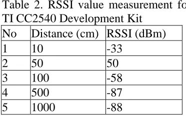
Received Signal Strength Indication Received Signal Strength Indication (RSSI) is an indication of the power level being received by the antenna. To get the actual RSSI value, we can use BTool PC software, this software is provided by Texas Instruments (TI). Table 2. RSSI value measurement for TI CC2540 Development Kit
No Distance (cm) RSSI (dBm)
1 10 -33
2 50 50
3 100 -58
4 500 -87
5 1000 -88
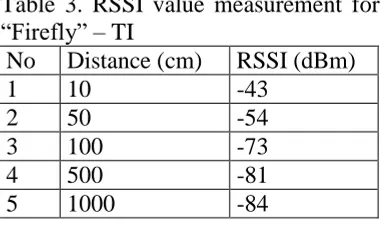
1) Mahasiswa Teknik Elektro UNDIP Table 3. RSSI value measurement for “Firefly” – TI
No Distance (cm) RSSI (dBm)
1 10 -43
2 50 -54
3 100 -73
4 500 -81
5 1000 -84
In this measurement, device under test will act as a slave, while TI device will act as the master. From the table above, we can see that on 10 meters distance, “Firefly” still in a good form, because sensitivity for BLE is –87 dBm up to -93 dBm.
Power Consumption
Bluetooth Low Energy was designed with one aim, allowing devices to perform with coin-cell battery for several months or several years. Power Consumption measurement was tested inside the final casing that is going to be used, measurement consists of standby mode and discoverable mode. In this measurement, we will compare between TI development kit and “Firefly” PCB.
Table 4. Standby mode measurement No. Devices
Power consumption
(µA)
1. CC2540 DK 1.0
2. “Firefly” 1.2
When we measure discoverable mode, we also need USB Dongle and BTool PC Software, those two things are needed to form a connection between master (USB Dongle) and slave (“Firefly”). When we press the button, to make slave in the discoverable mode, the advertisement and scan response will pop-up in BTool window.
Table 5. Discoverable mode measurement
No Distance (cm)
Power Consumption (mA)
CC2540 DK
“Firefly”
1. 10 2.57 2.54
2. 50 2.85 2.83
3. 100 2.97 2.91
4. 500 3.37 3.29
5. 1000 3.26 3.4
From the result, we can see not that much difference between CC2540 Development Kit and “Firefly”; the difference is very small.
VI. CONCLUSIONS AND RECOMMENDATION
From the discussion above, the following conclusions can be drawn:
1. There are 7 parameters related to the antenna’s performance: height, width, length, width of short strip, PCB thickness, relative dielectric PCB, and working environment.
2. The length can control antenna’s resonant frequency. 3. The advantage of using CST
Microwave Studio is we can set the antenna match to 50. 4. From the measurement result,
“Firefly” can reach more than the required 10 meters range. 5. 95.5% of the power received by
the antenna will transferred to the receiver and the reflection power is around 4.5%.
Some recommendations can be given for further application in the future as follow:
1) Mahasiswa Teknik Elektro UNDIP 2. The “Firefly” should be
developed in thinner PCB, 0.5mm PCB thick. Because dispenser requires 0.5 mm PCB thick for the perfect final product.
3. The reflection power can be minimized re-matching the antenna.
Literature References
[1] Samosuyev, Vadym,
“Bluetooth Low Energy Compared to Zigbee and Bluetooth Classic”, Mikkeli University of Applied Sciences, May 2010.
[2] Hopper, Justin and Paul True,
“Understanding Antenna
Specifications And Operation”, The RF & Microwave Solution Update. [3] Geboers, Jos, “The “Firefly””, ECCT B.V., Eindhoven, The Netherlands, 2011.
[4] Bluetooth Special Interest Group, “Why is low energy so efficient?”.
[5] Texas Instrument Application Note AN058
[6] Texas Instrument CC2540 Datasheet
[7 Daud, Muhyin, “Prototyping and Measuring Wireless Sensor Network Antenna”, Fontys Hogescholen, Eindhoven, The Netherlands, 2010.
[8] Liu, Duixian and Brian Gaucher, “The Inverted-F Antenna Height Effects on Bandwidth”, Yorktown Heights, NY.
[9] Kamath, Sandeep, “Measuring Bluetooth Low Energy Power Consumption”, Texas Instruments Application Note AN092, 2010.
[10] Application Note, “2.4GHz Inverted-F and Meander Line Antennas”, Cambridge Science Park, May, 2007.
[11] Mathiue, Sebastien, “Bluetooth Antenna Design”, National
Semiconductor Application Note 1811, March, 2008.
[12] Texas Instrument, TI Low Power RF, Designer’s Guide LPRF. [13] Ember Corporation, “Designing with an Inverted-F PCB Antenna”, Boston, 2008.
[14] Bluetooth Low Energy Wireless Technology Backgrounder. Nordic Semiconductor. Version 4.
RESUME
Fakhri was born in Semarang 9 July 1987. Graduate from SDN Sompok Elementary School on 1999, graduate from SLTPN 3 Junior High School on 2002, and graduate from SMUN 1 Senior High School on 2005. From 2005, he was studied in electrical engineering of Diponegoro University, with Electronics and Telecommunication as his minor.
Approved by, Academic Supervisor,
![Table 1. Effect of different design parameters [17]](https://thumb-ap.123doks.com/thumbv2/123dok/2201122.1224246/5.595.308.511.288.500/table-effect-different-design-parameters.webp)