Technische Universit¨at Dresden, DE-01062 Dresden, Germany a
Institute of Photogrammetry and Remote Sensing - (david.mader, robert.blaskow, patrick.westfeld)@tu-dresden.de http://www.tu-dresden.de/ipf/photo
b
Institute of Construction Management - [email protected] http://www.tu-dresden.de/biwibb
Commission THS11 Unmanned Aerial Systems: The Roadmap from Research to Applications
KEY WORDS:Unmanned aerial vehicle, 3D point cloud, LIDAR, thermal infrared camera, near infrared camera, RGB camera, building inspection
ABSTRACT:
Conventional building inspection of bridges, dams or large constructions in general is rather time consuming and often cost expensive due to traffic closures and the need of special heavy vehicles such as under-bridge inspection units or other large lifting platforms. In consideration that, an unmanned aerial vehicle (UAV) will be more reliable and efficient as well as less expensive and simpler to operate. The utilisation of UAVs as an assisting tool in building inspections is obviously. Furthermore, light-weight special sensors such as infrared and thermal cameras as well as laser scanner are available and predestined for usage on unmanned aircraft systems. Such a flexible low-cost system is realized in the ADFEX project with the goal of time-efficient object exploration, monitoring and damage detection. For this purpose, a fleet of UAVs, equipped with several sensors for navigation, obstacle avoidance and 3D object-data acquisition, has been developed and constructed. This contribution deals with the potential of UAV-based data in building inspection. Therefore, an overview of the ADFEX project, sensor specifications and requirements of building inspections in general are given. On the basis of results achieved in practical studies, the applicability and potential of the UAV system in building inspection will be presented and discussed.
1. INTRODUCTION
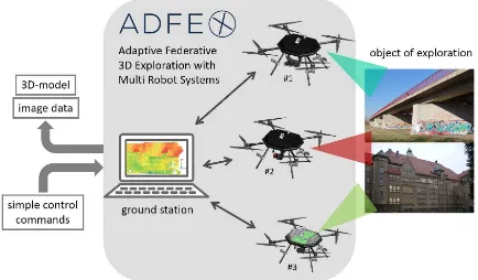
Conventional building inspection requires special heavy vehicles, is time consuming and cost expensive. Due to the high number of buildings, which need rehabilitation measures (Radke, 2014), an effective usage of limited resources, such as time and equip-ment, is important. This requires a highly up-to-date and effec-tive monitoring system for all important constructions of public life. For carrying out the monitoring tasks, a flexible and valu-able tool such as UAVs with special sensors can be very valuvalu-able. There are many investigations for using light-weight sensors on unmanned aircraft. Mainly RGB cameras are mounted on UAVs. Such an digital image-based building inspection and monitoring is shown in (Eschmann et al., 2012) by using a micro aerial ve-hicle and a high resolution digital camera. The results were a digital fac¸ade reconstruction based on image mosaic and auto-matically detected cracks. Morgenthal and Hallermann (2014) discuss the flight properties of UAVs and the resulting influenc-ing factors on the image quality. The authors in (Roca et al., 2014) utilized a combination of a light-weight laser scanner and an UAV for generating 3D point clouds for building assessment. An application for the combination of an UAV and a thermal cam-era is presented in (Lag¨uela et al., 2014). There, thermal data of hard-to-access areas such as higher fac¸ades and roofs was cap-tured to complete data from a handheld camera on the ground. The systems as stated above normally consist of one UAV with a special sensor, which covers a specific application. However, a wide variety of damage types, which are not detectable with one kind of sensor, occur on buildings. For this purpose, an adaptive low-cost system (Figure 1) consisting of three flying robots and a ground station was realized in the ADFEX project (Adaptive
Fed-∗Corresponding author
Figure 1: System design of ADFEX project. The capturing sys-tem consists of three UAVs equipped with special sensors and a ground station.
(a) (b) (c) (d)
Figure 2: (a) ADFEX copter Goliath Coax 8 from CADMIC. (b) Laser scanning range finder Hokuyo UTM-30LX-EW (Hokuyo, 2014). (c) High-resolution RGB camera AVT Prosilica GT3300C. (d) Camera bar including a RGB-, near infrared and thermal camera.
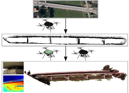
Figure 3: Scenario from an unknown area or building (top) via the first exploration with a laser scanning range finder mounted on an UAV (mid) to the fully explored building (bottom). Results of the exploration may be dense point clouds and detail images for damage detection.
in a provided map. Firstly the unknown area will be explored by UAV #1 equipped with a laser scanning range finder. The re-sulting geo-referenced rough 3D point cloud is well suited for the following mission planning by the user and in addition for an obstacle map. Subsequently, the data acquisition with the RGB, near infrared and thermal camera mounted on UAV #2 and UAV #3 will be carried out. By processing this data, the generation of dense and accurate 3D point clouds with multispectral attributes, the visual inspection based on geo-referenced images and the cre-ation of a map of damages is possible. Further informcre-ation can be found on the websitehttp://www.adfex.eu/.
This contribution shows the development and construction of an UAV based tool for building inspection exemplary for German in-dustrial standards. The first part deals with the utilized platform and sensors, the requirements of building inspection, as well as a short excursion into the calibration and sensor alignment. After-wards, it will be focussed on practical studies carried out and the placement of the developed system in building inspection tasks. Finally, the paper will finish with a conclusion and proposals for the next steps in future work.
2. REQUIREMENT PROFILE OF BUILDING INSPECTION
Within the framework of public service, civil engineering struc-tures like roads and ways are obliged to inspect periodically. The key components of the road building management are the security and the preservation of the serviceability. Special attention needs to be paid for road bridges. The bridge monitoring includes the detection, localization and rating of damages and defects with re-gard to structural stability, traffic safety and durability. After
de-termining the cause of damage, suitable rehabilitation measures have to be provided. In Germany, the procedure and amount of bridge monitoring is regulated by the German industry standard (DIN1076, 1999) complemented by the directive (BASt, 2007). It establish rules for planning of conservation measures, consis-tent acquisition and evaluation of inspection results as well as for carrying out economic feasibility studies. In addition, build-ings have to be inspected in general even if they are excepted from inspection and monitoring obligation by law. Inspections or maintenance at regular intervals and rehabilitation measures at an early stage ensure the fulfilment or a significant extension of the intended economic life of engineering works (Figure 4).
Figure 4: Maintenance of civil engineering works based on (Fechner, 2002) and (DIN31051, 2003).
Sensor CMOS CMOS uncooled microbolometer
Resolution 2048×2048 px 2048×1088 px 640×512 px
Pixel size 5.5 µm 5.5 µm 17 µm
Frame rate 26.3 Hz 49.5 Hz 30 Hz
Spectral properties ∼300 nm to 750 nm ∼830 nm to 1000 nm 7.5 µm to 13 µm
Lens mount/focal length C-mount C-mount fixed lens with 13 mm
Dimensions 60.5 mm×29 mm×29 mm 60.5 mm×29 mm×29 mm 106 mm×40 mm×43 mm
Weight 80 g 80 g 200 g
Table 1: Sensors of multispectral camera bar mounted on UAV # 3
3. INSPECTION SYSTEM
3.1 Unmanned Aerial Vehicle - basic equipment
The three flying robots are identical in construction. The CAD-MIC Goliath Coax 8 frame has four cantilever arms each with two coaxial mounted rotors (Figure 2a). The basic sensors configu-ration of each robot includes a single frequency GNSS-receiver u-blox LEA-6T, an ADIS16407 IMU module and two cameras with fisheye lens, which are oriented upwards and downwards for determination of the UAV’s position and orientation by using a visual SLAM navigation filter (Klix et al., 2014). Additionally, there are ultra-sonic sensors integrated to detect obstacles up to a distance of about 6 m arround the octocopter. Furthermore, all UAVs have additional special sensors for special tasks or appli-cations.
3.2 Special Sensor UAV #1
The first UAV is equipped with the low-cost 2D laser scanning range finder (LSRF) Hokuyo UTM-30LX-EW (Figure 2b), which works according to the time-of-flight principle and measures dis-tances in a range of 0.1 m up to 30 m with an accurracy given by the manufacturer of 30 mm to 50 mm . The LSRF captures 1080 distances in a plane during 1/40 s with an angular resolution of 0.25◦resulting in a field of view of 270◦. Important
prop-erties are the low weight of 210 g and the compact size (62 mm ×62 mm×87.5 mm), which predestines the LSRF for using on UAVs.
3.3 Special Sensor UAV #2
The RGB camera Prosilica GT3300C from Allied Vision Tech-nologies (Figure 2c) is equipped with a 3296×2472 px CCD-sensor and a pixel size of 5.5 µm. With14.7images per sec-ond, high-resolution images in a sufficient frame rate are guar-anteed. A F-mount camera bayonet allows a flexible application concerned choice of the lens. The dimension of the camera body with 121 mm×59.7 mm×59.7 mm and a weight of 314 g is well suited for use on the ADFEX-copter.
3.4 Special Sensors UAV #3
The multispectral camera system (Figure 2d) consists of the RGB camera Mako G-419C, the near infrared camera Mako G-223NIR and the thermal camera FLIR A65, all fixed rigidly on a bar. All cameras have a compact size and a low weight, whereby the in-tegration of the camera bar does not present a problem. The de-tailed specifications of the sensors are given in Table 1.
4. CALIBRATION AND ORIENTATION
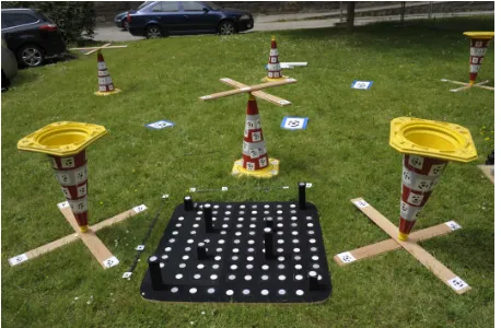
A sensor calibration and alignment of the entire system is dispensable for high-quality results. The calibration strategy in-cludes the determination of lever arm and boresight angles be-tween the sensor coordinate system (specified itself) and the plat-form coordinate system (given by the IMU) as well as the interior sensor parameters. In detail, there are the focal length, principal point and lens distortion for cameras as well as distance and an-gle correction for LSRF. An integrated self-calibration strategy was developed for a simultaneously estimation of all unknown parameters to guarantee a correct calculation with different obser-vation types (distances, angles, image point measurements with different sensors). For this purpose, an adaptive fully integrated and modularly structured bundle adjustment was implemented (Mader et al., 2014). A variance component estimation ensures an optimal weighting of the observation groups and additional restrictions (Koch, 1999). This approach was extended with
ge-Figure 5: Calibration field for self-calibration approach with cones and thermal markers as reference targets for laser scanner and multispectral image point measurements.
(a) (b)
(c) (d)
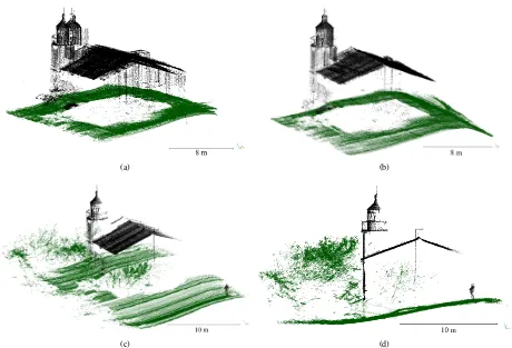
Figure 6: 3D point cloud of the lighthouse on basis of data from laser scanning range finder mounted on an UAV. (a) Unaligned point cloud with large lateral discrepancies. (b) Aligned point cloud. (c) The separate strips (in this case strip 2) shows the lighthouse with good geometries. (d) A side view of the complete strip 2.
5. PRACTICAL STUDIES
The focus of this work will be the potential and placement of UAV-sensor-systems in building inspection. For this purpose, practical studies were done and will be shown in this section.
5.1 Obstacle map and mission planning based on a rough point cloud
For evaluating the potential of the combination of light-weight LSRF and UAV using a single-frequency GNSS, the following aspects will be interesting: (1) precision of the relative position of neighbouring strips, (2) the quality of the point cloud in com-parison to reference data and (3) the accuracy of the absolute geo-referenced 3D point coordinates. The first two aspects were eval-uated by practical studies. The accuracy of the absolute position was not investigated and should correspond to most manufacturer specifications with usually 2 m to 2.5 m in lateral direction. The accuracy of the GNSS height component does not matter by us-ing a relative barometric altitude measurus-ing.
For the first aspect, a lighthouse was captured by an UAV (simi-lar to the ADFEX UAV) and a Hokuyo LSRF. The lever arm and the boresight angles were manually estimated by a skillful sen-sor arrangement, because the calibration strategy was not avail-able at that time. The remaining inaccuracies can be neglected with regard to the GPS- and IMU accuracy as well as a low flight altitude. Six overlapping strips (two along and four across the lighthouse) with a total of 470 000 points were recorded and anal-ysed. The unaligned strips show obvious discrepancies, whereby the lateral deviation is larger than those in the height (Figure 6a). This effect should be checked by a registration of the strips to
strip 2 to 1 3 to 1 4 to 1 5 to 1
∆X[m] 0.76 0.99 3.52 -1.16
∆Y [m] 0.19 -0.29 1.36 1.80
∆Z[m] 0.45 0.34 -0.051 0.85
∆ω[◦] 1.30 -0.41 0.79 0.54 ∆φ[◦] 0.52 0.89 2.10 -1.02 ∆κ[◦] 0.0076 1.91 -10.43 8.58
Table 2: Transformation parameter of strips 2 to 5 related to the first strip, all in the north-east-down coordinate system. The X-and Y-coordinate forms the lateral component X-and the Z-axis is similar to the height component.
(a) (b) (c)
(d) (e) (f)
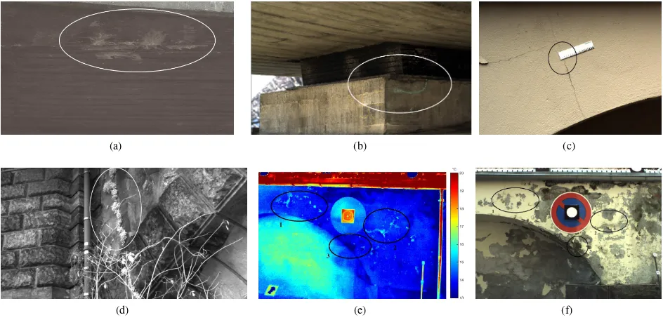
Figure 7: damage spots of: (a) efflorescence (RGB), (b) spalling on bridge bearing (RGB), (c) crack with a width of 0.2 mm (RGB), (d) vegetation on a sandstone bridge (NIR), (e) wet spot in circle 3 and replacement of coating from surface in circle 1 and 2 (TIR), (f) wet spot (circle 3) and replacement (circle 1 and 2) identified is not clearly visible in RGB image data.
the strips can be assigned to the low accuracy of the used IMU, which is designed for UAV navigation only.
In a second campaign, the LSRF was used on the ADFEX UAV for capturing a bridge with a length of 135 m (Mader et al., 2015). Scans alongside the bridge with low flight speed led to 20 000 scan lines in a flight-time of about 10 min. The resulting point cloud represents the bridge sufficiently and shows a root mean square errors (RMSE) of point deviations after ICP of about 31.7 cm compared to a terrestrial laser scanner point cloud as reference. Problems with the IMU were responsible for larger discrepan-cies.
Regarding the problems, which were encountered in the bridge and the lighthouse campaign, the data in both cases is sufficient for obstacle maps and an interactive mission planning by the user on-site. The utilization of real time kinematic (RTK) and differ-ential GNSS (DGNSS) method as well as a higher-quality IMU would improve the results significantly. Regarding this, (Eling et al., 2015) presented an UAV with high-performance positioning and navigation sensors as well as its potential of accuracy.
5.2 Visual inspections based on multispectal image data
The visual damage detection is an important aspect of building inspections. The quality, degree of detail and the completeness of the captured datasets are the basis for an appropriate assess-ment of the test engineer in regard to the further rehabilitation measures. For optimizing the resulting data the most influential parameters or factors are listed in the following:
• illumination of the region of interest
• exposure time
• gain value
• resolution
• focal length
• aperture
• calibrated lever arm and boresight angles.
For a good visibility of important building features a sufficient illumination of the damage spot is important. Deficits regarding this can be compensated with an integrated spotlight or by adapt-ing the exposure time, the gain value and the aperture. The expo-sure time is restricted by blur effects caused in UAV vibration and motion. A too high gain value leads to a quality reducing noise and an open aperture reduces the depth of field. It is important to find a good balance between this parameters. The degree of detail is mainly influenced by the sensor resolution and the focal length. The resolution is given in the most cases by sensor spec-ification, so the lens have to be adapted to the application. For a complete dataset a correct aligned UAV-sensor-system (lever arm and boresight angles) is necessary to guarantee the correct sensor orientation to the object.
To evaluate the potential of the sensor, some interesting damage spots were captured (Figure 7). In general, the majority of dam-age types or study features can be detected by using RGB imdam-age data. Figure 7a shows an efflorescence on the bottom side of the bridge, which indicates water emergence or moisture penetration. Spallings and cracks in the coating or in the concrete itself can be an indication for a settlement of the building. In this case, a multi-temporal measurement of the crack width is necessary to prevent static problems. Figure 7c shows, according to keep the safety distance, that crack widths of 0.2 mm are clearly identifiable. In Figure 7b a spalling on a bridge bearing (hard-to-access area) is recognizable. It can be assumed that other obvious damages such as contamination, concrete holes, rust marks, exposed rebars or foreign matters are also detectable in high-resolution RGB im-ages.
(a) (b)
(c) (d)
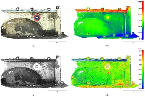
Figure 8: Multiattributed point cloud with: (a) RGB, (b) thermal, (c) near infrared and (d) band ratio parameter (BP RN I R−red)
attributes.
based on the camera channels, vegetation or other properties will become more visible.
Some building defects become visible by temperature differences on the building surface. Water-bearing cracks or wet spots, caused by a malfunctioning drainage system, have an other temperature than the surrounding dry surface and can be detected in thermal infrared image data. In the case of Figure 7e, the wall was heated by the sun, so that the wet spots had a lower temperature as the surface and appears as darker spots. An other damage is the re-placement of the coating from the building surface in an early stadium. This effect is not recognizable in RGB images (Figure 7f), but causes in temperature differences, which are visible as bright spots in thermal data (Figure 7e).
5.3 Imaged based 3D point clouds
This part of the contribution deals with 3D point clouds purely derived from image data. Three studies (RGB, thermal, multi-spectral imagery based point cloud) will be shown with regard to their accuracy and properties such as density and attributes. The reconstruction of all point clouds was carried out by using SfM tools. The principle of SfM-techniques in general can be found in further literature, e.g. (Koenderink and Van Doorn, 1991), (Beardsley et al., 1997) and (Pollefeys et al., 2000).
In a first investigation, a bridge was imaged by using the RGB camera mounted rigidly on an UAV (Mader et al., 2015). For this purpose, about 500 images were captured with an overlap of at least 80 %. On basis of this data the bridge was reconstructed by using SfM-tools, in detail with the commercial software package
Agisoft PhotoScan. As result, a dense point cloud with about 13 million points of the entire bridge was generated. Problems were gaps and inaccurate points on poorly-lit areas under the bridge.
A comparison with a terrestrial laser scanner point cloud showed RMS values of point deviations of 4.9 cm, whereby the majority of the points had deviations under 4.1 cm.
Westfeld et al. (2015) showed the generation of dense 3D point cloud purely based on thermal imagery. The complex fac¸ades of a courtyard building with dimensions of 50 m×50 m×20 m were captured in a raster pattern. On basis of about 15 000 images the reconstruction by SfM-tools (VisualSfM, Agisoft PhotoScan) and the dense point cloud generation were realized. Extensive accu-racy analyses showed that the achieved results with purely ther-mal images processed were good. The coordinates of reference target points were calculated by a spatial intersection method on basis of measured image coordinates and with SfM-tools deter-mined camera orientations. In lateral direction the RMSE was between 4 mm and 5 mm and in depth direction the RMSE was 18 mm.
∆φ[ ] 1.21 0.023 -0.85 0.028
∆κ[◦] -0.16 0.017 0.50 0.017
Table 3: Results of camera referencing consisting of lever arm(∆X,∆Y,∆Z) and boresight angles (∆ω,∆φ,∆κ) related to the camera own coordinate system of the RGB camera (z-axis points in direction of view, x-axis points right and y-axis points down).
camera XRM SE YRM SE ZRM SE
[mm] [mm] [mm]
near infrared 14.88 6.38 6.44
thermal 5.46 5.60 2.91
Table 4: RMSE of marker coordinates based on image point mea-surement, external and interior orientation of near infrared as well as thermal camera.
attributes are mapped to each point of the 3D point cloud. In addition, it is possible to calculate band ratio parameter for the entire point cloud on basis of the spectral attributes.
This workflow was tested in a practical study exemplary on a damaged wall with dimensions of 4.37 m in width, 2.0 m in height and 0.5 m in depth. Firstly, the calibration of the camera param-eter and the alignment of the cameras to each other were per-formed. The results of the lever arm and boresight angles are given in Table 3. The reconstruction was carried out on basis of 19 camera positions (approximatly rastered in a3×6 pat-tern) with an overlap of 70 % to 80 % in horizontal and about 70 % in vertical direction. For this study, the camera bar was mounted on a tripod. To simulate the situation on an UAV as realistic as possible, an exposure time of 1/500 s, an aperture of 5.6 , the auto-gain-mode and distances to the object with 4 m to 5 m were realized. The processed point cloud consists of about 2.9 million points (only wall) resulting in a point density of about 321 000 points/m2. Furthermore, the orientation parameter of the near infrared and the thermal camera were calculated and their attributes were mapped to each point of the point cloud (Figure 8a - 8b). To demonstrate the potential of combination the multi-spectral bands, a BRP for detection of living vegetation (Figure 8d) was calculated by using the gray values of the red and near infrared channel with:
BRPN I R−red=
N IR−red
N IR+red (1)
where
N IR : grey value of near infrared camera red : red channel of RGB camera
This BRP and other combination can be added to each 3D point with multispectral information.
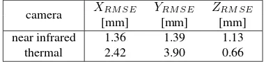
For an accuracy test, coded targets were attached to the wall and the 3D coordinates were estimated on basis of a convergent multi-image set, which was taken with a DSLR camera. The multi-image data was processed with the commercial software packageAICON 3D Studio. The coordinate system is oriented as follows: the surface of the wall forms the X-Z-plane and the Y-axis points into the wall. For the reference coordinates an accuracy of 0.10 mm in lateral direction and 0.12 mm in depth direction were achieved. To analyse the individual point precision, the coordinates of the
formation with fixed scale on basis of near infrared and thermal image data.
camera XRM SE YRM SE ZRM SE
[mm] [mm] [mm]
near infrared 1.06 1.13 2.55
thermal 1.48 1.46 1.03
Table 6: RMSE of marker coordinates of the calibration field.
target points were calculated on basis of measured image coordi-nates, determined camera pose and calibrated camera parameter from near infrared and thermal camera by using spatial intersec-tion. The RMSE of the coordinates are shown in Table 4. The result of the thermal camera is in an acceptable range with regard to the intended application and a ground sample distance (GSD) of 5.88 mm related to an object distance of about 4.5 m. The situ-ation is different to the RMSE of the object coordinates resulting from near infrared image data. An additional analysis of the re-sults, in detail a 3D Helmert transformation of the determined tar-get field coordinates (with fixed scale) to reference coordinates, shows a systematic error in this data. In Table 5 the RMSE af-ter the transformation are presented. Therefore, it is considered that the position of the near infrared camera has changed related to the other cameras in the time between the calibration and the measurement (few days). Consequently, the calibrated lever arm and boresight angles of the near infrared camera were not correct at the time of measurement. This fact is confirmed by carrying out the same procedure (used to the image data of the wall) with the multispectral image data of the calibration procedure. The re-sult is given in Table 6 and shows that the procedure works and the reachable accuracy of this system.
6. CONCLUSION AND PLACEMENT IN BUILDING INSPECTION
The paper presents a time- and cost-efficient UAV based system for building inspection tasks. On three flying robots special sen-sors, in detail a laser scanning range finder, a high resolution RGB camera and a multispectral camera system, were distributed for flexible mission execution. For evaluating the performance of each UAV-sensor combination, several practical studies were car-ried out. The results of the LSRF are sufficient for use as basis for on-site mission planning, obstacle maps and deriving geometrical properties of the investigation object. Further the object- as well as geo-referenced images of the high resolution RGB camera, the near infrared camera and the thermal camera fulfil the require-ments for detection and localization of the majority of damages on objects surface (visual inspection). Moreover the generation of geometrical high accurate and dense point clouds with differ-ent attributes was shown. The data is the basis for orthophotos or indices, which can be considered for an examination of the build-ing condition. Besides the advantages of the UAV based monitor-ing as well as the versatile and flexible applications, the follow-ing technical, environmental and legal aspects for UAV systems should be respected:
• need of flight permission
An other fact is, that is not possible to solve all required inspec-tion tasks. Image data is able to map all study features on the surface of the construction multispectral and in high resolution. But for example defects of the reinforcing steel will only be visi-ble due to surface spallings or rust marks on the concrete. Nevertheless, UAV-based damage detection is a helpful and flex-ible assisting tool in building inspection. The multispectral anal-ysis of building structures significantly facilitate the visual inter-pretation of feature conditions and damages.
7. FUTURE WORK
The results of the practical studies realized with the UAV system, indicate the potential of UAV-based building inspection. How-ever, technical limitations were pointed out. The accuracy of the rough point cloud based on LSRF data depends directly on the ac-curacy of determined UAV pose. Integrating RTK or DGNSS as well as higher-quality IMU for navigation solution on the UAVs would increase the quality of laser scanner point cloud signifi-cantly. A second aspect is to evaluate the improvement of image quality by using a spotlight. That is a important fact to guaran-tees a complete inspection also of poorly lit building areas. Fur-ther analysis of single point precision regarding the multispectral point cloud needs to be continued in future. Finally, the usability of appropriate indicies and orthophoto mosaic for building in-spection must be investigated.
ACKNOWLEDGEMENTS
The research work presented in this paper has been funded by the European Social Fund (ESF) via S¨achsische Aufbaubank (SAB). We would also like to thank our partners in the ADFEX project for their support and the great collaboration.
REFERENCES
BASt, 2007. Bundesanstalt f¨ur Straßenwesen: Richtlinien f¨ur die Erhaltung von Ingenieurbauten (RI-ERH-ING). Verkehrsbl.-Verlag Borgmann.
Beardsley, P. A., Zisserman, A. and Murray, D. W., 1997. Se-quential updating of projective and affine structure from motion. International Journal of Computer Vision 23(3), pp. 235–259.
DIN1076, 1999. DIN 1076, Normenausschuss Bauwesen: Inge-nieurbauwerke im Zuge von Straßen und Wegen, ¨uberwachung und Pr¨ufung, Ausgabe 11/1999.
DIN31051, 2003. DIN 31051: Grundlagen der Instandhaltung. Deutsches Institut f¨ur Normung, Berlin.
Eling, C., Wieland, M., Hess, C., Klingbeil, L. and Kuhlmann, H., 2015. Development and Evaluation of a UAV Based Mapping System for Remote Sensing and Surveying Applications. The International Archives of Photogrammetry, Remote Sensing and Spatial Information Sciences 40(1), pp. 233.
Eschmann, C., Kuo, C. M., Kuo, C. H. and Boller, C., 2012. Unmanned aircraft systems for remote building inspection and monitoring. In: 6th European Workshop on Structural Health Monitoring.
Klix, M., Schnitzer, F., Pfanne, M. and Janschek, K., 2014. Guidance-Navigation-Control System zur 3D-Exploration von ausgedehnten Objekten mit Multi-Roboter-Systemen. In: Deutscher Luft- und Raumfahrtskongress (DLRK).
Koch, K.-R., 1999. Parameter Estimation and Hypothesis Testing in Linear Models. Springer Science & Business Media.
Koenderink, J. J. and Van Doorn, A. J., 1991. Affine structure from motion. Journal of the Optical Society of America A 8(2), pp. 377–385.
Kriegler, F. J., Malila, W. A., Nalepka, R. F. and Richardson, W., 1969. Preprocessing transformations and their effects on multi-spectral recognition. In: Remote Sensing of Environment, VI, Vol. 1, p. 97.
Lag¨uela, S., Diaz-Vilarino, L., Roca, D. and Armesto, J., 2014. Aerial oblique thermographic imagery for the generation of building 3D models to complement Geographic Information Sys-tems. In: The 12th International Conference on Quantitative In-frared Thermography, Vol. 25.
Mader, D., Blaskow, R., Westfeld, P. and Maas, H.-G., 2015. UAV-based acquisition of 3D point cloud-a comparison of a low-cost laser scanner and SfM-tools. The International Archives of Photogrammetry, Remote Sensing and Spatial Information Sci-ences 40(3), pp. 335.
Mader, D., Westfeld, P. and Maas, H.-G., 2014. An inte-grated flexible self-calibration approach for 2D laser scanning range finders applied to the Hokuyo UTM-30LX-EW. ISPRS-International Archives of the Photogrammetry, Remote Sensing and Spatial Information Sciences 1, pp. 385–393.
Morgenthal, G. and Hallermann, N., 2014. Quality assessment of Unmanned Aerial Vehicle (UAV) based visual inspection of structures. Advances in Structural Engineering 17(3), pp. 289– 302.
Pollefeys, M., Koch, R., Vergauwen, M., Deknuydt, A. A. and Van Gool, L. J., 2000. Three-dimensional scene reconstruction from images. In: Electronic Imaging, International Society for Optics and Photonics, pp. 215–226.
Radke, S., 2014. Verkehr in Zahlen 2014/2015. Vol. 43, DVV Media Group, Hamburg.
Roca, D., Armesto, J., Lag¨uela, S. and D´ıaz-Vilari˜no, L., 2014. Lidar-equipped UAV for building information modelling. The International Archives of Photogrammetry, Remote Sensing and Spatial Information Sciences 40(5), pp. 523.
Rouse Jr, J. W., Haas, R. H., Schell, J. A. and Deering, D. W., 1974. Monitoring vegetation systems in the Great Plains with ERTS. Third ERTS-1 Symposium, NASA special publication 351, pp. 309–317.
Schach, R. and Weller, C., 2015. Bauwerks¨uberwachung mit Flu-grobotern. In: 19. Dresdner Baustatik-Semniar, Herausforderun-gen und neue L¨osunHerausforderun-gen fr die Tragwerksplanung, pp. 91–114.