Study on high resolution membrane-based diffractive optical imaging on geostationary orbit
Jiao Jianchaoa, *, Wang Baohua a, Wang Chao a, Zhang Yue a, Jin Jiangao a, Liu Zhengkun b, Su Yun a, Ruan Ningjuan a a
Beijing Institute of Space Mechanics & Electricity, Beijing 100094, China – ([email protected], [email protected], [email protected], [email protected], [email protected], [email protected], [email protected]) b
National Synchrotron Radiation Laboratory, University of Science and Technology of China, Hefei 230029, China - [email protected]
KEY WORDS: Diffractive Optics, Deployable, Achromatic, Geostationary Orbit, High Resolution, Membrane
ABSTRACT:
Diffractive optical imaging technology provides a new way to realize high resolution earth observation on geostationary orbit. There are a lot of benefits to use the membrane-based diffractive optical element in ultra-large aperture optical imaging system, including loose tolerance, light weight, easy folding and unfolding, which make it easy to realize high resolution earth observation on geostationary orbit. The implementation of this technology also faces some challenges, including the configuration of the diffractive primary lens, the development of high diffraction efficiency membrane-based diffractive optical elements, and the correction of the chromatic aberration of the diffractive optical elements. Aiming at the configuration of the diffractive primary lens, the “6+1” petal -type unfold scheme is proposed, which consider the compression ratio, the blocking rate and the development complexity. For high diffraction efficiency membrane-based diffractive optical element, a self-collimating method is proposed. The diffraction efficiency is more than 90% of the theoretical value. For the chromatic aberration correction problem, an optimization method based on schupmann is proposed to make the imaging spectral bandwidth in visible light band reach 100nm. The above conclusions have reference significance for the development of ultra-large aperture diffractive optical imaging system.
* Corresponding author
1. INTRODUCTION
Geostationary orbit high resolution optical imaging can obtain high temporal resolution and high spatial resolution images simultaneously, and can be fixed over the resident area for a long time, according to the need to quickly adjust the monitoring area, flexible task scheduling, continuously monitoring the environmental disaster and hot spots, within a narrow time window for time-sensitive targets monitoring, can meet the needs of a variety of fields, like environment, resources, meteorology, disaster reduction, emergency and military reconnaissance. It is an important developing direction of space optical remote sensing(Jianchao, 2016).
To realize high spatial resolution imagery from geostationary orbit, ultra-large aperture is needed. Especially for 1 meter spatial resolution imaging on geostationary orbit, over 20 meters aperture is needed. The benefits of having large aperture space optics are well known and there are extensive efforts aimed at learning how to field such systems. The reason they don't yet exist is simply that fielding large optics in space is exceedingly difficult. The two fundamental difficulties preventing the fielding of large aperture space optics are meeting the tight optical tolerances necessary to achieve high resolution images (furthermore, doing so across large apertures), and simultaneously dealing with the weight, packaging and deployability limitations of space implementation. Either of these challenges is, by itself, quite severe; In concert, they have proven to be unsolvable (Hyde, 2003).
To solve this problems, some new technologies were proposed, including space partitioning deployable technology, optical interferometric synthetic aperture imaging technique, sparse
aperture imaging technology(Nicholas, 2007) and diffractive optical imaging technology(Hyde, 2002).
Space partitioning deployable technology is a high cost way to realize ultra-large aperture, because there are a lot of hard work need to be overcome, like weigh-lightening of primary lens, rigid control of surface shape, accurate deployable structure, and wavefront sensing and control. Optical interferometric synthetic aperture imaging technique generally use several satellites flying in formation in order to achieve long baseline interferometry to achieve the high resolution imaging, but its satellite formation flight control accuracy is extremely high and difficult to implement the project. At the same time, the use of separate sparse aperture optical system, to achieve high resolution imaging at the expense of the luminous flux, and there is also a series of problems to be solved technically. On the other hand, the weight of separate sparse aperture optical system will still limit the expansion of aperture. Diffractive optical imaging technology provides a new way to realize high resolution earth observation on geostationary orbit(Jianchao, 2016).
There are a lot of benefits to use the membrane-based diffractive optical element in ultra-large aperture optical imaging system, including loose tolerance, light weight, easy folding and unfolding, which make it easy to realize high resolution earth observation on geostationary orbit. The implementation of this technology also faces some challenges, like diffractive optical imaging system design, large diffractive primary lens manufacture, large rigid-flexible coupling supporting structure, high accuracy control, etc.
2. DIFFRACTIVE OPTICAL IMAGING SYSTEM
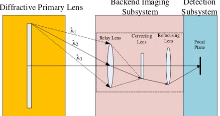
Diffractive optical remote sensor is based on the principle of the diffractive optical imaging technique to use planar diffractive optical element instead of the traditional transmissive or reflective optical element, as the large diameter primary lens of optical imaging system.
The configuration of diffractive optical remote sensor system as shown below, the system is mainly include diffractive optical
(2)Backend imaging subsystem: mainly responsible for a wide spectrum color correction and re-imaging. Wherein the relay lens is a conventional lens or reflector group, the role of the relay lens is to image the primary lens to correcting lens; Corrective lens is a small-diameter diffractive lens, mainly used to eliminate the dispersion effect of primary lens, and realize a wide spectral range; The refocusing lens is made of a conventional lens or reflector group, aiming at refocusing the light from corrective lens.
(3)Detection subsystem: realize photoelectric conversion and data processing.
Figure 1. Concept of diffractive optical imaging remote sensor
There are three key technologies in diffractive optical imaging system (about optics), including the configuration of the diffractive primary lens, the development of high diffraction efficiency membrane-based diffractive optical elements, and the correction of the chromatic aberration of diffractive optical system.
3. KEY TECHNOLOGIES IN DIFFRACTIVE OPTICAL IMAGING SYSTEM
3.1 Configuration of diffractive primary lens
There are some requirements for diffractive primary lens to realize a super-large diffractive optical imaging system with high performance and low complexity.
Diffractive primary lens is usually larger than 10 meters, so the diffractive primary lens must be folded up to satisfy the envelope constraint of rocket before launch. In addition, the folding and unfolding pattern of the primary lens must be satisfied with the optical imaging constraints.
Aiming at the configuration of the diffractive primary lens, the “6+1” petal-type unfold scheme is proposed, which compression ratio, blocking rate and development complexity were considered. This configuration contains 7 sub-lenses, 3 sub-lenses folded upwards, 3 sub-lenses folded downwards, the compression ratio is 2.1, blocking rate is 42.1%, and the fold and unfold complexity is lower than umbrella-type configuration.
Figure 2. Scheme of “6+1” petal-type configuration
3.2 High diffraction efficiency membrane-based diffractive optical element
For high diffraction efficiency membrane-based diffractive optical element, a self-collimating method is proposed. The diffraction efficiency is more than 90% of the theoretical value(Jian, 2016a).
Considering the frangibility and flexibility of thin membranes, multi-level surface features were initially made on fused silica substrate. Then, the liquid polymer was cast onto the substrate and cured in place. Finally, a free-standing patterned membrane was obtained after separation from the substrate. A schematic view of the self-aligned method is shown in Figure 3.The 4-level Fresnel zone lens (FZLs) can be fabricated in four steps using the proposed self-aligned method.
First, 4-level FZLs on fused silica were fabricated by twice UV lithography processes, the two masks with the modified alignment marks were made by a laser writer without overlay writing capability. Second, the 4-level profile fused silica substrate was cleaned and placed on the rotating platform, liquid polyimide was cast onto the substrate. Third, the liquid polyimide was allowed to flow for a while to the edge of the substrate, and spin-coating was done afterwards. Then a second layer of liquid polyimide was cast onto the first layer, and the spin-coating was done in the same way. After that, the liquid polyimide and the substrate were placed in a temperature control box for roasting after a 24-hour stay in room temperature to minimize the membrane surface fluctuation. Finally, we obtained the patterned replica polyimide membrane after separation from the substrate(Jian, 2016b).
Figure 3. Fabrication process of 4-level membrane FZLs using self-aligned method
By using the self-aligned method, a 4-level membrane FZL in 200 mm diameter was made. Figure 4 shows a 4-level membrane FZLs in 200 mm diameter successfully released from substrate.
Figure 4. A 4-level membrane FZLs in 200 mm diameter
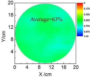
The full-aperture diffraction efficiency is 63%, which is only 1.8% below the theoretical value of 64.8%, as shown in Figure 5. The measured etched depth of each step deviates about 5% from design value. The data imply that the fabrication errors are well controlled.
Figure 5. Diffraction efficiency of a 4-level membrane FZLs
The full aperture membrane thickness uniformity is measured by use of interferometer. During the measurement, the membrane is laid between the interferometer and a mirror, when the collimated light pass through the membrane twice and interfere with each other, the interference fringes shows the membrane thickness uniformity. As shown in Figure 6, the thickness variation of the 200 mm aperture membrane is 30 nm (RMS).
Figure 6. Thickness uniformity of a membrane in 200 mm diameter
3.3 Chromatic aberration correction
For the chromatic aberration correction problem, an optimization method based on schupmann is proposed to make the imaging spectral bandwidth in visible light band reach 100nm(Jianchao, 2016).
For broad spectrum color correction problem, usually the traditional Schupmann methods can be better corrected wide spectral range of color, and you can get a better imaging effect, can theoretically achieve full visible spectrum chromatic correction. But there is a serious problem with this approach, which is a compressed version of the correction mirror primary lens of the diffractive optical ring with the same number, which leads to the main processing diffractive optical lens, a relay lens group, corrective lenses such as alignment tolerances are very strict, only when the diffractive optical primary lens F number is large, the tolerance will be relatively relaxed, easier to achieve, such as pre-project Eyeglass using this program were achieved 200mm, 500mm aperture ground prototype diffractive optical primary lens F number average is 100, the imaging Bandwidth 230nm, but this program will cause the system to long length, the length of two ground Eyeglass project prototypes are greater than 20m, 50m, difficult to achieve large space applications. Only when the diffractive optical primary lens F number is small, the system length is short enough to be able to meet the needs of space applications, but will result in the optical tolerances of the optical system are very strict at this time, especially for large-aperture optical system, it is difficult to achieve.
To solve the problem of bandwidth constraints, tolerances, system length of the system, based on traditional Schupmann method, we propose a "balanced match achromatic" concept to correct the dispersion. This method does not require the number of annulus of corrective lens as the same to primary lens, but use the back-end imaging subsystem to balance the whole The International Archives of the Photogrammetry, Remote Sensing and Spatial Information Sciences, Volume XLII-1/W1, 2017
dispersion produced by the primary lens. By adopting this method, we designed a 200mm diameter diffractive optical system, a diffractive optical primary lens F number of 10, the imaging bandwidth of 100nm, the length of the system 2. 39mm, 8.3 times shorter than the Eyeglass program, while processing all lens groups, alignment tolerances are in the current process alignment within the ability range.
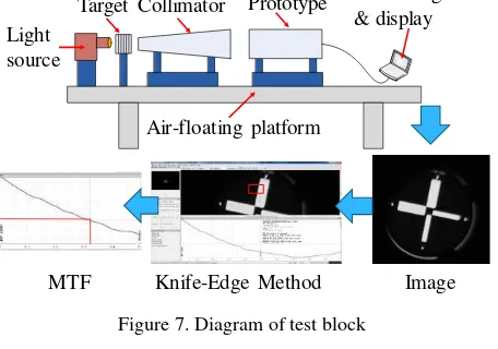
According to the chromatic aberration correction method we proposed, a prototype was developed and tested. Figure 7 shows the prototype on testbed. Figure 8 shows the prototype on testbed. Figure 9 shows the test results. The test results show that the prototype MTF is 0.3 (@Nyquist frequency), meet the actual optical system design requirements and achieve 100nm bandwidth correction.
Figure 7. Diagram of test block
Processing optical imaging system, including configuration of diffractive
optical imaging system, high diffraction efficiency membrane-based diffractive optical element, and chromatic aberration correction.
For the configuration of the diffractive primary lens, the “6+1” petal-type unfold scheme was proposed, realize 2.1 compression ratio and 42.1% blocking rate. For high diffraction efficiency membrane-based diffractive optical element, a self-collimating method is proposed, and a 4-level membrane was produced to demonstrate the method, 63% diffraction efficiency and 30 nm thickness uniformity was realized. For the chromatic aberration correction problem, an optimization method based on schupmann was proposed and demonstrated, we developed a prototype with 100 nm bandwidth in visible light for the demonstration.
The above conclusions have reference significance for the development of ultra-large aperture diffractive optical imaging system.
REFERENCES
David, W., 2015. MOIRE Primary Diffractive Optical Element Structure Deployment Testing. 2nd AIAA Spacecraft Structures Conference, 2015, Kissimmee, Florida.
Hyde, R., 1996. Eyeglass, a large aperture space telescope. UCRL-ID-125366, Lawrence Livermore National Laboratory, Livermore, USA.
Hyde, R., 2002. Eyeglass: A Very Large Aperture Diffractive Space Telescope, 4849(4).
Hyde, R., 2003. Eyeglass Large Aperture, Lightweight Space Optics FY2000-FY2002 LDRD Strategic Initiative, Report UCRL-ID-151390, Lawrence Livermore National Laboratory, USA.
Jeanette, L., 2014. MOIRE: Ground Test Bed Results for a Large Membrane Telescope, AIAA 2014-1510
Jian Z., 2016a. Fabrication of large-aperture and high efficiency Fresnel diffractive membrane optic using a self-aligned method, Optik, 127(2016), pp. 9833–9839
Jian Z., 2016b. Low-cost method of fabricating large-aperture, high efficiency, Fresnel diffractive membrane optic using a modified moiré technique, CHINESE OPTICS LETTERS, 14(10), pp. 100501-1–100501-5
Jianchao, J., 2016. Imaging performance tests of diffractive optical system, Proc. of SPIE Vol. 10022, pp. 1002216-1-1002216-9
Nicholas, J., 2007. Optical sparse aperture imaging. Applied Optics, 46(23), pp. 5933-5943
Paul, A., 2012. MOIRE - Initial Demonstration of a Transmissive Diffractive Membrane Optic for Large Lightweight Optical Telescopes,” Proceedings of SPIE - The International Society for Optical Engineering, v 8442, 2012, Space Telescopes and Instrumentation 2012: Optical, Infrared, and Millimeter Wave
Paul, A., 2014. MOIRE – Ground Demonstration of a Large Aperture Diffractive Transmissive Telescope, Space Telescopes The International Archives of the Photogrammetry, Remote Sensing and Spatial Information Sciences, Volume XLII-1/W1, 2017
and Instrumentation 2014: Optical, Infrared, and Millimeter Wave, Proc. of SPIE Vol. 9143, pp. 91431W-1-14
Tao, Z., 2012. Application of Zone Plate Diffractive Imaging Technology in Earth Observation Satellites, Spacecraft Engineering, 21(3)
Tandy, W., 2013. MOIRE Gossamer Space Telescope – Challenges and Solutions in Large Scale Testing. 54th AIAA/ASME/ASCE/AHS/ASC Structures, Structural Dynamics, and Materials Conference, Paper 1514119.