PERFORMANCE EVALUATION OF UNCOATED AND COATED CARBIDE TOOLS WHEN END MILLING OF TITANIUM ALLOY USING
RESPONSE SURFACE METHODOLOGY
AMRIFAN SALADIN MOHRUNI
“We hereby declare that we have read this thesis and in our opinion this thesis is sufficient in terms of scope and quality for the award of the degree of Doctor of Philosophy (Mechanical Engineering)”
Signature : ………..……..…………...
Name of Supervisor I : Prof. Dr. Safian Sharif………..
Date : ………..……
Signature : ………..………...
Name of Supervisor II : Assoc. Prof. Dr. Noordin Mohd. Yusof
Date : ………..
Signature : ………..………….…………...
Name of Supervisor III : Prof. Dr. V.C. Venkatesh…….…….
Date : ………..……
BAHAGIAN A – Pengesahan Kerjasama*
Adalah disahkan bahwa projek penyelidikan tesis ini telah dilaksanakan melalui kerjasama antara _________________________ dengan ______________________
* Jika penyediaan tesis/projek melibatkan kerjasama.
BAHAGIAN B – Untuk Kegunaan Pejabat Sekolah Pengajian Siswazah
Tesis ini telah diperiksa dan diakui oleh:
Nama dan Alamat Pemeriksa Luar : Prof. Dr. Che Hassan bin Che Haron
Fakulti Kejuruteraan,
Jabatan Kejuruteraan Mekanik & Bahan,
Universiti Kebangsaan Malaysia,
43600 Bangi, Selangor
Nama dan Alamat Pemeriksa Dalam I : Assoc. Prof. Dr. Mohd Hasbullah bin Idris
Fakulti Kejuruteraan Mekanikal,
UTM, Skudai
Nama dan Alamat Pemeriksa Dalam : Assoc. Prof. Dr. Ali bin Ourdjini
Faculty of Mechanical Engineering
UTM, Skudai
Nama Penyelia Lain (jika ada) :
Disahkan oleh Timbalan Pendaftar di SPS:
PERFORMANCE EVALUATION OF UNCOATED AND COATED CARBIDE TOOLS WHEN END MILLING OF TITANIUM ALLOY USING
RESPONSE SURFACE METHODOLOGY
AMRIFAN SALADIN MOHRUNI
A thesis submitted in fulfilment of the requirements for the award of the degree of Doctor of Philosophy (Mechanical Engineering)
Faculty of Mechanical Engineering Universiti Teknologi Malaysia
ii
I declare that this thesis entitled “Performance Evaluation of Uncoated and Coated Carbide Tools when End Milling of Titanium Alloy using Response Surface
Methodology” is the result of my own research except as cited in the references. The thesis has not been accepted for any degree and is not concurrently submitted in candidature of any other degree.
Signature :
Name : AMRIFAN SALADIN MOHRUNI
iii
To my grandfathers, my parents, my brothers, my beloved wife and sons,
Alif Tias Mangkunegara, Anugerah Al-Amin Mangkunegara,
Noordin As-Shiddiq Mangkunegara and M. Rafif Al-Farouq Mangkunegara
iv
ACKNOWLEDGEMENTS
All praise to Allah, the Almighty, most Gracious and most Merciful, Who has created the mankind with knowledge, wisdom and power, for His guidance and help in giving me the strength and motivation to complete this thesis. A special thank you to all of my supervisors, Prof. Dr. Safian Sharif, Assoc. Prof. Dr. Noordin Mohd. Yusof and Prof. Dr. V.C. Venkatesh, for their continuous support, assistance and encouragement and for providing the opportunity to conduct this research during my pleasant stay at Production Laboratory, FKM, UTM.
I would like also to express my gratitude to all of the staff in the Production Laboratory at Faculty of Mechanical Engineering, Universiti Teknologi Malaysia, especially to Mr. Sazali Ngadiman, Mr. Maizan Sulaiman, Mr. Aidid Hussin and Mr. Mahudin Abdul Rahim for their effort in assisting me in the various workshop and laboratory tasks.
I am indebted to Universiti Teknologi Malaysia for providing me financial support during the period of this research work and to the Ministry of Science Technology and Environment for awarding my supervisor the IRPA grant (vote: 74122), which has enabled the purchase of some of necessary research equipment and materials.
v
ABSTRACT
vi
ABSTRAK
vii
TABLE OF CONTENTS
CHAPTER TITLE PAGE
DECLARATION ii
DEDICATION iii
ACKNOWLEDGEMENTS iv
ABSTRACT v
ABSTRAK vi
TABLE OF CONTENTS vii
LIST OF TABLES xvi
LIST OF FIGURES xvii
LIST OF ABBREVIATIONS xxvii
LIST OF SYMBOLS xxviii
LIST OF APPENDICES xxix
1 INTRODUCTION 1
1.1 Overview 1
1.2 Background of the Problem 1
1.3 Statement of the Problem 2
1.4 Objective of the Study 4
1.5 Significance of the Study 4
viii
2 LITERATURE REVIEW 6
2.1 Introduction to Metal Cutting 6
2.2 End Milling 6
2.2.1 Cutting Force 8
2.2.2 The Static Cutting Force 8
2.2.3 Cutting Force in End Milling 10 2.2.4 Relationship between Table and Cutter System
of Cutting Force 12
2.3 Cutting Tool 13
2.3.1 Cutting Tool Materials 15
2.3.1.1 Unalloyed and Low-Alloy Tool Steel 16 2.3.1.2 High Speed Steel (HSS) 16
2.3.1.8 Polycrystalline Diamond (PD) 22
2.3.2 Cutting Tool Coatings 22
2.3.2.1 Chemical Vapors Deposition (CVD) 23 2.3.2.2 Physical Vapors Deposition (PVD) 25 2.3.2.3 Composite CVD + PVD Coatings 27 2.3.2.4 TiAlN Based Coated Tools 28
2.4 Tool Wear in End Milling 29
2.4.1.6 Edge Chipping or Frittering 33
2.4.1.7 Tool Fracture 33
2.4.2 Tool Wear Mechanism 33
ix
2.4.2.2 Abrasive Wear 34
2.4.2.3 Diffusion or Solution Wear 35
2.4.2.4 Oxidation 35
2.4.2.5 Chemical Wear or Corrosion 36
2.5 Surface Roughness 36
3 DESIGN OF EXPERIMENT AND
RESPONSE SURFACE METHODOLOGY 39
3.1 Design of Experiment (DOE) 39
3.2 Response Surface Methodology 40
3.2.1 The Response Function and the Response Surface 41 3.2.2 Representation of the Response Surface by Contours 42
3.3 Central Composite Design (CCD) 44
3.3.1 General Steps Involved in Application of CCD 47 3.3.1.1 Postulation of Mathematical Models 47 3.3.1.2 Coding for the Independent Variables 50 3.3.1.3 Estimation of Model Parameters 51
3.3.1.4 Analysis of Results 52
4 EXPERIMENTAL SETUP AND METHOD OF
EXPERIMENTATION 53
4.1 Introduction 53
4.2 Cutting Tool 53
4.3 Workpiece Material 54
4.4 Experimental Design and Planning 55
4.5 Experimental Works 57
4.5.1 Cutting Force Measurement 57
4.5.2 Tool Wear Measurement and Tool Life 59 4.5.3 Surface Roughness Measurement 60
5 EXPERIMENTAL RESULTS FOR UNCOATED TOOLS 62 5.1 Development of Tool Life Models for Uncoated Carbide
Tools 62
x 5.1.2 Postulation of the Mathematical Models 63
5.1.3 Experimental Design 65
5.1.4 Coding of the Independent Variables 66 5.1.5 Analysis of the Tool Life Results 68
5.1.5.1 Development of the First Order Model
using 2k-Factorial Design 68 5.1.5.2 Development of the Second Order Model
using CCD 72
5.1.5.3 Development of the First Order Model
using CCD 75
5.2 Development of Surface Roughness Models
for Uncoated Carbide Tools 78
5.2.1 Introduction 78
5.2.2 Postulation of the Mathematical Models 79 5.2.3 Analysis of the Surface Roughness Results 81
5.2.3.1 Development of the mathematical model using 2k-factorial design 81 5.2.3.2 Development of the Second Order Model
using CCD 83
5.2.3.3 Development of the First Order Surface
Roughness Model using CCD 85 5.3 Development of Cutting Force Models for Uncoated
Carbide Tools 87
5.3.1 Introduction 87
5.3.2 Postulation of the Mathematical Models 88 5.3.3 Analysis of Cutting Force Results 89
5.3.3.1 Development of the Mathematical Model using 2k-Factorial Design 89 5.3.3.2 Development of the First Order Model
using CCD 93
5.3.3.3 Development of the Second Order Model
using CCD 97
5.4 Optimization of the Mathematical Models for Uncoated
xi
5.4.1 Introduction 102
5.4.2 Selection of Validated Model Combinations 103 5.4.3 First Combination of Validated Model 104 5.4.4 Second Combination of Validated Model 106
6 EXPERIMENTAL RESULTS OF TiAlN-COATED TOOLS 109 6.1 Development of Tool Life Models for TiAlN
Coated Carbide Tools 109
6.1.1 Tool Life Results 109
6.1.2 Analysis of the Tool Life Results for TiAlN
Coated End Mills 110
6.1.2.1 Development of the Tool Life Model
using 2k-Factorial Design 111 6.1.2.2 Development of the Tool Life Model
using 2nd Order CCD 114
6.1.2.3 Development of the Tool Life Model
using 1st Order CCD 117
6.2 Development of Surface Roughness Models for TiAlN
Coated Carbide Tools 121
6.2.1 Surface Roughness Results 121
6.2.2 Analysis of the Surface Roughness Results 122 6.2.2.1 Development of the Surface Roughness
Model using 2k-Factorial Design 122 6.2.2.2 Development of the Surface Roughness
Model using 2nd Order CCD 126 6.2.2.3 Development of the Surface Roughness
Model using 1st order CCD 130 6.3 Development of Cutting Force Models for TiAlN
Coated Carbide Tools 132
6.3.1 Cutting Force Results 132
6.3.2 Analysis of Cutting Force Results 133 6.3.2.1 Development of the Cutting Force
xii 6.3.2.2 Development of the First Order
Cutting Force Model using CCD 137 6.3.2.3 Development of the Second Order
Cutting Force Model using CCD 141 6.4 Optimization of the Mathematical Models for TiAlN
Coated Carbide Tools 146
6.4.1 Selection of Validated Model Combinations 146 6.4.2 First Combination of Validated Model 147 6.4.3 Second Combination of Validated Model 150
7 EXPERIMENTAL RESULTS FOR SUPER NITRIDE
COATED TOOLS 152
7.1 Development of Tool Life Models for SNTR coated
Carbide Tools 152
7.1.1 The Tool Life Experimental Results 152 7.1.2 Analysis of the Tool Life Results for SNTR
Coated End Mills 153
7.1.2.1 Development of the Tool Life Model
using 2k-Factorial Design 154 7.1.2.2 Development of the Tool Life Model
using 2nd Order CCD 157
7.1.2.3 Development of the Tool Life Model
using 1st Order CCD 161
7.2 Development of Surface Roughness Models for SNTR
Coated Carbide Tools 163
7.2.1 The Surface Roughness Experimental Results 163 7.2.2 Analysis of the Surface Roughness Results 164
7.2.2.1 Development of the Surface Roughness
Model using 2k-Factorial Design 164 7.2.2.2 Development of the Surface Roughness
Model using 2nd Order CCD 168 7.2.2.3 Development of the Surface Roughness
xiii 7.3 Development of Cutting Force Models for SNTR
Coated Carbide Tools 175
7.3.1 The Cutting Force Experimental Results 175 7.3.2 Analysis of Cutting Force Results 176
7.3.2.1 Development of the Cutting Force Model using 2k-Factorial Design 176 7.3.2.2 Development of the First Order Model
using CCD 180
7.3.2.3 Development of the Second Order Model
using CCD 184
7.4 Optimization of the Mathematical Models for SNTR
Coated Carbide Tools 190
7.4.1 Selection of Validated model combinations 190 7.4.2 First Combination of Validated Model 191 7.4.3 Second Combination of Validated Model 194
8 DISCUSSION 197
8.1 Comparison of Validated Tool Life Models 197 8.1.1 Comparing Response Surfaces of Validated
Tool Life Models 198
8.1.1.1 Comparison Response Surface of Validated Tool Life Models
for Cutting Speed and Feed 198 8.1.1.2 Comparison of Response Surface of
Validated Tool Life Models
for Cutting Speed and Radial Rake Angle 203 8.1.1.3 Comparison Response Surface of
Validated Tool Life Models
for Feed and Radial Rake Angle 205 8.1.2 Comparison of Optimum Cutting Condition
for Validated Tool Life Models 207 8.2 Comparison of Validated Surface Roughness Models 208
8.2.1 Comparing Response Surfaces of Validated Surface
xiv 8.2.1.1 Comparison Response Surface of
Validated Surface Roughness Models
for Cutting Speed and Feed 210 8.2.1.2 Comparison Response Surface of
Validated Surface Roughness Models
for Cutting Speed and Radial Rake Angle 212 8.2.1.3 Comparison Response Surface of Validated
surface Roughness Models for
Feed and Radial Rake Angle 214 8.2.2 Comparing Optimum Cutting Condition of
Validated Surface Roughness Models 216 8.3 Comparison of Validated Cutting Force Models 217
8.3.1 Comparing Response Surfaces of Validated
Cutting Force Models 218
8.3.1.1 Comparison Response Surface of Validated Cutting Force Models for
Cutting Speed and Feed 218
8.3.1.2 Comparison Response Surface of Validated Cutting Force Models for Cutting Speed
and Radial Rake Angle 221
8.3.1.3 Comparison Response Surface of Validated Cutting Force Models for Feed
and Radial Rake Angle 223
8.3.2 Comparing Optimum cutting Condition of validated
Cutting Force Models 225
9 CONCLUSIONS 226
9.1 Conclusions 226
9.1.1 The Best Performer for All Types of Cutting Tools 226 9.1.2 Optimum Cutting Conditions for All Types
of Cutting Tools 227
9.1.3 The Best Mathematical Models for All Types
of Cutting Tools 228
xv
REFERENCES 230
xvi
LIST OF TABLES
TABLE NO. TITLE PAGE
3.1 ANOVA for significance of regression in multiple regression 52 4.1 Properties of cutting tool used in the experiments 54 4.2 Mechanical properties of Ti-6Al-4V at room temperature 55
4.3 Chemical properties of Ti-6Al-4V 55
4.4 Coding of the cutting conditions for experimentations 57 5.1 Levels of the independent variables and coding for tool life models 67 5.2 Tool life results for uncoated carbide tools 67 5.3 Surface roughness results for uncoated carbide tools 80 5.4 Cutting force results for uncoated carbide tools 89 6.1 Tool life results for TiAlN-coated carbide tools 110 6.2 Surface roughness results for TiAlN coated carbide tools 121 6.3 Cutting force Fc when using TiAlN coated carbide tools 133 7.1 Tool life results for SNTR coated solid carbide tools 153 7.2 Surface roughness results for SNTR coated carbide tools 164 7.3 Cutting force results for SNTR coated carbide tools 176
8.1 Summary of validated tool life models 201
xvii
LIST OF FIGURES
FIGURE NO. TITLE PAGE
2.1 Type of milling operation (Stephenson and Agapiou, 1997) 7 2.2 Schematic view of the up- and down milling approaches
(Stephenson and Agapiou, 1997) 8
2.3 Cutting force components acting on one tooth of an end mill (Alauddin, 1993; Alauddin and El-Baradie, 1996;
Alauddin et.al., 1996ab) 10
2.4 End mill geometry (Stephenson and Agapiou, 1997) 14 2.5 Toughness and hardness for each cutting tools material
(Stephenson and Agapiou, 1997) 16
2.6 Differences in deposition techniques
(Toenshoff and Blawit, 1997) 25
2.7 Deposition techniques (Prengel et. al., 1998) 27 2.8 PVD deposition process for TiAlN coatings
(Prengel et. al., 1997) 29
2.9 Type of wear on end mill after ISO8688-2 30
2.10 Variation of the flank wear rate with cutting time,
showing the initial wear, steady wear, and severe wear periods
(Stephenson and Agapiou, 1997) 31
2.11 Wear mechanisms in cutting tools
(Koenig, 1990; Toenshoff, 1995) 34
2.12 Fishbone diagram with the parameter that affect
xviii 2.13 Classification of surface roughness formation related
to DIN 4760 (Colak et. al. 2007) 38
2.14 Surface roughness profile (Colak et. al. 2007) 38 3.1 A three dimensional response surface showing the expected
yield (η) as a function of temperature (x1) and pressure (x2)
(Myers and Montgomery, 2002) 43
3.2 A contour plot of response surface
(Myers and Montgomery, 2002) 43
3.3 The 23-factorial design augmented with 4 center points 45
3.4 The second order CCD for k = 3 46
4.1 The 23-factorial design augmented with 4 center points and
linear CCD design 56
4.2 The second order CCD for k = 3 56
4.3 CNC MAHO MH 700S machine centre 58
4.4 Experimental set-up 58
4.5 A multi component force measuring system 59
4.6 Nikon tool makers’ microscope for wear measurement 60 4.7 Zeiss Stemi 2000-C microscope for capturing micrograph
images 60 4.8 Taylor Hobson Surftronic+3 for measuring surface roughness 61
5.1 Contour of standard error design for 3F1-model 68
5.2 Main effect occurred in 3F1-model 69
5.3 ANOVA for 3F1-model with nc = 4 69
5.4 Box-Cox plot analysis for 3F1-model with nc = 4 70
5.5 Response surface for 3F1-tool life model with nc = 4 71
5.6 Standard deviation for the second order CCD model 72 5.7 Fit and summary test for the second order CCD model 73
5.8 ANOVA for the second order CCD model 73
5.9 Box-Cox Plot Analysis for the second order CCD model 74 5.10 Response surface of CCD quadratic-tool life model 75 5.11 Standard deviation for the first order CCD model 76 5.12 Fit and summary test for the first order CCD design 76
5.13 ANOVA for the first order CCD design 77
xix 5.15 Main effect occurred in 3F1- surface roughness model 81
5.16 ANOVA for 3F1-surface roughness model 82
5.17 Response surface for 3F1-surface roughness model 83 5.18 Fit and summary test for CCD-surface roughness model 84
5.19 ANOVA for CCD-surface roughness model 84
5.20 Response surface for surface roughness second order
CCD model 85
5.21 Fit and summary test for the first order surface roughness
CCD model 86
5.22 ANOVA for the first order surface roughness CCD model 87 5.23 Main Effect occurred in 3F1-cutting force model 90
5.24 ANOVA for 3F1-cutting force model 91
5.25 Response surface of AC for 3F1-cutting force model 92 5.26 Response surface of BC for 3F1-cutting force model 92 5.27 Fit and summary test for the first order cutting force
CCD model 93
5.28 ANOVA for the first order cutting force CCD model 94 5.29 Response surface of AB for the first order cutting force
CCD model 95
5.30 Response surface of AC for the first order cutting force
CCD model 95
5.31 Response surface of BC for the first order cutting force
CCD model 96
5.32 ANOVA for the second order cutting force CCD model 97 5.33 Response surface AB for the second order cutting force
CCD model 98
5.34 Response surface AC for the second order cutting force
CCD model 99
5.35 Response surface BC for the second order cutting force
CCD model 100
5.36 ANOVA elimination for the second order cutting force
CCD model 101
xx 5.39 First desirability of validated mathematical model 105 5.40 Overlay plot of desirable first optimized mathematical model 105 5.41 Second numerical optimization of validated mathematical
model 106 5.42 Second desirability of validated mathematical model 107
5.43 Overlay plot of desirable second optimized mathematical
model 108 6.1 Main effect occurred in 3F1-model for TiAlN coated end mil 111
6.2 ANOVA for 3F1-model of TiAlN coated end mills with nc = 4 112
6.3 Response Surface of 3F1-model with nc = 4 for V and fz
using TiAlN coated end mills 113
6.4 Response Surface of 3F1-model with nc = 4 for fz and γ
using TiAlN coated end mills 113
6.5 Fit summary test for the 2nd order CCD using TiAlN
coated end mills 114
6.6 ANOVA for the second order CCD tool life model
using TiAlN coated tools 115
6.7 Response surface of CCD quadratic-tool life model
for V and fz using TiAlN coated end mills 116
6.8 Response surface of CCD quadratic-tool life model
for fz and γ using TiAlN coated end mills 117
6.9 Fit and summary test for the first order CCD tool life model
using TiAlN coated end mills 118
6.10 ANOVA for the first order CCD tool life model
using TiAlN coated tools 119
6.11 Response surface of the first order CCD tool life model
for V an fz using TiAlN coated tools 119
6.12 Response surface of the first order CCD tool life model
for fz and γ using TiAlN coated tools 120
6.13 Main effect occurred in 3F1- surface roughness model
for TiAlN coated tools 122
6.14 ANOVA for 3F1-surface roughness model
xxi 6.15 Response surface of 3F1-surface roughness model
for V and fz using TiAlN coated tools 124
6.16 Response surface for 3F1-surface roughness model
for fz and using TiAlN coated tools 125
6.17 Response surface for 3F1-surface roughness model
for V and usingTiAlN coated tools 125 6.18 Fit and Summary Test for CCD-surface roughness model
for TiAlN coated tools 126
6.19 ANOVA for the 2nd order CCD-surface roughness model
for TiAlN coated tools 127
6.20 Response surface of the 2nd order CCD -surface roughness
model for V and fz using TiAlN coated tools 128
6.21 Response surface of the 2nd order CCD -surface roughness
model for V and usingTiAlN coated tools 128 6.22 Response surface of the 2nd order CCD -surface roughness
model for fz and usingTiAlN coated tools 129
6.23 ANOVA for the simplified 2nd order CCD-surface
roughness model for TiAlN coated tools 130 6.24 Fit and Summary Test for the first order surface roughness
CCD model for TiAlN coated tools 131
6.25 ANOVA for the first order surface roughness CCD model
for TiAlN coated tools. 132
6.26 Main effect occurred in 3F1-cutting force model
for TiAlN coated tools 134
6.27 ANOVA for 3F1-cutting force model for TiAlN coated tools 135 6.28 Response surface of the 3F1-cutting force model for
for V and fz using TiAlN coated tools 135
6.29 Response surface of the 3F1-cutting force model for
fz and using TiAlN coated tools 136
6.30 Response surface of the 3F1-cutting force model for
V and using TiAlN coated tools 136
6.31 Fit and Summary Test for the first order cutting force
xxii 6.32 ANOVA for the first order cutting force CCD model
for TiAlN coated tools 139
6.33 Response surface of the first order cutting force CCD model
for V and fz using TiAlN coated tools 139
6.34 Response surface of the first order cutting force CCD model
for V and usingTiAlN coated tools 140 6.35 Response surface of the first order cutting force CCD model
for fz and usingTiAlN coated tools 140
6.36 ANOVA of the second order cutting force CCD model
for TiAlN coated tools 142
6.37 Response surface of the second order cutting force CCD
model for V and fz using TiAlN coated tools 143
6.38 Response surface of the second order cutting force CCD
model for V and using TiAlN coated tools 143 6.39 Response Surface of the second order cutting force CCD
model for fz and using TiAlN coated tools 144
6.40 ANOVA elimination of the second order cutting force
CCD model for TiAlN coated tools 145
6.41 Optimization combination of validated mathematical model
for TiAlN coated tools 147
6.42 First numerical optimization of validated mathematical model 148 6.43 First desirability of validated mathematical model 148 6.44 Overlay plot of desirable first optimized mathematical model 149 6.45 Second numerical optimization of validated mathematical
model 150 6.46 Second desirability of validated mathematical model 151
6.47 Overlay plot of desirable second optimized mathematical
model 151 7.1 Main effect occurred in 3F1-model for SNTR coated end mil. 154
7.2 ANOVA for 3F1-model of SNTR coated end mills with nc = 4. 155
7.3 Response surface for 3F1-model with nc = 4 for
V and fz using SNTR coated tools 156
7.4 Response surface for 3F1-model with nc = 4 for
xxiii 7.5 Response surface for 3F1-model with nc = 4 for
fz and using SNTR coated tools 157 7.6 Fit and summary test for the 2nd order tool life CCD model
using SNTR coated tools. 158
7.7 ANOVA for the 2nd order CCD tool life model
using SNTR coated tools. 158
7.8 Response surface of CCD quadratic-tool life model
for V and fz using SNTR coated solid carbide tools. 159
7.9 Response surface of CCD quadratic-tool life model
for V and γ using SNTR coated solid carbide tools. 160 7.10 Response surface of CCD quadratic-tool life model
for fz and γ using SNTR coated solid carbide tools. 160
7.11 Fit and summary test for the first order CCD design
using SNTR coated solid carbide tools. 162 7.12 ANOVA for the first order CCD tool life model
using SNTR coated solid carbide tools. 163 7.13 Main effect occurred in 3F1- surface roughness model
using SNTR- coated solid carbide tools. 165 7.14 ANOVA for 3F1-surface roughness model using SNTR
coated solid carbide tools.. 166
7.15 Response surface of 3F1-surface roughness model
for V and fz using SNTR coated solid carbide tools. 167 7.16 Response surface of 3F1-surface roughness model
for V and γo using SNTR coated solid carbide tools. 167
7.17 Response surface for 3F1-surface roughness model
for fz and γo using SNTR coated solid carbide tools. 168
7.18 Fit and summary test for CCD-surface roughness model
for SNTR coated tools. 169
7.19 ANOVA for the 2nd order CCD-surface roughness model
for SNTR coated tools. 170
7.20 Response surface of the 2nd order CCD -surface roughness
model for V and fz using SNTR coated solid carbide tools. 170
7.21 Response surface of the 2nd order CCD -surface roughness
xxiv 7.22 Response surface of the 2nd order CCD -surface roughness
model for fz and using SNTR coated solid carbide tools. 171 7.23 Fit and summary test for the first order surface roughness
CCD model using SNTR coated solid carbide tools. 172 7.24 ANOVA for the first order surface roughness CCD
model using S-Nitride coated solid carbide tools. 173 7.25 Response surface of the 1st order CCD -surface roughness
model for V and fz using SNTR coated solid carbide tools. 174
7.26 Response surface of the 1st order CCD -surface roughness
model for V and fz using SNTR coated solid carbide tools. 174
7.27 Response surface of the 1st order CCD -surface roughness
model for fz and using SNTR coated solid carbide tools. 175
7.28 Main effect occurred in 3F1-cutting force model
for SNTR coated tools. 177
7.29 ANOVA for 3F1-cutting force model using SNTR coated
solid carbide tools. 178
7.30 Response surface of the 3F1-cutting force model
for V and fz using SNTR coated solid carbide tools. 178 7.31 Response surface of the 3F1-cutting force model
for V and using SNTR coated solid carbide tools. 179 7.32 Response surface of the 3F1-cutting force model
for fz and using SNTR coated solid carbide tools. 179 7.33 Fit and summary test for the first order cutting force
CCD model using SNTR coated solid carbide tools. 181 7.34 ANOVA for the first order cutting force CCD model
using SNTR coated solid carbide tools. 182 7.35 Response surface of the first order cutting force CCD
model for V and fz using SNTR coated solid carbide tools. 182
7.36 Response surface of the first order cutting force CCD
model for V and using SNTR coated solid carbide tools. 183 7.37 Response surface of the first order cutting force CCD
model for fz and using SNTR coated solid carbide tools. 183
7.38 The fit and summary test for the 2nd order CCD cutting
xxv 7.39 ANOVA for the second order CCD cutting force model
using SNTR coated solid carbide tools. 186 7.40 Response surface of the second order CCD cutting force
model for V and fz using SNTR coated solid carbide tools. 186
7.41 Response surface of the second order CCD cutting force
model for V and using SNTR coated solid carbide tools. 187 7.42 Response surface of the second order CCD cutting force
model for fz and using SNTR coated solid carbide tools. 188
7.43 ANOVA elimination for the second order CCD cutting
force model using SNTR coated solid carbide tools. 189 7.44 Optimization combination of validated mathematical model
using SNTR coated solid carbide tools. 191 7.45 First numerical optimization of validated mathematical model. 192 7.46 First desirability of validated mathematical model
using SNTR coated solid carbide tools. 193 7.47 Overlay plot of desirable first optimized mathematical model
using SNTR coated solid carbide tools. 194 7.48 Second numerical optimization of validated mathematical
model using S-Nitride coated solid carbide tools. 195 7.49 Second desirability of validated mathematical model
using SNTR coated solid carbide tools. 196 7.50 Over lay plot of desirable second optimized mathematical
model using SNTR coated solid carbide tools. 196 8.1 Response surface comparison of tool life models
in terms of cutting speed V and feed fz. 199
8.2 Quadrant definition in Cartesian coordinate. 203 8.3 Response surface comparison of tool life models
in terms of cutting speed V and radial rake angle o. 204 8.4 Response surface comparison of tool life models
in terms of feed fz and radial rake angle o. 206
8.5 Comparison of optimum cutting conditions for validated
tool life models. 207
8.6 Response surface comparison for surface roughness
xxvi 8.7 Response surface comparison for surface roughness models
in terms of cutting speed V and radial rake angle o. 213 8.8 Response surface comparison fo surface roughness models
in terms of feed fz and radial rake angle o. 215
8.9 Comparison of optimum cutting conditions for validated
surface roughness models 216
8.10 Response surface comparison for cutting force models
in terms of cutting speed V and feed fz. 220
8.11 Response surface comparison for cutting force models
in terms of cutting speed V and radial rake angle o. 222 8.12 Nose radius for uncoated and coated
tools (Boudzakis et. al., 2003). 223 8.13 Response surface comparison for cutting force models
in terms of feed fz and radial rake angle o. 224
8.14 Comparison of optimum cutting conditions for validated
xxvii
LIST OF ABBREVIATIONS
ANOVA - Analysis of Variance CCD - Central Composite Design
CIMS - Computer Integrated Manufacturing Systems CVD - Chemical Vapor Deposition
FMS - Flexible Manufacturing Systems DOE - Design of Experiments
HIP - High Isostatic Presses HIS - High Ionization Sputtering
LOF - Lack of Fit
LSM - Least Squares Method MSE - Mean Squares Errors MSR - Mean Squares Regression PVD - Physical Vapor Deposition RSM - Response Surface Methodology SSE - Sum of Squares Errors
SSR - Sum of Squares Regression SST - Sum of Squares Total
SNTR - Supernitride
xxviii
LIST OF SYMBOLS
α - Distance of Stars Points from Center.
- Model Parameter
- Radial rake Angle
ξ - Natural Independent Variables
ε’ - Multiplicative Random Errors.
k - Number of Independent Variables (Factors)
C - Model Parameter
Fc - Calculated Cutting Force
Rs - Measured Response
xxix
LIST OF APPENDICES
APPENDIX TITLE PAGE
A List of Publications 242
B Example Calculation of Coded Variable V 244
CHAPTER 1
INTRODUCTION
1.1 Overview
This research is carried out to evaluate the machining performance of uncoated and coated physical vapor disposition (PVD) TiAlN and Supernitride (SNTR) solid carbide tools when end milling titanium alloy. The research involves
the development of mathematical models for tool life, surface roughness and cutting force, which describe the relationship between the independent variables and the machinability parameters. The results obtained from this research will provide the suitable cutting conditions and cutting tool geometry when machining titanium alloy Ti-6Al-4V.
1.2 Background of the Problem
2
trend in the aerospace industry in the recent past has been towards the development of materials for constructions that are:
(i) of greater strength
(ii) resistant to oxidation, particularly at high temperature (iii) exhibit small deformations at high temperatures (iv) of lighter weight
(v) not brittle at low temperature
One of the advanced materials such as titanium alloys have been introduced to meet these requirements. Hence, nowadays the demand on machining this advanced material increases rapidly. Even though new cutting tools like coated carbides, ceramics, diamond etc. have been developed, titanium alloys are still considered “difficult to machine” materials due to rapid failure of the faults (Kramer, 1987; Komanduri et.al., 1981; Hartung et.al., 1982).
1.3 Statement of the Problem
It was often thought that coatings offer better productivity advantages to carbide tools when machining steels and aluminium. However, most of the coatings developed so far including diamonds, ceramics and CBN are highly reactive with titanium alloys, causing rapid wear on the cutting tools (Kramer, 1987; Komanduri et.al., 1981; Hartung et.al., 1982).
3
Nevertheless, the suitability of TiAlN coated tools when machining titanium alloys is yet to be investigated. This work is aimed to evaluate the performance of TiAlN and Supernitride coated tools as compared to uncoated carbide (WC/Co) tools when end milling titanium alloy, Ti-6Al-4V.
The basic aim of tool performance assessment is the provision of sufficient technological data to ensure the efficient use of machine tools and other manufacturing resources. The tool performance data system is essential for the selection of cutting conditions during process planning and it has become an important component in the implementation of Flexible Manufacturing System (FMS) and Computer Integrated Manufacturing Systems (CIMS).
Computerized tool performance data systems have been classified into two general types:
(i) Simple data retrieval system (ii) Mathematical model system
The simple data retrieval systems are based on the systematic collection and storage of large quantities of data from laboratory and industry resulting in so called “tool performance or machining data banks” and simply the retrieving system recommended the cutting speeds, feed rates and cost information for any specific cutting operation (Balakrishan and Deviries, 1983, 1985; Alauddin, 1997).
4
other relevant economic factors being used to derive the optimum set of cutting conditions (Wu, 1964; Taraman, 1974; El-Baradie, 1994).
1.4 Objective of the Study
The objective of this study comprising the following:
(i) To develop a mathematical model for tool life, surface roughness and cutting force of uncoated and coated carbide tools when end milling titanium alloy, Ti-6Al-4V.
(ii) To determine the optimum machining conditions in end milling of a titanium alloy, Ti-6Al-4V using uncoated and coated carbide tools. (iii) To evaluate the effect of cutting conditions on tool life, surface
roughness and cutting force of uncoated and coated carbide tools in end milling of titanium alloy, Ti-6Al-4V.
1.5 Significance of the Study
Most published research works on the development of mathematical model systems are concerned mainly on turning process, whilst end milling has received little attention due to the complexity of the process and the high cost involved.
5
1.6 Scope of the Study
The scope of this research was focused on end milling of Ti-6Al-4V using three types of cutting tools, they are uncoated carbide and two coated carbide tools (TiAlN and SNTR). The processes were conducted under various independent
CHAPTER 2
LITERATURE REVIEW
2.1 Introduction to Metal Cutting
Cutting process involves the removal of work material by chip forming operations known as machining process. The term metal cutting is commonly associated with big industries (automotive, aerospace, home appliance, etc) that manufacture big products. Turning, milling and drilling are the principal metal cutting processes and they are the most commonly used machining processes in many industries (Trent and Wright, 2000).
2.2 End Milling
7
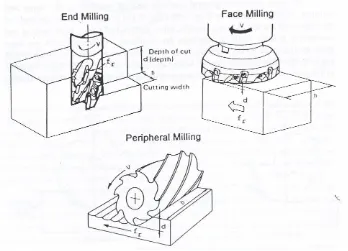
Figure 2.1 Type of milling operation (Stephenson and Agapiou, 1997).
8
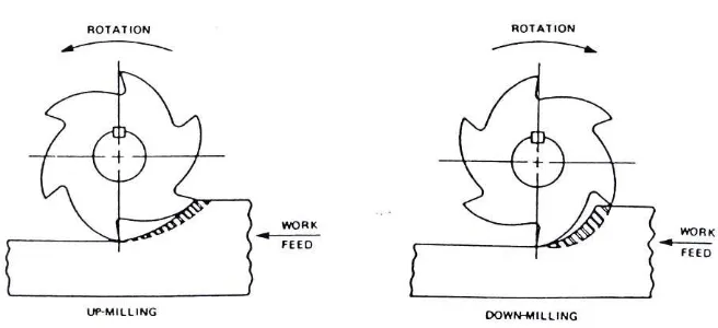
Figure 2.2 Schematic view of the up- and down milling approaches (Stephenson and Agapiou, 1997)
2.2.1 Cutting Force
Cutting forces in milling can be divided into two parts:
• Static or average cutting forces.
• Dynamic or varying instantaneous cutting forces.
For this study only the static cutting force will be observed.
2.2.2 The Static Cutting Force
In determining the work done per tooth and the power requirements, the concept of mean cutting pressure (km) was employed. Schlesinger developed a
9 If cutting is intermittent, whereby one tooth exits the workpiece before the following tooth has entered, then the mean cutting pressure:
π
km = mean cutting pressure (determined from middle chip thickness)
Ft = average or mean tangential force/tooth
v =tangential (peripheral) velocity of the cutter
Ψs = total angle of engagement of the cutter tooth with the workpiece
z = number of teeth in the cutter aa = axial depth of cut
ar = radial depth of cut
fz = feed per tooth
If cutting is continuous, whereby one tooth leaves the cut when the following one takes over, or more teeth than one are cutting at the same time then the mean pressure:
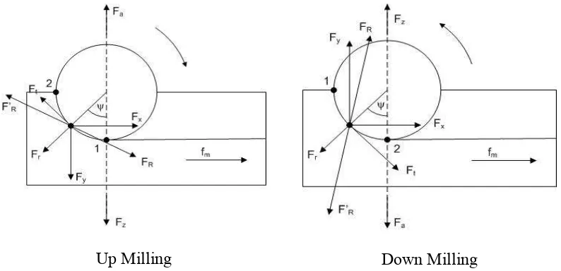
10 2.2.3 Cutting Force in End Milling
The cutting force components acting on one tooth of the end milling cutter are shown in Figure 2.3 (Alauddin, 1993; Alauddin and El-Baradie, 1996; Alauddin et.al., 1996ab).
Up Milling Down Milling
Figure 2.3 Cutting force components acting on one tooth of an end mill (Alauddin, 1993; Alauddin and El-Baradie, 1996; Alauddin et.al., 1996ab).
For the experiments, the average cutting forces in multi-tooth end milling will be used. Although the average cutting force is not the maximum cutting force encountered in an end-milling operation, they are useful to engineers when designing machine tools and setting up the cutting system. In a multi-tooth end milling, if several teeth are cutting simultaneously the total average cutting forces acting on the teeth of the cutter (table system) per cut are