AT Command Set For Nokia CDMA
Products
F O R U M N O K I A
Version 1.1; March 14, 2005
Copyright © 2005 Nokia Corporation. All rights reserved.
Nokia and Nokia Connecting People are registered trademarks of Nokia Corporation. Java and all Java-based marks are trademarks or registered trademarks of Sun Microsystems, Inc. Other product and company names mentioned herein may be trademarks or trade names of their respective owners.
Disclaimer
The information in this document is provided “as is,” with no warranties whatsoever, including any warranty of merchantability, fitness for any particular purpose, or any warranty otherwise arising out of any proposal, specification, or sample. Furthermore, information provided in this document is preliminary, and may be changed substantially prior to final release. This document is provided for informational purposes only.
Nokia Corporation disclaims all liability, including liability for infringement of any proprietary rights, relating to implementation of information presented in this document. Nokia Corporation does not warrant or represent that such use will not infringe such rights.
Nokia Corporation retains the right to make changes to this specification at any time, without notice.
License
Contents
1 Introduction...13
1.1 Description... 13
1.2 AT Command Syntax... 13
1.2.1 Basic commands... 14
1.2.2 S-register commands... 14
1.2.3 Extended commands ... 14
1.2.4 Command line ... 14
1.2.5 Information responses and result codes ... 15
2 Basic Commands ...16
2.1 ATE Command Echo ... 16
2.2 ATL Modem Speaker Volume ... 16
2.3 ATM Monitor Modem Speaker Mode... 16
2.4 ATQ Result Code Suppression ... 17
2.5 ATV Result Code Format ... 17
2.6 ATX Response Range Selection ... 17
2.7 ATZ Reset to Default Configuration ... 18
2.8 AT&C Control Carrier Detect Circuit 109 (CF) ... 18
2.9 AT&D Control Data Terminal Ready Circuit 108/2... 18
2.10 ATT Select Tone Dialing ... 19
2.11 ATP Select Pulse Dialing ... 19
2.12 AT&F Restore to Factory-Defined Configuration ... 19
3 Basic S-Registers ...20
3.1 ATS0 Disable/Enable Automatic Answering ... 20
3.2 ATS2 Escape Code Character... 20
3.3 ATS3 Carriage Return Character... 20
3.4 ATS4 Line Feed Character... 21
3.5 ATS5 Backspace Character ... 21
3.6 ATS6 Pause before Blind Dialing ... 21
3.7 ATS7 Set the Time to Establish an End-to-End Data Connection ... 21
3.8 ATS8 Pause Time for the Comma Dial Modifier ... 22
3.9 ATS9 Carrier Detect Threshold... 22
3.10 ATS10 Number of Tenths of a Second from Carrier Loss ... 22
3.11 ATS11 DTMF Tone Duration and Spacing... 22
4.2 A Enter the Online State ... 24
4.3 D Dialing ... 24
4.4 H Return to Command State ... 25
4.5 O Return to Online State ... 25
5 Extended AT Configuration Commands ...26
5.1 AT+DR Data Compression Reporting... 26
5.2 AT+DS Data Compression... 26
5.3 AT+EB Break Handling in Error Control Operation... 27
5.4 AT+EFCS 32-Bit Frame Check Sequence ... 27
5.5 AT+ER Error Control Reporting ... 28
5.6 AT+ES Error Control Selection ... 28
5.7 AT+ESR Selective Repeat ... 28
5.8 AT+ETBM Call Termination Buffer Management... 29
5.9 AT+GCAP Request Complete Capabilities List ... 29
5.10 AT+GMI Request Manufacturer Identification... 29
5.11 AT+GMM Request Model Identification... 30
5.12 AT+GMR Request Revision Identification... 30
5.13 AT+GSN Request Product Serial Number Identification ... 31
5.14 AT+ICF TE2-MT2 Character Framing ... 31
5.15 AT+IFC TE2-MT2 Local Flow Control ... 32
5.16 AT+ILRR TE2-MT2 Local Rate Reporting... 32
5.17 AT+IPR Fixed Rm Rate ... 33
5.18 AT+MA Modulation Automode Control... 33
5.19 AT+MR Modulation Reporting Control ... 33
5.20 AT+MS Modulation Selection ... 34
5.21 AT+MV18R V.18 Reporting Control... 34
5.22 AT+MV18S V.18 Selection ... 35
6 Facsimile Service Class 2.0 AT Commands ...36
6.1 AT+FAA Adaptive Answer Parameter ... 36
6.2 AT+FAP Addressing and Polling Capabilities Parameter ... 36
6.3 AT+FBO Phase-C Data Bit Order Parameter ... 37
6.4 AT+FBS Buffer Size Parameter... 37
6.5 AT+FBU HDLC Frame Reporting Parameter ... 37
6.6 AT+FCC DCE Capabilities Parameters... 38
6.7 AT+FCLASS Service Class Selection Parameter ... 39
6.8 AT+FCQ Copy Quality Checking Parameter ... 39
6.9 AT+FCR Capability to Receive Parameter ... 39
6.11 AT+FCT DTE Phase-C Timeout Parameter... 41
6.12 AT+FEA Phase-C Received EOL Alignment Parameter ... 41
6.13 AT+FFC Format Conversion Parameter ... 41
6.14 AT+FHS Call Termination Status Parameter... 42
6.15 AT+FIE Procedure Interrupt Enable Parameter... 43
6.16 AT+FIS Current Session Negotiation Parameters... 43
6.17 AT+FLI Local ID String Parameter... 45
6.18 AT+FLO Flow Control Select Parameter ... 45
6.19 AT+FLP Indicate Document to Poll Parameter... 45
6.20 AT+FMS Minimum Phase-C Speed Parameter... 46
6.21 AT+FNR Negotiation Message Reporting Control Parameters... 46
6.22 AT+FNS Non-standard Frame FIF Parameter ... 47
6.23 AT+FPA Selective Polling Address Parameter... 47
6.24 AT+FPI Local Polling ID String Parameter... 47
6.25 AT+FPP Packet Protocol Control Parameter... 47
6.26 AT+FPR Serial Port Rate Control Parameter... 48
6.27 AT+FPS Page Status Parameter... 48
6.28 AT+FPW Password Parameter... 48
6.29 AT+FRQ Receive Quality Threshold Parameters... 49
6.30 AT+FRY ECM Retry Value Parameter... 49
6.31 AT+FSA Subaddress Parameter ... 49
6.32 AT+FSP Request to Poll Parameter ... 49
6.33 AT+FDR Receive Phase-C Data... 50
6.34 AT+FDT Transmit Phase-C Data ... 50
6.35 AT+FIP Initialize Facsimile Parameters ... 50
6.36 AT+FKS Terminate Session ... 50
7 CDMA AT Parameter Commands...51
7.1 AT+CXT Cellular Extension... 51
7.2 AT+CFG Configuration String... 51
7.3 AT+CAD Query Analog or Digital Service ... 51
7.4 AT+CDR Um Interface Data Compression Reporting ... 52
7.5 AT+CDS Um Interface Data Compression ... 52
7.6 AT+CRM Set Rm Interface Protocol ... 53
7.7 AT+CBC Battery Charge... 54
7.8 AT+CQD Command State Inactivity Timer... 54
7.12 AT+CSS Serving System ... 55
7.13 AT+CSQ Query Received Signal Quality ...56
7.14 AT+CSO Service Option ... 57
7.15 AT+CMUX Multiplex Option ... 57
7.16 AT+CFC Um Interface Fax Compression ... 58
8 Cellular Identification AT Command Extensions...59
8.1 AT+CGCAP IWF Content List... 59
8.2 AT+CGMI Request Manufacturer Identification... 59
8.3 AT+CGMM Request Model Identification ... 59
8.4 AT+CGMR Request Revision Identification... 60
8.5 AT+CGOI Request IWF Device Identification ... 60
8.6 AT+CGSN Request Serial Number Identification... 60
9 Cellular AT Commands for Packet Data Services...61
9.1 AT+CTA Set/Read/Test Um Packet Data Inactivity Timer... 61
9.2 AT+CPS Select the Service Option for Packet Data Service ... 61
9.3 AT+CPSR Enable/Disable Packet Call State Reporting ... 61
9.4 AT+CPTC Control Traffic Channel State... 62
9.5 AT+CPER Enable/Disable Packet Call Event Reporting ... 62
10 Nokia Implementation Specific AT Commands...63
10.1 AT+CSP Arrange Mobile Terminated Async Data/Fax Call Service Option... 63
10.2 ATB Communication Protocol... 63
10.3 ATI Request Product Identification Information ... 63
10.4 AT&K Select Flow Control ... 64
10.5 AT&S Data Set Ready Control ... 64
11 AT Commands for Java™ SMS ...65
11.1 AT+CMGS Send an SMS Message... 65
11.2 AT+CMGL Read SMS Messages from Inbox of the SMS_MEMORY Server ... 65
11.3 AT+CMGD Delete an SMS Message from Inbox of the SMS_MEMORY Server... 66
12 AT Commands for Mobile IP ...67
12.1 AT$QCMIP Mobile IP Preferences... 67
12.2 AT$QCMIPP MIP User Profile Selection ... 67
12.3 AT$QCMIPGETP Return Profile Information... 67
12.4 AT$QCMIPNAI Set NAI for Active Profile ... 68
12.5 AT$QCMIPMASS Set MN-AAA Shared Secrets ... 68
12.6 AT$QCMIPMHSS Set MN-HA Shared Secrets ... 68
12.7 AT$QCMIPRT Set Reverse Tunneling ... 69
12.8 AT$QCMIPMASPI Set MN-AAA ... 69
12.10 AT$QCMIPPHA Set the IP Address of the Primary HA... 70
12.11 AT$QCMIPSHA Set the IP Address of the Secondary HA ... 70
12.12 AT$QCMIPHA Set the Mobile Home Address ... 70
12.13 AT+PZID Packet Zone Identification ... 71
12.14 AT$SPNAI Network Access Identifier... 71
13 Nokia Proprietary AT Commands ...72
13.1 AT*T1 Test Mode 1 ... 72
13.2 AT*T2 Test Mode 2 ... 72
13.3 AT*G Life Data Counter Value ... 72
13.4 AT*NOKIAFBUS Activate FBUS ... 72
13.5 AT+WS45 DTE-Side Stack Selection... 73
13.6 AT+WS46 WDE-Side Stack Selection ... 73
13.7 AT$BREW Request Transfer of TE2-MT2 Connection Control to the BREW SIO Command Processor... 73
14 Terms and Abbreviations ...74
15 References ...75
Appendix A Multiplex Options ...76
Tables
Table 2.1: ATE ...16
Table 2.2: ATL ...16
Table 2.3: ATM ...16
Table 2.4: ATQ ...17
Table 2.5: ATV ...17
Table 2.6: ATX ...17
Table 2.7: ATZ ...18
Table 2.8: AT&C...18
Table 2.9: AT&D ...18
Table 2.10: ATT ...19
Table 2.11: ATP...19
Table 2.12: AT&F ...19
Table 3.1: ATS0 ...20
Table 3.2: ATS2 ...20
Table 3.3: ATS3 ...20
Table 3.4: ATS4 ...21
Table 3.5: ATS5 ...21
Table 3.6: ATS6 ...21
Table 3.7: ATS7 ...21
Table 3.8: ATS8 ...22
Table 3.9: ATS9 ...22
Table 3.10: ATS10 ...22
Table 3.11: ATS11 ...22
Table 3.12: ATS12 ...23
Table 4.1: A/ ...24
Table 4.2: A ...24
Table 4.3: D ...24
Table 4.4: H ...25
Table 4.5: O ...25
Table 5.1: AT+DR ...26
Table 5.2: AT+DS...26
Table 5.3: AT+EB...27
Table 5.4: AT+EFCS ...27
Table 5.5: AT+ER...28
Table 5.6: AT+ES ...28
Table 5.8: AT+ETBM ...29
Table 5.9: AT+GCAP...29
Table 5.10: AT+GMI...30
Table 5.11: AT+GMM ...30
Table 5.12: AT+GMR...30
Table 5.13: AT+GSN...31
Table 5.14: AT+ICF ...31
Table 5.15: AT+IFC ...32
Table 5.16: AT+ILRR...32
Table 5.17: AT+IPR...33
Table 5.18: AT+MA ...33
Table 5.19: AT+MR ...33
Table 5.20: AT+MS...34
Table 5.21: AT+MV18R ...34
Table 5.22: AT+MV18S ...35
Table 6.1:AT +FAA ...36
Table 6.2: AT+FAP ...36
Table 6.3: AT+FBO ...37
Table 6.4: AT+FBS...37
Table 6.5: AT+FBU ...37
Table 6.6: AT+FCC ...38
Table 6.7: AT+FCLASS...39
Table 6.8: AT+FCQ...39
Table 6.9: AT+FCR...39
Table 6.10: AT+FCS...40
Table 6.11: AT+FCT...41
Table 6.12: AT+FEA ...41
Table 6.13: AT+FFC...42
Table 6.14: AT+FHS ...42
Table 6.15: AT+FIE ...43
Table 6.16: AT+FIS ...44
Table 6.17: AT+FLI...45
Table 6.18: AT+FLO ...45
Table 6.19: AT+FLP...45
Table 6.20: AT+FMS...46
Table 6.24: AT+FPI ...47
Table 6.25: +FPP...47
Table 6.26: AT+FPR ...48
Table 6.27: AT+FPS ...48
Table 6.28: AT+FPW...48
Table 6.29: AT+FRQ...49
Table 6.30: AT+FRY ...49
Table 6.31: AT+FSA ...49
Table 6.32: AT+FSP ...49
Table 6.33: AT+FDR...50
Table 6.34: AT+FDT ...50
Table 6.35: AT+FIP ...50
Table 6.36: AT+FKS ...50
Table 7.1: AT+CXT...51
Table 7.2: AT+CFG...51
Table 7.3: AT+CAD ...51
Table 7.4: AT+CDR ...52
Table 7.5: AT+CDS...53
Table 7.6: AT+CRM...53
Table 7.7: AT+CBC...54
Table 7.8: AT+CQD ...54
Table 7.9: AT+CRC...54
Table 7.10: AT+CMIP...55
Table 7.11: AT+CBIP...55
Table 7.12: AT+CSS...56
Table 7.13: AT+CSQ ...57
Table 7.14: AT+CSO ...57
Table 7.15: AT+CMUX...58
Table 7.16: AT+CFC...58
Table 8.1: AT+CGCAP...59
Table 8.2: AT+CGMI ...59
Table 8.3: AT+CGMM ...59
Table 8.4: AT+CGMR ...60
Table 8.5: AT+CGOI...60
Table 8.6: AT+CGSN...60
Table 9.1: AT+CTA ...61
Table 9.2: AT+CPS...61
Table 9.4: AT+CPTC...62
Table 9.5: AT+CPER ...62
Table 10.1: AT+CSP ...63
Table 10.2: ATB...63
Table 10.3: ATI...63
Table 10.4: AT&K ...64
Table 10.5: AT&S ...64
Table 11.1: AT+CMGS ...65
Table 11.2: AT+CMGL ...66
Table 11.3: AT+CMGD...66
Table 12.1: AT$QCMIP...67
Table 12.2: AT$QCMIPP ...67
Table 12.3: AT$QCMIPGETP ...67
Table 12.4: AT$QCMIPNAI...68
Table 12.5: AT$QCMIPMASS...68
Table 12.6: AT$QCMIPMHSS...68
Table 12.7: AT$QCMIPRT...69
Table 12.8: AT$QCMIPMASPI ...69
Table 12.9: AT$QCMIPMHSPI ...69
Table 12.10: AT$QCMIPPHA...70
Table 12.11: AT$QCMIPSHA ...70
Table 12.12: AT$QCMIPHA ...70
Table 12.13: AT+PZID ...71
Table 12.14: AT$SPNAI...71
Table 13.1: AT*T1...72
Table 13.2: AT*T2...72
Table 13.3: AT*G...72
Table 13.4: AT*NOKIAFBUS ...72
Table 13.5: AT+WS45 ...73
Table 13.6: AT+WS46 ...73
Table 13.7: AT$BREW ...73
Change History
June 28, 2004 Version 1.0 Initial document release
1 Introduction
1.1 Description
This document lists the attention (AT) commands that can be used with Nokia CDMA products available after spring 2004. These products are the Nokia 3105, Nokia 3125, Nokia 3152, Nokia 3155, Nokia 3155i, Nokia 3205, Nokia 3585i, Nokia 3586, Nokia 3586i, Nokia 3587, Nokia 3587i, Nokia 6012, Nokia 6015, Nokia 6015i, Nokia 6155, Nokia 6155i, Nokia 6225, 6235, Nokia 6235i Nokia 6585, and Nokia 6255 devices.
Figure 1.1: Nokia 6585, Nokia 3205, and Nokia 6255 devices
A short description, the syntax, and the possible setting values are presented for each AT command. The syntax for the AT commands listed in this document conforms with the industry-wide notation. Commands can be given as single commands (for example, AT+CRM=1) or concatenated in a string of commands (for example, AT+CRM=1;+CSO=33). For commands with more than one parameter (for example, AT+FIS=n,n,n,n,n,n,n,n), a comma can be used to skip over a parameter so that its value is not changed. For instance, if +FIS is initially 0,0,0,0,0,0,0,0, issuing “AT+FIS=,,1,,,,,7” changes +FIS to 0,0,1,0,0,0,0,7.
Computers use AT commands to communicate with modems. Most communications applications, however, have a user interface that hides the AT commands from the user. AT commands can be issued via a communications application. When the software in the Nokia product has received an AT command, it responds with a message that is displayed on the screen of the used device, which can also be the mobile device.
The AT commands listed in this document are supported by all Nokia products and all operators.
1.2 AT Command Syntax
The “AT” or “at ” prefix must be added to the beginning of each command line. Several AT commands can be typed on the same line, and in such cases the “AT” or “at” prefix is needed only once, at the beginning of the command line.
1.2.1 Basic commands
A basic command has no ‘+’ prefix. If there is no default value, the setting of that command is not stored in the non-volatile memory.
1.2.2 S-register commands
The existence and values of an S-register command can be queried by giving the command with a question mark (for example, ATS3?).
1.2.3 Extended commands
Extended command have a ‘+’ prefix.
Some extended commands take more than one value (for example, AT+DS=n,n,n,n), and some extended commands take character strings as values instead of numbers (for example AT+MA=<string>).
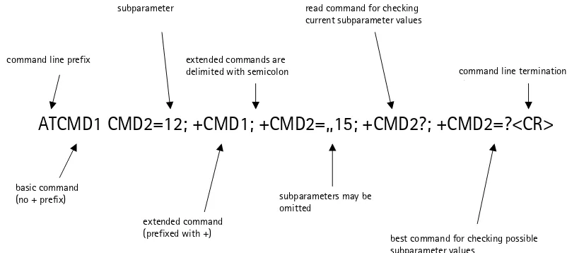
1.2.4 Command line
A command line consists of the Attention code, followed by one or more commands, followed by the end of line code. The Attention code is the character pair “AT” or “at.” By default, the end of line character is the ASCII CR character (decimal 13), unless it is changed by the S3 command. The basic and S-register commands can follow each other on the command line. An extended command must be terminated with a semicolon (;) if another command follows it on a single command line. A semicolon is not required after the last command on the line.
See Figure 1.2 for a basic structure of a command line.
command line prefix
subparameter
extended commands are delimited with semicolon
read command for checking current subparameter values
command line termination h t
basic command (no + prefix)
extended command (prefixed with +)
subparameters may be omitted
best command for checking possible subparameter values
ATCMD1 CMD2=12; +CMD1; +CMD2=,,15; +CMD2?; +CMD2=?<CR>
Figure 1.2: Basic structure of a command line
If verbose responses are enabled with the ATV1 command and all commands in a command line have been successfully performed, the result code <CR><LF>OK<CR><LF> is sent from the terminal adaptor to the terminal equipment. If numeric responses are enabled with the ATV0 command, the result code 0<CR> is sent instead.
If the command syntax is incorrect, an ERROR string is returned.
1.2.5 Information responses and result codes
The terminal adaptor response for the example command line in Figure 1.2 could be as shown in Figure 1.3. In this example, the verbose response format is enabled with the ATV1 command. If the numeric format ATV0 would have been used, <CR><LF> headers of information responses would have been left out and the final result code changed to 0<CR>.
information response to +CMD2=? information response to +CMD2=? also string type subparameters possible
final result code
shows acceptable ranges of each subparameter
<CR><LF> +CMD2:3,0,15,”CDMA”<CR><LF>
<CR><LF> +CMD2:(0-3),(0,1),(0-12,15),(”CDMA”,”IRA”)<CR><LF>
<CR><LF> OK<CR><LF>
Figure 1.3: Response to a command line
2 Basic
Commands
For more information about the basic AT commands and basic AT parameters, see Section 7.1 and 7.1.1 of TIA/EIA/IS-707-A.3 /2/.
2.1 ATE Command Echo
Controls the command character echo in offline command state or online command state.
Syntax Value range Default
value
2.2 ATL Modem Speaker Volume
Controls the modem speaker volume loudness.
Syntax Value range Default
Table 2.2: ATL
2.3 ATM Monitor Modem Speaker Mode
Controls whether the modem speaker is off/on until carrier reported.
Syntax Value range Default
2.4 ATQ Result Code Suppression
Determines whether result codes are returned.
Syntax Value range Default
2.5 ATV Result Code Format
Determines whether the result codes are sent as numbers or words.
Syntax Value range Default
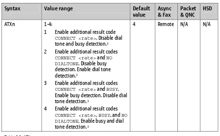
2.6 ATX Response Range Selection
Controls the amount of information in the results code.
Syntax Value range Default
1 Enable additional result code
CONNECT <rate>. Disable dial tone and busy detection.3
2 Enable additional result codes
CONNECT <rate> and NO DIALTONE. Disable busy detection. Enable dial tone detection.3
3 Enable additional result codes
CONNECT <rate> and BUSY. Enable busy detection. Disable dial tone detection. 3
4 Enable additional result codes
CONNECT <rate>, BUSY, and NO DIALTONE. Enable busy and dial tone detection. 3
4 Remote N/A N/A
2.7 ATZ Reset to Default Configuration
Restore the default configuration. The optional parameter “n” is 32 bits.
Syntax Value range Default
0 – 4294967295 (if included): Since only one configuration is
supported, this command always resets back to this default configuration, regardless of the value given.
0 Local &
2.8 AT&C Control Carrier Detect Circuit 109 (CF)
Controls the Carrier Detect circuit 109 (CF).
Syntax Value range Default 1 Circuit 109 (CF) ON in accordance
with the specified service.
1 Local C C
Table 2.8: AT&C
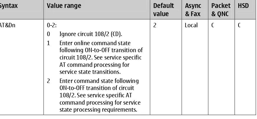
2.9 AT&D Control Data Terminal Ready Circuit 108/2
Controls the Data Terminal Ready circuit 108/2.
Syntax Value range Default
AT&Dn 0-2:
0 Ignore circuit 108/2 (CD). 1 Enter online command state
following ON-to-OFF transition of circuit 108/2. See service specific AT command processing for service state transitions. 2 Enter command state following
ON-to-OFF transition of circuit 108/2. See service specific AT command processing for service state processing requirements.
2 Local C C
2.10 ATT Select Tone Dialing
Selects tone dialing.
Syntax Value range Default
value
Async & Fax
Packet & QNC
HSD
ATT N/A N/A Remote N/A N/A
Table 2.10: ATT
2.11 ATP Select Pulse Dialing
Selects pulse dialing.
Syntax Value range Default
value
Async & Fax
Packet & QNC
HSD
ATP N/A N/A Remote N/A N/A
Table 2.11: ATP
2.12 AT&F Restore to Factory-Defined Configuration
Restores to factory-defined configuration “n,” where n is 32 bits. The effect is implementation dependent.
Syntax Value range Default
value
Async & Fax
Packet & QNC
HSD
AT&Fn (n is optional)
0 – 4294967295 (if included): Since only one configuration is supported, this command always restores back to this factory-defined configuration, regardless of the value given.
0 Local C
(packet only)
N/A
3 Basic
S-Registers
For more information about the basic S-registers, see Section 7.1.2 of TIA/EIA/IS-707-A.3 /2/.
3.1 ATS0 Disable/Enable Automatic Answering
Sets the number of rings before automatic answering. [Enable automatic answering after (Value - 1) x 6 seconds.]
0 Manual answer, automatic answering disabled.
1-10 Automatic answering enabled using this value.
0 Local N/A N/A
Table 3.1: ATS0
3.2 ATS2 Escape Code Character
Stores the code for the Escape code character.
Syntax Value range Default
3.3 ATS3 Carriage Return Character
Stores the code for the Carriage Return character.
3.4 ATS4 Line Feed Character
Stores the code for the Line Feed character.
Syntax Value range Default
3.5 ATS5 Backspace Character
Stores the code for the Backspace character.
Syntax Value range Default
3.6 ATS6 Pause before Blind Dialing
Sets the number of seconds for the pause before blind dialing.
Syntax Value range Default
3.7 ATS7 Set the Time to Establish an End-to-End Data Connection
Sets the number of seconds to establish an end-to-end data connection.
Syntax Value range Default
3.8 ATS8 Pause Time for the Comma Dial Modifier
Sets number of seconds to pause when a “,” is encountered in the dial string.
Syntax Value range Default
3.9 ATS9 Carrier Detect Threshold
Sets the carrier detect threshold in increments of 0.1 seconds.
Syntax Value range Default
3.10 ATS10 Number of Tenths of a Second from Carrier Loss
Sets the number of tenths of a second from carrier loss to disconnect.
Syntax Value range Default
1-254 Enabled, using this value. 255 Disable carrier detect.
14 Remote N/A N/A
Table 3.10: ATS10
3.11 ATS11 DTMF Tone Duration and Spacing
Sets DTMF tone duration and spacing in milliseconds.
Syntax Value range Default
3.12 ATS12 Escape Code Guard Time
Sets the duration of guard time for the escape code sequence in increments of 0.2 seconds.
Syntax Value range Default
value
Async & Fax
Packet & QNC
HSD
ATS12=? ATS12? ATS12=n
0-255 50 Local C/O C/O
4 Basic Action Commands
For more information about the basic action commands, see Section 7.1.3 of TIA/EIA/IS-707-A.3 /2/. See also Section 4.2.3 of IS-707.3 for more detailed information about processing.
4.1 A/ Re-execute Previous Command
Re-executes the previous command.
Syntax Value range Default
Enters the online state. See service specific processing for further details.
Syntax Value range Default
Causes the Mobile Terminal 2 (MT2) to transition from the command state to the online state. The <dial string> is optional. For circuit switched data services, the dial string can contain the following characters: Digits 0 to 9, *, #, A, B, C, and D. The dial string can contain the following dial modifiers:
• T Tone dialing [ignored]
• ; After dialing, the IWF enters the online command state and maintains the connection
Syntax Value range Default
D<dial string> (<dial string> is optional)
N/A N/A Local/
Remote
C C
4.4 H Return to Command State
Causes the MT2 to transition from online command state to command state. Use of the digit ‘0’ is optional (see EIA/TIA-602 /7/).
Syntax Value range Default
value
Async & Fax
Packet & QNC
HSD
H0 (‘0’ is optional) 0 (if included) 0 Remote C/O C/O
Table 4.4: H
4.5 O Return to Online State
Causes the MT2 to transition from online command state to online state. Use of the digit ‘0’ is optional (see EIA/TIA-602 /7/).
Syntax Value range Default
value
Async & Fax
Packet & QNC
HSD
O0 (‘0’ is optional) 0 (if included) 0 Remote O O
5 Extended
AT
Configuration Commands
Extended AT commands are specified in Section 7.2 of TIA/EIA/IS-707-A.3 /2/ and their values in TIA/EIA/IS-131 /8/.
5.1 AT+DR Data Compression Reporting
This extended format numeric parameter controls whether the extended-format “+DR:” intermediate result code is transmitted from the IWF over the Um interface.
Syntax Value range Default
0 Data compression reporting disabled.
1 Data compression reporting enabled.
0 Remote N/A N/A
Table 5.1: AT+DR
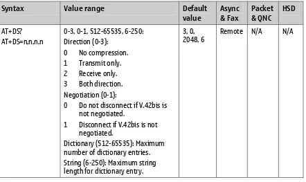
5.2 AT+DS Data Compression
This extended-format compound parameter controls the V.42bis data compression function on the PSTN link if provided in the IWF.
Syntax Value range Default
0-3, 0-1, 512-65535, 6-250: Direction (0-3):
0 No compression. 1 Transmit only. 2 Receive only. 3 Both direction. Negotiation (0-1):
0 Do not disconnect if V.42bis is not negotiated.
1 Disconnect if V.42bis is not negotiated.
Dictionary (512-65535): Maximum number of dictionary entries. String (6-250): Maximum string length for dictionary entry.
3, 0, 2048, 6
Remote N/A N/A
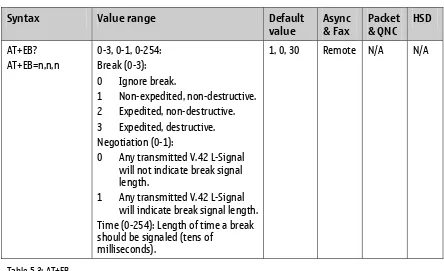
5.3 AT+EB Break Handling in Error Control Operation
This extended-format compound parameter is used to control the manner of V.42 operation on the PSTN link (if present in the IWF).
Syntax Value range Default
1 Non-expedited, non-destructive. 2 Expedited, non-destructive. 3 Expedited, destructive. Negotiation (0-1):
0 Any transmitted V.42 L-Signal will not indicate break signal length.
1 Any transmitted V.42 L-Signal will indicate break signal length. Time (0-254): Length of time a break should be signaled (tens of
milliseconds).
1, 0, 30 Remote N/A N/A
Table 5.3: AT+EB
5.4 AT+EFCS 32-Bit Frame Check Sequence
This extended-format numeric parameter controls the use of the 32-bit frame check sequence option in V.42 on the PSTN link (if present in the IWF). otherwise use 16-bit FCS. 2 Use 32-bit FCS if available,
otherwise disconnect.
1 Remote N/A N/A
5.5 AT+ER Error Control Reporting
This extended-format numeric parameter controls whether the extended-format “+ER:” intermediate result code is transmitted from the IWF over the Um interface.
Syntax Value range Default
0 Disabled 1 Enabled
0 Remote N/A N/A
Table 5.5: AT+ER
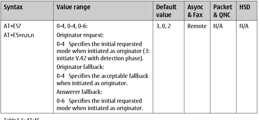
5.6 AT+ES Error Control Selection
This extended-format compound parameter is used to control the manner of operation of the V.42 protocol on the PSTN link (if present in the IWF).
Syntax Value range Default Originator request:
0-4 Specifies the initial requested mode when initiated as originator (3: initiate V.42 with detection phase). Originator fallback:
0-4 Specifies the acceptable fallback when initiated as originator.
Answerer fallback:
0-6 Specifies the initial requested mode when initiated as originator.
3, 0, 2 Remote N/A N/A
Table 5.6: AT+ES
5.7 AT+ESR Selective Repeat
This extended-format numeric parameter controls the use of the selective repeat (SREJ) option in V.42 on the PSTN link (if present in the IWF).
Syntax Value range Default
1 Use SREJ if available, continue if not available.
2 Use SREJ if available, disconnect if not available.
1 Remote N/A N/A
5.8 AT+ETBM Call Termination Buffer Management
This extended-format compound parameter controls the handling of data remaining in IWF buffers upon service termination.
Syntax Value range Default Local terminates call:
0-2 Control how data buffers are handled when local terminates calls. Remote terminates call:
0-2 Control how data buffers are handled when local terminates calls. Timer (0-30):
Maximum time limit to attempt to deliver buffered data.
1, 1, 20 Remote N/A N/A
Table 5.8: AT+ETBM
5.9 AT+GCAP Request Complete Capabilities List
This is a read-only command.
This extended-format command causes the MT2 to transmit one or more lines of information text in a specific format. The content is a list of additional capabilities command +<name>s, which is intended to permit the user of the MT2 to identify the minimum capabilities of the MT2. AT+GCAP is optional in Packet data.
An MT2 conforming to the TIA/EIA/IS-707.3 standard will include the following items, as a minimum, in the result code for the +GCAP command: +CIS707, +MS, +ES, +DS, +FCLASS. The response can also be +CIS707-A if the PRI (516, PRI_RESP_AT_GCAP_COMM) field is turned on. This is due to the fact that a DUN application program (QuickLink Mobile) that Verizon operator uses requires the response for the AT+GCAP to have a “+CIS707-A” response from all 1xRTT capable devices. This feature was made PRI configurable (516) to avoid confusion for the other operators.
Syntax Value range Default value Async & Fax
Packet & QNC
HSD
AT+GCAP N/A (varies depending
on the device)
Local N/A N/A
Table 5.9: AT+GCAP
5.10 AT+GMI Request Manufacturer Identification
This is a read-only command.
Syntax Value range Default value Async & Fax
Packet & QNC
HSD
AT+GMI N/A “Nokia Mobile
Phones”
Local C C
Table 5.10: AT+GMI
5.11 AT+GMM Request Model Identification
This is a read-only command.
This command causes the MT2 to transmit one or more lines of information text, determined by the manufacturer, which is intended to permit the user of the MT2 to identify the specific model of the device. Typically, the text will consist of a single line containing the name of the product, but manufacturers can choose to provide any information desired.
Syntax Value range Default value Async & Fax
Packet & QNC
HSD
AT+GMM N/A (varies depending
on the device)
Local C C
Table 5.11: AT+GMM
5.12 AT+GMR Request Revision Identification
This is a read-only command.
This command causes the MT2 to transmit one or more lines of information text, determined by the manufacturer, which is intended to permit the user of the MT2 to identify the version, revision level or date, or other pertinent information of the device. Typically, the text will consist of a single line containing the version of the product, but manufacturers can choose to provide any information desired.
Syntax Value range Default value Async & Fax
Packet & QNC
HSD
AT+GMR N/A (varies depending
on the device)
Local C C
5.13 AT+GSN Request Product Serial Number Identification
This is a read-only command.
This command causes the MT2 to transmit one or more lines of information text, determined by the manufacturer, which is intended to permit the user of the MT2 to identify the individual device. Typically, the text will consist of a single line containing a manufacturer determined alphanumeric string, but manufacturers can choose to provide any information desired.
Syntax Value range Default value Async & Fax
Packet & QNC
HSD
AT+GSN N/A (varies depending
on the device)
Local C C
Table 5.13: AT+GSN
5.14 AT+ICF TE2-MT2 Character Framing
This extended-format compound parameter is used to determine the local serial port start-stop (asynchronous) character framing that the MT2 will use while accepting Terminal Equipment 2 (TE2) commands and while transmitting information text and result codes to the TE2, if this is not automatically determined (see Section 5.17, “AT+IPR Fixed Rm Rate”).
Syntax Value range Default
value
Async & Fax
Packet & QNC
HSD
AT+ICF=? AT+ICF? AT+ICF=n,n
0 or 3-5, 0-3: Data Format (0, 3-5):
0 Automatically detect start, data, parity, and stop bits.
3 8 Data 1 Stop 4 7 Data 2 Stop
5 7 Data 1 Parity 1 Stop Parity (0-3):
0 Odd 1 Even 2 Mark 3 Space
0, 3 Local C C
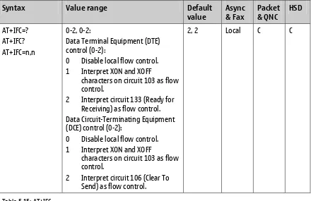
5.15 AT+IFC TE2-MT2 Local Flow Control
This extended-format compound parameter is used to control the operation of local flow control between the TE2 and MT2.
Syntax Value range Default
Data Terminal Equipment (DTE) control (0-2):
0 Disable local flow control. 1 Interpret XON and XOFF
characters on circuit 103 as flow control.
2 Interpret circuit 133 (Ready for Receiving) as flow control. Data Circuit-Terminating Equipment (DCE) control (0-2):
0 Disable local flow control. 1 Interpret XON and XOFF
characters on circuit 103 as flow control.
2 Interpret circuit 106 (Clear To Send) as flow control.
2, 2 Local C C
Table 5.15: AT+IFC
1. See TIA/EIA/IS-707A-3, Table 7.2-1
5.16 AT+ILRR TE2-MT2 Local Rate Reporting
This extended-format numeric parameter controls whether the extended-format +ILPR:<rate> information text is transmitted from the MT2 to the TE2.
Syntax Value range Default
0 Disabled 1 Enabled
0 Local C C
5.17 AT+IPR Fixed Rm Rate
This numeric extended-format parameter specifies the data rate at which the MT2 accepts commands. It can be used to select operation at rates at which the MT2 is not capable of automatically detecting the data rate being used by the TE2.
Syntax Value range Default
When a cable is used: 0 (autobaud), 9600, 14400, 19200, 28800, 38400, 57600, 115200, 230400
When IrDA or Bluetooth used4: 0
(autobaud)
0 Local C C
Table 5.17: AT+IPR
5.18 AT+MA Modulation Automode Control
This extended-format compound parameter is a list of modulations that the base station can use to connect with the remote DCE in Automode operation, for answering or originating data calls, as additional alternatives to the modulation specified in the +MS command.
Syntax Value range Default
Table 5.18: AT+MA
5.19 AT+MR Modulation Reporting Control
This extended-format numeric parameter controls whether the extended-format +MCR:<carrier> and +MRR:<rate> intermediate result codes are transmitted from the IWF to the mobile station.
Syntax Value range Default
0 Disabled 1 Enabled
0 Remote N/A N/A
5.20 AT+MS Modulation Selection
This extended-format compound parameter is used to control the manner of operation of the modulation capabilities in the IWF.
Syntax Value range Default
<string>, (0-1), (0-230400),
(0-230400), (0-230400), (0-230400) Carrier <string>: Prefered modem carrier, IWF specific.
Automode (0-1):
0 Disable automatic modulation negotiation.
1 Enable automatic modulation negotiation.
Min_rate (0-230400) Max_rate (0-230400) Min_rx_rate (0-230400) Max_rx_rate (0-230400)
<string>, 1,0,0,0,0
Remote N/A N/A
Table 5.20: AT+MS
5.21 AT+MV18R V.18 Reporting Control
This extended-format numeric parameter controls whether the extended-format “+MV18R:” result code is transmitted from the IWF to the mobile station.
Syntax Value range Default
0 Disabled 1 Enabled
0 Remote N/A N/A
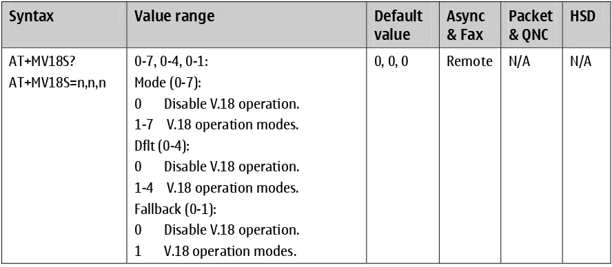
5.22 AT+MV18S V.18 Selection
This extended-format compound parameter is used to control the manner of operation of the V.18 capabilities (if present in the IWF).
Syntax Value range Default
value
Async & Fax
Packet & QNC
HSD
AT+MV18S? AT+MV18S=n,n,n
0-7, 0-4, 0-1: Mode (0-7):
0 Disable V.18 operation. 1-7 V.18 operation modes. Dflt (0-4):
0 Disable V.18 operation. 1-4 V.18 operation modes. Fallback (0-1):
0 Disable V.18 operation. 1 V.18 operation modes.
0, 0, 0 Remote N/A N/A
6 Facsimile
Service
Class 2.0 AT Commands
Facsimile service class 2.0 AT commands are specified in Section 7.3 of TIA/EIA/IS-707-A.3 /2/. For more information, refer to EIA/TIA-592 /9/, TIA/EIA/IS-134 /10/, and Section 4.3.1.2.5 of IS-707.3 /1/.
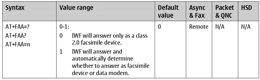
6.1 AT+FAA Adaptive Answer Parameter
See also command +FCLASS in Section 6.7, "AT+FCLASS Service Class Selection Parameter.”
Syntax Value range Default 2.0 facsimile device.
1 IWF will answer and automatically determine whether to answer as facsimile device or data modem.
0 Remote N/A N/A
Table 6.1:AT +FAA
6.2 AT+FAP Addressing and Polling Capabilities Parameter
Indicates the addressing and polling capabilities.
Syntax Value range Default
Subaddressing (0-1): 0 Disable frames. 1 Enable frames. Selective Polling (0-1): 0 Disable polling. 1 Enable polling. Passwords (0-1):
0 Disable passwords. 1 Enable passwords.
0, 0, 0 Remote N/A N/A
6.3 AT+FBO Phase-C Data Bit Order Parameter
Sets the bit transmission order.
Syntax Value range Default
0 Select direct bit order for both phase C and B/D data.
1 Select reversed bit order for phase C and direct bit order for phase B/D data.
2 Select direct bit order for phase C and reversed bit order for phase B/D data.
3 Select reversed bit order for both phase C and B/D data.
0 Remote N/A N/A
Table 6.3: AT+FBO
6.4 AT+FBS Buffer Size Parameter
This is a read-only command.
This command allows the MS to report the size of the MS’s data buffers. The value is in hexadecimal and represents the buffer size in bytes. The MS provides sufficient receive buffer to accommodate three seconds of flow control off at the maximum receive speed; at 9600 bit/s, this is E10h bytes (3600 decimal). The TIA/EIA-592 standard does not mandate a minimum transmit buffer size.
Syntax Value range Default
Transmit buffer size (4092). Receive buffer size (4092).
4092, 4092
Local N/A N/A
Table 6.4: AT+FBS
6.5 AT+FBU HDLC Frame Reporting Parameter
Determines whether to enable or disable HDLC frame reporting.
Syntax Value range Default
0 Disable HDLC frame reporting. 1 Enable HDLC frame reporting.
0 Remote N/A N/A
6.6 AT+FCC DCE Capabilities Parameters
Sets the DCE capabilities.
Syntax Value range Default Vertical-resolution (VR) (0-1): 0 Normal
2 Unlimited length
Data compression format (DF) (0): 0 Modified huffman Error-correction (EC) (0): 0 Disable ECM Binary file transfer (BF) (0): 0 Disable BFT
6.7 AT+FCLASS Service Class Selection Parameter
2.0 Class-2.0 fax service (EIA/TIA-592)
0 Remote N/A N/A
Table 6.7: AT+FCLASS
6.8 AT+FCQ Copy Quality Checking Parameter
Controls the copy quality checking.
Syntax Value range Default
Receive quality checking (0-2): 0 Disable
1-2 Receive quality
Transmit quality checking (0-2): 0 Disable
1-2 Transmit quality
1, 0 Remote N/A N/A
Table 6.8: AT+FCQ
6.9 AT+FCR Capability to Receive Parameter
Determines whether to enable or disable message data reception and remote device polling.
Syntax Value range Default
0 Disable message data reception and remote device polling. 1 Enable message data reception.
0 Remote N/A N/A
6.10 AT+FCS Current Session Results Parameters
This is a read-only command.
Syntax Value range Default Vertical resolution (VR) (0-1): 0 Normal
2 Unlimited length
Data compression format (DF) (0): 0 Modified huffman Error correction (EC) (0): 0 Disable ECM Binary file transfer (BF) (0): 0 Disable BFT
6.11 AT+FCT DTE Phase-C Timeout Parameter
Determines DTE Phase-C timeout in seconds.
Syntax Value range Default
value
Async & Fax
Packet & QNC
HSD
AT+FCT=? AT+FCT? AT+FCT=n
0-255 30 Remote N/A N/A
Table 6.11: AT+FCT
6.12 AT+FEA Phase-C Received EOL Alignment Parameter
Determines byte-alignment of EOL in received T.4 data streams.
Syntax Value range Default
value
Async & Fax
Packet & QNC
HSD
AT+FEA=? AT+FEA? AT+FEA=n
0-1:
0 Determine that T.4 EOL patterns are bit aligned.
1 Determine that the last received bits of T.4 EOL pattern are byte aligned.
0 Remote N/A N/A
Table 6.12: AT+FEA
6.13 AT+FFC Format Conversion Parameter
Syntax Value range Default value
Async & Fax
Packet & QNC
HSD
AT+FFC=? AT+FFC? AT+FFC=n,n,n,n
0-3, 0-2, 0-3, 0-2:
0 Vertical resolution (0-3): 1 Codes ignored
2 Checking enabled
3 Conversion enabled for 1-D data 4 Conversion enabled for 2-D data Data format (0-2):
0 Codes ignored 1 Checking enabled 2 Conversion enabled Page length (0-3):
0 Codes ignored 1 Checking enabled
2 Conversion enabled for 1-D data 3 Conversion enabled for 2-D data Page width (0-2):
0 Codes ignored 1 Checking enabled 2 Conversion enabled
0, 0, 0, 0 Remote N/A N/A
Table 6.13: AT+FFC
6.14 AT+FHS Call Termination Status Parameter
Sets the call termination status.
Syntax Value range Default
value
Async & Fax
Packet & QNC
HSD
AT+FHS? 0-255:
0 Normal connection termination.
1-255 Hangup status.
0 Remote N/A N/A
6.15 AT+FIE Procedure Interrupt Enable Parameter
Determines whether to ignore or accept remote procedure interrupts.
Syntax Value range Default
value
Async & Fax
Packet & QNC
HSD
AT+FIE=? AT+FIE? AT+FIE=n
0-1:
0 Ignore remote procedure interrupts.
1 Accept remote procedure interrupts.
0 Remote N/A N/A
Table 6.15: AT+FIE
6.16 AT+FIS Current Session Negotiation Parameters
Syntax Value range Default Vertical resolution (VR) (0-1): 0 Normal
2 Unlimited length
Data compression format (DF) (0): 0 Modified huffman Error correction (EC) (0): 0 Disable ECM Binary file transfer (BF) (0): 0 Disable BFT
6.17 AT+FLI Local ID String Parameter
This command is used for TSI or CSI.
Syntax Value range Default
Table 6.17: AT+FLI
6.18 AT+FLO Flow Control Select Parameter
Selects the flow control option.
Syntax Value range Default 1 Software flow control
(XON/XOFF).
2 Hardware Flow control.
2 Local N/A N/A
Table 6.18: AT+FLO
6.19 AT+FLP Indicate Document to Poll Parameter
Indicates whether the DTE has a document to poll.
Syntax Value range Default document to poll.
1 Indicate that the DTE has a document ready to poll.
0 Remote N/A N/A
6.20 AT+FMS Minimum Phase-C Speed Parameter
Sets the minimum phase-C speed.
Syntax Value range Default
Table 6.20: AT+FMS
6.21 AT+FNR Negotiation Message Reporting Control Parameters
Controls the negotiation message reporting.
Syntax Value range Default
Receive parameter reporting (0-1): 0 Receive parameters are not
reported.
1 Receive parameters are reported.
Transmitter parameter reporting (0-1):
0 Transmit parameters are not reported.
1 Transmit parameters are reported.
ID string reporting (0-1): 0 ID strings are not reported. 1 ID strings are reported.
Non-standard frames reporting (0-1): 0 Non-standard frames are not
reported.
1 Non-standard frames are reported.
0, 0, 0, 0 Remote N/A N/A
6.22 AT+FNS Non-standard Frame FIF Parameter
Sets the non-standard frame FIF.
Syntax Value range Default
Table 6.22: AT+FNS
6.23 AT+FPA Selective Polling Address Parameter
Sets the selective polling address sent to the remote fax machine.
Syntax Value range Default
Table 6.23: AT+FPA
6.24 AT+FPI Local Polling ID String Parameter
Sets the local polling ID.
Syntax Value range Default
Table 6.24: AT+FPI
6.25 AT+FPP Packet Protocol Control Parameter
This is a read-only command.
6.26 AT+FPR Serial Port Rate Control Parameter
Controls the serial port rate.
Syntax Value range Default
Table 6.26: AT+FPR
6.27 AT+FPS Page Status Parameter
Sets the page status.
Syntax Value range Default
2 Page bad, retrain requested. 3 Page good, retrain requested. 4 Page bad, interrupt requested. 5 Page good, interrupt requested.
1 Remote N/A N/A
Table 6.27: AT+FPS
6.28 AT+FPW Password Parameter
This command is used for sending or polling.
Syntax Value range Default
6.29 AT+FRQ Receive Quality Threshold Parameters
The first parameter specifies the percentage of good lines and the second parameter specifies the maximum tolerable number of consecutive bad lines.
Syntax Value range Default
Percentage of good lines (0-100). Maximum number of consecutive bad lines (0-255).
0, 0 Remote N/A N/A
Table 6.29: AT+FRQ
6.30 AT+FRY ECM Retry Value Parameter
Defined in units of four retries.
Syntax Value range Default
Table 6.30: AT+FRY
6.31 AT+FSA Subaddress Parameter
Sets the destination subaddress sent to the remote fax machine.
Syntax Value range Default
Table 6.31: AT+FSA
6.32 AT+FSP Request to Poll Parameter
Indicates whether the DTE wants to allow polling.
Syntax Value range Default receive a polled document.
6.33 AT+FDR Receive Phase-C Data
Initiates transition to Phase-C data reception.
Syntax Value range Default
value
Async & Fax
Packet & QNC
HSD
AT+FDR N/A N/A Remote N/A N/A
Table 6.33: AT+FDR
6.34 AT+FDT Transmit Phase-C Data
Requests the DCE to transmit Phase-C data.
Syntax Value range Default
value
Async & Fax
Packet & QNC
HSD
AT+FDT N/A N/A Remote N/A N/A
Table 6.34: AT+FDT
6.35 AT+FIP Initialize Facsimile Parameters
Causes the DCE to initialize all the parameters to the default settings.
Syntax Value range Default
value
Async & Fax
Packet & QNC
HSD
AT+FIP=n (n is optional)
0 0 Remote N/A N/A
Table 6.35: AT+FIP
6.36 AT+FKS Terminate Session
Terminates the session.
Syntax Value range Default
value
Async & Fax
Packet & QNC
HSD
AT+FKS N/A N/A Remote N/A N/A
7 CDMA AT Parameter Commands
These cellular extensions AT commands are specified in Section 7.4 of TIA/EIA/IS-707-A.3 /2/.
7.1 AT+CXT Cellular Extension
Defines what is to be done with unrecognized AT commands.
Syntax Value range Default
0 Do not pass unrecognized commands to the IWF. 1 When detecting an
unrecognized AT command, open transport layer connection and pass the unrecognized command to the IWF.
0 Local N/A N/A
Table 7.1: AT+CXT
7.2 AT+CFG Configuration String
The string (up to and including the termination character) will be stored by the MT2 and sent to the base station prior to dialing. Each transmission of an AT+CFG command from the TE2 replaces the contents of the previous string. The string can be up to 248 characters.
Syntax Value range Default
Table 7.2: AT+CFG
7.3 AT+CAD Query Analog or Digital Service
This is a read-only command.
Syntax Value range Default
AT+CAD? 0-255:
0 If no service is available. 1 If CDMA Digital service available. 2 If TDMA Digital service available. 3 If Analog service is available. (values 4-255 reserved)
N/A Local C C
7.4 AT+CDR Um Interface Data Compression Reporting
This extended-format numeric parameter controls whether the extended-format “+CDR:” intermediate result code is transmitted by the MT2. The result code is the same as for the TIA/EIA/IS-131 +DR result code.
Syntax Value range Default
value
Async & Fax
Packet & QNC
HSD
AT+CDR=? AT+CDR? AT+CDR=n
0-1:
0 Disable data compression reporting. Do not issue +CDR result codes.
1 Enable data compression reporting. Issue +CDR.
0 Local N/A N/A
Table 7.4: AT+CDR
7.5 AT+CDS Um Interface Data Compression
Syntax Value range Default
0-3, 0-1, 512-32768, 6-250: Direction (0-3):
0 Disable compression (V.42 bis). 1 If the MS supports data
compression, enable compression MS to BMI DCE. 2 If the MS supports data
compression, enable compression BMI DCE to MS. 3 If the MS supports data
compression, enable
compression in both directions between MS and DCE.
Negotiation (0-1):
0 If compression direction is not as requested, do not
disconnect.
1 If compression direction is not as requested, disconnect. Max_dict (512-32768): Maximum size of dictionary in octets (V.42 bis P1).
<max_dict> applies between BMI DCE and far-end DCE.
Max_string (6-250): Maximum number of characters that can be compressed into one word (V.42 bis P2). <max_string> applies between
BMI DCE and far-end DCE.
0, 0, 512, 32
Local N/A N/A
Table 7.5: AT+CDS
7.6 AT+CRM Set Rm Interface Protocol
See reference /1/ for a description of the +CSO, +CRM, +CMUX, and +CPS AT commands’ interaction.
Syntax Value range Default
0 Asynchronous Data or Fax. 1 Packet data service, relay
model.
2 Packet data service, network model.
0 Local C C
7.7 AT+CBC Battery Charge
This is a read-only command.
Syntax Value range Default
Battery charge status (BCS) (0-3): 0 MT2 powered by battery, BCL =
charge level.
1 MT2 connected to external power.
2 Battery status not available. 3 Recognized power fault. Calls
inhibited.
Battery charge level (BCL) (0-100): 0-100 Battery capacity range is 0-100%
N/A Local C C
Table 7.7: AT+CBC
7.8 AT+CQD Command State Inactivity Timer
Sets the number of seconds after which a call will be released if there is no activity.
Syntax Value range Default
1-255 Release call after 5x<value> seconds have elapsed without activity.
10 (50 s) Remote N/A N/A
Table 7.8: AT+CQD
7.9 AT+CRC Cellular Result Codes
Determines whether to enable or disable cellular result codes.
Syntax Value range Default
7.10 AT+CMIP Mobile Station IP Address
This is a read-only command.
Returns the mobile station’s temporary IP address.
Syntax Value range Default
value
Async & Fax
Packet & QNC
HSD
AT+CMIP? N/A N/A Local N/A N/A
Table 7.10: AT+CMIP
7.11 AT+CBIP Base Station IP Address
This is a read-only command.
Returns the base station’s IP address.
Syntax Value range Default
value
Async & Fax
Packet & QNC
HSD
AT+CBIP? N/A N/A Local N/A N/A
Table 7.11: AT+CBIP
7.12 AT+CSS Serving System
This is a read-only command.
Note: P_REV_IN_USE is added per 3GPP2 contribution. It is not required for release 0 but it is preferred to adopt in release 0. It’s also required by some carriers, see “Adding a PREV field in the +CSS? AT command” /6/.
Syntax Value range Default
AT+CSS? 0-2,<Band>,<SID>,<P_REV_IN_USE> Band Class (0-2):
0 The current band class is unsupported by this command. 1 Band Class 0 (e.g. 800 MHz
Cellular) is supported.
2 Band Class 1 (e.g. 1900 MHz PCS) is supported.
Band:
A-F If the band is x, the mobile station is registered with an x-band system under the band class specified in <Band Class>. Z The mobile station is not registered.
SID:
0-16383 The mobile station is registered with the system indicated. 99999 The mobile station is not registered.
P_REV_IN_USE: 5
0 For unrecognized system or Non-CDMA systems
1 IS-95 or J-STD-008 2 IS-95-A 3 IS-95-A + TSB74 4 TIA/EIA-95-B 5 TIA/EIA-95-B 6 IS-2000 7 IS-2000-A 8 IS-2000-B 9 IS-2000-C 10 IS-2000-C
N/A Local C C
Table 7.12: AT+CSS
7.13 AT+CSQ Query Received Signal Quality
This is a read-only command.
Returns the Signal Quality Measure <SQM> and the Frame Error Rate <FER>.
5
Syntax Value range Default
Signal Quality Measure (SQM) (0-31 or 99):
0-31 Signal Quality Measurement6
99 SQM is not known or is not detectable.
All other values are reserved.
Frame Error Rate (FER) (0-7 or 99):
All other values are reserved.
N/A Local C C
Table 7.13: AT+CSQ
7.14 AT+CSO Service Option
The values for this field vary depending on the value of +CRM. (See reference /1/ for a description of the +CSO, +CRM, +CMUX, and +CPS AT commands’ interaction.)
Syntax Value range Default
Table 7.14: AT+CSO
7.15 AT+CMUX Multiplex Option
Syntax Value range Default value
Async & Fax
Packet & QNC
HSD
AT+CMUX=? AT+CMUX? AT+CMUX=n (if +CRM=0) or AT+CMUX=n,n (if +CRM=1 or 2)
Refer to Appendix A, “Multiplex Options.”
Refer to Appendix A,
“Multiplex Options.”
Local C C
Table 7.15: AT+CMUX
7.16 AT+CFC Um Interface Fax Compression
Sets the form of compression.
Syntax Value range Default
value
Async & Fax
Packet & QNC
HSD
AT+CFC=? AT+CFC? AT+CFC=n
0-1:
0 No compression. 1 V.42bis compression with
parameters as set by the +CDS command.
0 Local N/A N/A
8 Cellular Identification AT Command Extensions
These cellular identification at command extensions are specified in Section 7.4 of TIA/EIA/IS-707-A.3 /2/ and their values in TIA/EIA/IS-131 /8/.
8.1 AT+CGCAP IWF Content List
This extended-format command causes the IWF to transmit one or more lines of information text in a specific format. The content is a list of additional capabilities command +<name>s, which is intended to permit the user of the IWF to identify the minimum capabilities of the IWF. IWFs conforming to the TIA/EIA/IS-707.3 standard will include the following items, as a minimum, in the result code for the +CGCAP command: +CIS707, +MS, +ES, +DS, and +FCLASS.
Syntax Value range Default
Table 8.1: AT+CGCAP
8.2 AT+CGMI Request Manufacturer Identification
This command causes the IWF to transmit one or more lines of information text, determined by the manufacturer, which is intended to permit the user of the IWF to identify the manufacturer. Typically, the text will consist of a single line containing the name of the manufacturer, but manufacturers can choose to provide more information if desired (for example,, address or telephone number for customer service).
Syntax Value range Default
Table 8.2: AT+CGMI
8.3 AT+CGMM Request Model Identification
This command causes the IWF to transmit one or more lines of information text, determined by the manufacturer, which is intended to permit the user of the IWF to identify the specific model of the device. Typically, the text will consist of a single line containing the name of the product, but manufacturers can choose to provide any information desired.
Syntax Value range Default
8.4 AT+CGMR Request Revision Identification
This command causes the IWF to transmit one or more lines of information text, determined by the manufacturer, which is intended to permit the user of the IWF to identify the version, revision level or date, or other pertinent information of the device. Typically, the text will consist of a single line containing the version of the product, but manufacturers can choose to provide any information desired.
Syntax Value range Default
value
Async & Fax
Packet & QNC
HSD
AT+CGMR N/A N/A Remote N/A N/A
Table 8.4: AT+CGMR
8.5 AT+CGOI Request IWF Device Identification
This command causes the IWF to transmit one or more lines of information text, determined by the manufacturer, which is intended to permit the user of the IWF to identify the device, based on the ISO system for registering unique object identifiers. Typically, the text will consist of a single line
containing numeric strings delimited by period characters.
Syntax Value range Default
value
Async & Fax
Packet & QNC
HSD
AT+CGOI N/A N/A Remote N/A N/A
Table 8.5: AT+CGOI
8.6 AT+CGSN Request Serial Number Identification
This command causes the IWF to transmit one or more lines of information text, determined by the manufacturer, which is intended to permit the user of the IWF to identify the individual device. Typically, the text will consist of a single line containing an alphanumeric string defined by the manufacturer, but manufacturers can choose to provide any information desired.
Syntax Value range Default
value
Async & Fax
Packet & QNC
HSD
AT+CGSN N/A N/A Remote N/A N/A
9 Cellular AT Commands for Packet Data Services
These cellular AT commands for packet data services are specified in Section 7.4 of TIA/EIA/IS-707-A.3 /2/.
9.1 AT+CTA Set/Read/Test Um Packet Data Inactivity Timer
Sets the time for observed inactivity in a packet data connection before release of the traffic channel.
Syntax Value range Default
0 Traffic Channel not released during inactivity periods. 20-255 Release the Traffic Channel after <value> 1-second intervals have elapsed since last sending or
receiving Radio Link Protocol (RLP) data frames on the Um interface.
20 N/A C C
Table 9.1: AT+CTA
9.2 AT+CPS Select the Service Option for Packet Data Service
Values are as specified in TSB58 /11/. (See reference /1/ for a description of the +CSO, +CRM, +CMUX, and +CPS AT commands’ interaction.)
Syntax Value range Default
Table 9.2: AT+CPS
9.3 AT+CPSR Enable/Disable Packet Call State Reporting
Determines whether to enable or disable packet call state reporting.
Syntax Value range Default
0 Disables call state reporting. 1 Enables call state reporting.
0 N/A C C
9.4 AT+CPTC Control Traffic Channel State
Controls the Traffic Channel state without affecting the IWF Link Layer connection.
Syntax Value range Default
value
Async & Fax
Packet & QNC
HSD
AT+CPTC=? AT+CPTC? AT+CPTC=n
0-1:
0 Release Traffic Channel. 1 Originate Traffic Channel.
0 N/A C C
Table 9.4: AT+CPTC
9.5 AT+CPER Enable/Disable Packet Call Event Reporting
Determines whether to enable or disable packet call event reporting.
Syntax Value range Default
value
Async & Fax
Packet & QNC
HSD
AT+CPER=? AT+CPER? AT+CPER=n
0-1:
0 Disables call event reporting. 1 Enables call event reporting.
0 N/A C C
10 Nokia Implementation Specific AT Commands
10.1 AT+CSP Arrange Mobile Terminated Async Data/Fax Call Service Option
Determines how the mobile station interprets the incoming call.
Syntax Value range Default
0 Do not reinterpret the incoming call, let the call proceed as normal.
1 Interpret the incoming call as a Async Data call.
2 Interpret the incoming call as a Fax call.
0 Local N/A N/A
Table 10.1: AT+CSP
10.2 ATB Communication Protocol
No actions are associated with the implementation of this command. This command just returns OK.
Syntax Value range Default
10.3 ATI Request Product Identification Information
Requests product identification information.
Syntax Value range Default