1295
Hybrid Multi-scale Basalt Fiber-epoxy Composite Laminate Reinforced with
Electrospun Polyurethane Nanofibers Containing Carbon Nanotubes
I. D. G. Ary Subagia1, Zhe Jiang2, Leonard D. Tijing3, Yonjig Kim4,5*, Cheol Sang Kim2,4, Jae Kyoo Lim4,5, and Ho Kyong Shon3
1
Mechanical Engineering, Faculty of Udayana University, Denpasar, Bali, Indonesia
2
Department of Bionanosystem Engineering, Graduate School, Chonbuk National University, Jeonju 561-756, Korea
3
School of Civil and Environmental Engineering, University of Technology, Sydney (UTS), P.O. Box 123, Broadway, NSW 2007, Australia
4
Division of Mechanical Design Engineering, Chonbuk National University, Jeonju 561-756, Korea
5
Advanced Wind Power System Research Center, Chonbuk National University, Jeonju 561-756, Korea
(Received September 10, 2013; Revised December 12, 2013; Accepted January 4, 2014)
Abstract: In this study, we report the fabrication and evaluation of a hybrid multi-scale basalt fiber/epoxy composite laminate reinforced with layers of electrospun carbon nanotube/polyurethane (CNT/PU) nanofibers. Electrospun polyurethane mats containing 1, 3 and 5 wt% carbon nanotubes (CNTs) were interleaved between layers of basalt fibers laminated with epoxy through vacuum-assisted resin transfer molding (VARTM) process. The strength and stiffness of composites for each configuration were tested by tensile and flexural tests, and SEM analysis was conducted to observe the morphology of the composites. The results showed increase in tensile strength (4-13 %) and tensile modulus (6-20 %), and also increase in flexural strength (6.5-17.3 %) and stiffness of the hybrid composites with the increase of CNT content in PU nanofibers. The use of surfactant to disperse CNTs in the electrospun PU reinforcement resulted to the highest increase in both tensile and flexural properties, which is attributed to the homogeneous dispersion of CNTs in the PU nanofibers and the high surface area of the nanofibers themselves. Here, the use of multi-scale reinforcement fillers with good and homogeneous dispersion for epoxy-based laminates showed increased mechanical performance of the hybrid composite laminates.
Keywords: Basalt fiber, Mechanical properties, Electrospinning, Polyurethane, Carbon nanotubes
Introduction
In recent years, fiber reinforced polymer (FRP) composite has become extremely popular in engineering and technology [1], and is applied in many fields for components in aircraft, spacecraft, ships, automobiles, civil infrastructure, sporting goods, consumer products [2,3], and even in biomedical devices [4]. The rise in FRP popularity gained momentum because of its good density, high specific stiffness and specific strength, good fatigue endurance, excellent corrosion resistance, outstanding thermal insulation, and low thermal expansion [5]. In the continued effort to enhance the properties of FRP composites, many research groups have sought out different techniques such as modifying the production method, surface modification of reinforcing fibers [6], and incorporation of nanoparticles [7,8] and nanofibers [9]. However, more stringent environmental laws have driven research to the use of natural fibers as reinforcements. In this regard, basalt fiber has gained increasing interest as a reinforcing filler to composites as an alternative to glass [10] and carbon [11] fibers due to its many advantages in terms of cost, physical, mechanical, and chemical properties, and being environmentally-friendly [12]. Yet, basalt has still lower overall mechanical and physical properties compared to carbon fiber, thus the resulting composite laminate from
basalt fiber reinforcement alone is still inferior to carbon fiber reinforced laminate [13]. To further enhance the properties of a fiber-reinforced polymer, multiple reinforcement length scales are being developed and studied by many research groups [14-17]. The emergence of polymer nanocomposite has become a main factor supporting the rise of quality and structural performance capability of basalt fiber as a reinforcing material for polymer [18,19]. Recently, interleaving of nanofibrous layers in the FRP has gained interest, wherein the nanofibers where fabricated by an electrospinning technique. Electrospinning is an easy, versatile and scalable way of producing ultrafine nanofibers by the application of a high electric field [20-22]. The fiber is produced in a size range of a few microns to nano scale. The advantages of using electrospinning are its low cost for fabrication, high surface-area-to-volume ratio, easy combination with different fibers [23,24], flexibility in surface functionalities, and superior stiffness and tensile strength [25].
epoxy laminates [12]. The authors reported a considerable enhancement of interlaminar fracture toughness of the carbon/epoxy composites even at a low PEK-C nanofiber weight loading of 0.4 %. However, based from the current literature, most of the nanofiber reinforcement for FRP were in the neat polymer nanofiber state, i.e., only nanofibers were incorporated in the fiber-epoxy matrix, mostly carbon fiber-based composites. The effect of addition of nanoparticles inside the nanofiber as a further reinforcement strategy could provide better resulting mechanical properties, and is ought to be investigated. In this study, we incorporated electrospun polyurethane (PU) nanofibers in a basalt fiber-epoxy laminate. The PU nanofibers were incorporated with different concen-trations of carbon nanotubes with and without surfactant. Here, PU was chosen because it is one of the widely used polymers due to its excellent mechanical and thermal properties, good abrasion resistance and fatigue life, and also water insolubility [32]. Many research studies have explored the use of electrospun polyurethane nanofibers as a constituent of composites material including the incorporation of nanoparticles to impart functionality to the nanofibers [33, 34]. Among nanoparticle reinforcements, carbon nanotubes (CNTs) stand out as nanofiller because of their high aspect ratio, very low density, small size and excellent mechanical and electrical properties [35].
To the authors’ best knowledge, no one has reported yet the use of electrospun CNT/PU nanofibers as reinforcement to basalt fiber-reinforced epoxy laminate. In this study, we investigated the effect of the CNT concentration and the PU nanofiber reinforcement on the tensile and flexural properties of the composite laminate fabricated by VARTM. Tensile and flexural testing (three point bending) were conducted to investigate the effect of electrospun CNT/PU neat with different weight fractions toward the mechanical properties of composites. The fracture surface of composites were also
studied by scanning electron microcope (SEM) to assess the toughening mechanism due to the thin electrospun CNT/PU nanofibers and the possible interaction between the basalt fiber, epoxy matrix, and electrospun CNT/PU nanofibers.
Experimental
Materials
Plain woven basalt fibers (EcoB4 F210) supplied by Seco-Tech. (Korea), with a weight 210±10 g/m2 and thickness 0.19±0.20 mm were used as reinforcement of the composites without surface modification. Epoxy resin (HTC-667C) was used with specific gravity=1.16±0.02 and viscosity=1200± 500 cps which includes a modified aliphatic amine hardener produced by Jet Korea Co. (Korea). High molecular weight thermoplastic polyurethane (PU) was provided by Lubrizol Advanced Materials, Inc. Methyl ethyl ketone (MEK), and acetone and N,N-dimethylformamide (DMF) were purchased from Junsei Chemical Co. Ltd., Japan and Showa Chemical Co., Ltd., Japan, respectively. Triton X-100 was used as surfactant and was bought from OCI Company. All reagents were used without any further purification. Multi-walled CNTs with an average diameter of 11 nm, length=10-30 µm,
and purity >95 % were used which were synthesized by chemical vapor deposition (CVD) and were provided by Nanosolutions, Inc. (Korea).
Electrospinning
To prepare the CNT/PU solutions, different CNT concen-trations (i.e., 1, 3, and 5 wt%) based from the weight of PU were added to 10 wt% PU in DMF/MEK (50/50, wt/wt%) solution. Prior to mixing in PU solution, CNT in DMF/MEK were bath sonicated (40 Hz, Mujigae, Korea) for 1 h. Another solution containing 3 wt% CNT/DMF/MEK solution was added with surfactant Triton-X in the ratio of 1:5 (CNT:
Triton-X, wt/wt%), to study the effect of surfactant in the dispersion of CNT and its subsequent effect to the mechanical property enhancement of the composite.
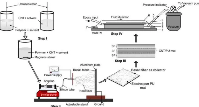
Electrospinning was carried out in the set-up described in a previous report [36]. A high voltage of 15 kV was applied to the electrospinning solution inside a plastic syringe at a feed rate of 1 ml/h. The distance of needle tip and a flat aluminum collector covered with basalt fiber layer (size of 25×25 mm) was kept constant at 150 mm (see Figure 1). The sealed chamber humidity was kept at 30 %. After electro-spinning, the nanofibers attached on basalt fiber layers were dried at 60oC for 48 h in an oven to remove residual solvents.
Fabrication of Hybrid Composite Laminate by VARTM Figure 1 shows the design and fabrication process of the present hybrid composite laminates. In this study, twelve plies of basalt fiber layer laminates with area of ~500 mm2 with or without two plies of CNT/PU electrospun nanofibrous layer interleaved between them were prepared and fabricated by a vacuum assisted resin transfer molding (VARTM) process [37]. Table 1 shows the components, concentration, and names of the different samples prepared in this study. Before the lamination process, the neat PU or CNT/PU nanofibers were directly electrospun to basalt fiber layers and were arranged accordingly in the composite laminates. The arranged layers of basalt and nanofibrous mats were then wrapped with plastic bag using a sealant tape (AT200Y, General Sealants Inc., USA) stacked on square stainless steel plate with a size of 300×300 mm2. Mixture of epoxy resin and hardener, which was degassed beforehand using a dessicator, was then injected at a ratio of 5:1 into the mold at a pressure of −80 kPa for 45 minutes through a vacuum
pump (Airtech Ulvac G-100D). The prepared panel (i.e., molded material) was cured in an autoclave at 65oC for 2 h.
Measurements and Characterization
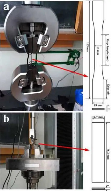
The specimens were cut by water jet from the fabricated panels. Figure 2 shows the schematic layout of the specimen for tensile (Figure 2(a)) and flexural (Figure 2(b)) tests. The tensile test and flexural test were conducted according to ASTM D 638 and ASTM D 790 [38,39], respectively. Five specimens from each neat and hybrid composite laminate sample were tested. Tensile testing was carried out using a universal testing machine (Unitect-M, R&B) at a constant crosshead speed of 1 mm/min. The strain was measured through an extensometer with a gage length of 50 mm (Epsilon Tech. Corp. Model 3542). Flexural testing was done by a three point bending test, with a support span length of 32 mm. A 1 mm/min constant strain rate was maintained in the flexural test until failure of the specimen. Here, the flexural strength of the sample is the highest stress prior to failure, and flexural modulus is obtained from the slope of the straight-line portion of the stress-strain curve [40]. The average values from five tests for each specimen and their standard deviations are reported in this study. To help support the mechanical test results, scanning electron microscopy (SEM, Jeol, Japan) was carried out to the surface and cross-section of the neat and composite laminates, as well as on the nanofibers.
Results and Discussion
Characterization
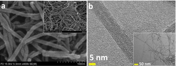
Figure 3 shows the FE-SEM and TEM images of the CNTs used in the present study. The CNTs showed smooth surface with about six concentric layers. The average diameter of the CNTs was 11 nm, which make them much smaller Figure 2. Placement, design and dimension of specimens for (a)
tensile and (b) flexural tests.
Table 1. Name convention and components of the present neat BFRP and hybrid composite laminates
Specimen Configuration
BFRP BF/Epoxy (HTC-667C) BPC-1 BF+1 wt% CNT/PU nanofibers BPC-2 BF+3 wt% CNT/PU nanofibers BPC-3 BF+5 wt% CNT/PU nanofibers
than the electrospun fibers, thus making them as good filler materials. Proper dispersion of CNTs is important to enable a good load transfer from the polymer to the CNTs, resulting to improved properties of the composite. In the present study, the CNTs were dispersed in a solvent solution and were subjected to bath sonication for one hour. Before electrospinning, the CNT/DMF/MEK solutions with different CNT contents were left untouched for at least 2 days to check the dispersion of the CNTs. We found that the addition of Triton-X surfactant has aided in the better dispersion of CNTs without much visible agglomeration and settling down (results not shown). The other solutions with varying CNT contents and without surfactant showed some agglomerations especially at the higher CNT content of 5 wt%. To lessen the agglomeration during electrospinning, we made sure that each CNT solution was sonicated for at least 15 min right before electrospinning.
Figures 4(a) and 4(b) show the morphologies through FE-SEM and TEM (insets) of the present electrospun nanofibers made from CNT/PU composites with 3 wt% CNTs without surfactant, and 3 wt% CNT/PU with surfactant, respectively. The nanofibrous mats appeared to be white, film-like structure when viewed visually by the naked eye, however, when viewed at high magnification using FESEM, it can be seen that it is highly porous structure, with solid cylindrical fibers. The addition of different amounts of CNT in the PU
nanofiber did not change their morphologies and structure much, however, less beads could be seen and it can be noticed that some nodes of nanofibers were bonded together, which is reported to help in the enhancement of its mechanical properties. The less beads in CNT/PU nanofibers is attributed to the increased conductivity of the CNT/PU solution as also observed by other studies. The TEM images (inset of Figure 4) show some agglomeration of CNTs in the nanofiber, but less agglomeration was observed when surfactant was added. In many previous reports, the incorporation of carbon nanotubes has resulted to increase mechanical and thermal properties of the composite nanofibers. Others have indicated increased electrical properties of the composite nanofibrous mat as well.
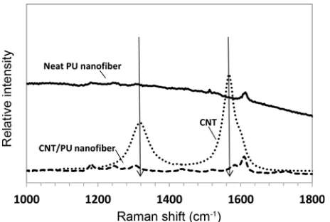
To confirm whether CNTs were properly incorporated in/ on the PU nanofibers, Raman spectral analysis was performed on the fabricated nanofibers (see Figure 5). The prominent CNT peaks at 1320 cm-1
and 1575 cm-1
correspond to the D-band (associated to defects) and G-D-band (in plane vibrations) of the CNTs, respectively [41,42]. Upon checking the Raman spectra of nanofibers, one can clearly see additional peaks for the CNT/PU nanofibers compared to the neat PU nanofibers. The new peaks are attributed to the presence of the CNTs in/on nanofibers, but slight peak shifts were observed, signifying interactions such as a newly-formed hydrogen bonds between PU and the CNTs [43].
Figure 3. (a) FE-SEM and (b) TEM images of the multiwalled carbon nanotubes used in the present study.
Mechanical Properties of Composite Laminates
Figure 6 shows the tensile properties of the present samples with Figure 6(A) showing the typical load-displacement curves and Figure 6(B) the average values of tensile strength and modulus. Table 2 summarizes the mechanical test results. From Figure 6(A), the tensile curves of the different samples have a similar characteristic trend. For all cases, the load of samples increases in a linear manner, and has a high slope. When the breakage occurred at the maximum point of load, they suddenly broke off. The composite laminates containing PU nanofibers with different CNT concentrations showed higher tensile strengths than the neat basalt/epoxy laminate (Figure 6(B)). It is worth noting that BPC-4, i.e., BFRP added with 3wt% CNT/PU with addition of surfactant resulted in the highest tensile strength from among all samples, with a further increase in tensile strain than the neat BFRP (Figure 6(A)). This is interesting in the sense that both
tensile strength and strain were increased. Bortz et al. [44] also noted the interesting increase in the stiffness, strength and strain of their composite carbon fiber reinforced composite (CFRP) laminates when they incorporated 1 wt% carbon nanofibers. Here, the addition of surfactant helps in the proper dispersion of CNTs in the nanofiber matrix. It is well known that effective load transfer from the polymer matrix to the nanoparticle filler is achieved when the latter is widely and evenly dispersed in the substrate. In Figure 6(B), it shows that the incorporation of nanofibers in the laminate has generally resulted to enhanced tensile strength (~4-13 % increase) and modulus (~6-20 %) compared to the neat BFRP (see Table 2). Increasing the CNT content from 1 wt% to 5 wt% in the PU nanofiber also showed increased tensile strength of the hybrid laminate. However, the BPC-4 (i.e., with surfactant) showed the highest increase, which could be attributed to the more dispersed state of the CNTs in the nanofiber due to surfactant addition. The better CNT dispersion lead to effective load transfer of PU matrix to the CNTs, due to high interfacial stress between the CNTs and PU [41,45, 46].
Figure 7 shows the flexural strength and modulus of the neat and hybrid composite laminates and the summary of results are given in Table 2. In the typical stress-strain curves (Figure 7(A)), the neat BFRP showed the highest flexural strain but the lowest flexural strength from among the tested samples. The incorporation of CNT/PU nanofibers in the BFRP showed increasing flexural strength with the increase in the amount of CNTs in the nanofibers, however, it also showed corresponding decrease in flexural strain. All samples showed linear increasing curves. The neat BFRP had a flexural strength of 378.70±16.77 MPa, and with the incorporation of CNT/PU nanofibers with 1 wt%, 3 wt%, and 5 wt% concentration, and 3 wt% CNT/PU with surfactant, the flexural strengths obtained were 403.27±20.43 MPa, 418.71 Figure 5. Raman spectra of the present CNTs, neat PU and CNT/
PU composite nanofibers.
±26.34 MPa, 421.76±22.23 MPa, and 444.09±23.95 MPa, respectively (see Figure 7(B) and Table 2). This translates to an increase of 6.5 %, 10.6 %, 11.4 %, and 17.3 % from that of the neat BFRP, respectively. Moreover, the hybrid composite
laminates showed increasing flexural modulus with the increase in CNT concentration in PU nanofibers, with BPC-4 (i.e., with surfactant) showing the highest increase.
Fracture Surface
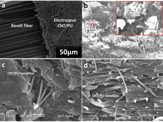
Many of the previous reports only focused on the incorporation of filler materials such as nanoparticles or nanofibers to provide load transfer from the epoxy matrix [47-49]. However, very few studies have reported on the multi-scale nanofiller reinforcements for epoxy matrix in FRP laminates. In this study, a multi-scale nanofiller reinforcement was provided to the BFRP with epoxy as its main polymer matrix. Figure 8(a) shows the difference in size scale between basalt fibers and electrospun CNT/PU nanofibers. The nanofiber, due to its ultrafine structure as nanofiller could provide very high Table 2. Average values of the tensile and flexural properties of the
present neat BFRP and hybrid composite laminates
Specimen Tensile test Flexural test
σtens (MPa) Etens (GPa) σflex (MPa) Eflex (GPa)
BFRP 414.27±7.66 17.112±0.208 378.70±16.77 15.87±1.36 BPC-1 432.37±15.03 20.528±1.179 403.27±20.43 15.91±0.76 BPC-2 435.74±5.50 20.194±0.253 418.71±26.34 17.94±1.12 BPC-3 459.19±17.75 18.270±0.406 421.76±22.23 18.79±0.66 BPC-4 467.33±18.02 19.347±0.622 444.09±23.95 19.20±2.43
Figure 7. (A) Typical flexural stress-strain curves and (B) average flexural strength and modulus of the neat BFRP and hybrid composite laminates.
surface area and more reactive sites for complete interaction with the epoxy matrix, thus can help in improving the properties of the composite [50,51]. The large surface area of nanofibers prohibits the epoxy chains from moving freely as in the case of neat epoxy matrix [52]. The further addition of much smaller carbon nanotubes inside the nanofibers could enhance more the mechanical properties of hybrid material. In this case, load transfer from PU to CNT is achieved especially when CNTs are uniformly dispersed in the PU matrix. Additionally, when PU nanofiber is added in the basalt fiber/epoxy matrix, the PU nanofibers absorbs some of the loads from the epoxy matrix, thus increasing more the mechanical properties of the hybrid composite laminate. In the present study, the same increasing trend results were seen for both the tensile and flexural strengths of the hybrid laminates containing CNT/PU nanofibers with different CNT concentrations. The results could be explained by investigating what is happening inside the matrix, thus we obtained SEM images of the cross-sections. Figures 8(b)-(d) show the cross-sectional images of the samples after mechanical tests. It can be seen that the neat BFRP (Figure 8(b)) has apparent delaminations and cracks between the basalt fiber and the epoxy matrix, and cracks in the epoxy matrix. Basalt fiber pull-outs were also observed indicating that some basalt fibers were not highly adhered to the epoxy matrix. Some void areas were also noticed indicating the non-uniform lamination of some parts leading to decreased mechanical properties. However, as nanofibers were incorporated (Figures 8(c) and 8(d)), a more dense and less-void lamination was observed. Though there were also some delaminations and crack that occurred especially at the matrix region, no apparent delamination was observed in the nanofibers zone. Similar observation was also reported by Liu et al. [53]. The nanofibers have several folds higher surface area than the basalt fiber thus, nanofibers provide high surface reactive area for the epoxy to adhere to. Furthermore, it could be that some CNTs were protruding from the nanofiber surface thus giving additional area and anchoring sites for the epoxy matrix (Figure 8(d)). Adding CNTs into the polymer matrix restricts the mobility of near interface molecules [54]. This resulted to increase mechanical strength of the hybrid composites compared to neat BFRP. When surfactant was used to dispersed the CNTs in the nanofibers, it gives more dispersability for CNT and be uniformly distributed in the PU nanofibers. The better distribution of CNTs in the nanofibers means better load transfer from PU nanofiber matrix to CNT. As observed in the Raman spectral analysis (Figure 5), interactions between CNTs and PU through possible hydrogen bonding provide effective load transfer from PU nanofiber to CNTs that enhances the mechanical properties of the CNT/PU composite compared to the neat PU alone. Carboxyl groups that are present on CNT surface can increase the local cross-linking density [54]. Moreover, there is an additional load transfer from the epoxy matrix to
the ultrafine, high-surface area CNT/PU nanofibers that are well-impregnated due to their smaller size [53]. The interaction between basalt fiber and epoxy resin is not clearly understood, however, a recent study by Kim [55] showed good interaction between basalt fibers and epoxy resin, wherein basalt incorporation limits the mobility of the epoxy polymer chains and improves the mechanical properties of the whole composite laminate.
Conclusion
The goal of this study was to develop and evaluate the mechanical properties of an epoxy-based laminate reinforced with different filer materials in various scale dimensions including basalt fibers, electrospun polyurethane (PU) nanofibers, and carbon nanotubes (CNTs). PU nanofibers containing different amounts of CNTs were interleaved between basalt fibers and laminated with epoxy as the matrix via VARTM. We investigated the effect of multi-scale reinforcements on the tensile and flexural properties of the hybrid composite laminates. Different characterization and mechanical property measurements were carried out on hybrid composites laminates. Our results indicate increased tensile and flexural properties when PU nanofibers with CNTs were incorporated in the hybrid composites compared to neat basalt fiber-epoxy (BFRP) composite only. Furthermore, increasing mechanical properties were observed when the CNT contents in the PU nanofibers were also increased. When surfactant was used to disperse CNTs in the PU nanofiber-reinforcements, the maximum increase of 13 % in tensile strength and 17.3 % in flexural strength compared to neat BFRP were obtained. The incorporation of PU nanofibers in the laminate produced more dense epoxy laminate and more adhered with high surface area nanofibers, leading to better mechanical properties of the hybrid composite laminate. The present study presents a facile way to further improve the mechanical properties of a basalt fiber-epoxy composite laminate with the use of nanotechnology such as electrospinning and nanoparticle incorporation.
Acknowledgement
This research was supported by a grant from the Basic Science Research Program through the National Research Foundation of Korea (NRF) funded by the Ministry of Science, ICT and Future Planning (2010-0022359).
References
1. E. Guades, T. Aravinthan, M. Islam, and A. Manalo, Compos. Struct., 94, 1932 (2012).
2. Q. Chen, L. Zhang, A. Rahman, Z. Zhou, X.-F. Wu, and H. Fong, Compos. Part A-Appl. S., 42, 2036 (2011).
Santos, Fiber. Polym., 13, 1292 (2012).
4. A. P. Mouritz and A. G. Gibson, Fire Properties of Polymer Composite Materials, in Springer, 2006.
5. K. Singha, Int. J. Text. Sci., 1, 19 (2012).
6. A. Mahmood, R. H. Gong, and I. Porat, Fiber. Polym., 14, , 591 (2013).
7. B. Wei, S. Song, and H. Cao, Mater. Des., 32, 4180 (2011). 8. I. D. G. Ary Subagia, L. D. Tijing, Y. Kim, C. S. Kim, F. P. Vista Iv, and H. K. Shon, Compos. Part B-Eng., In press 58, 611(2014).
9. K. Bilge, E. Ozden-Yenigun, E. Simsek, Y. Z. Menceloglu, and M. Papila, Compos. Sci. Technol., 72, 1639 (2012). 10. M. Shokrieh and M. Memar, Appl. Compos. Mater., 17,
121 (2010).
Nutt, Compos. Part A-Appl. S., 40, 1082 (2009).
15. E. Bekyarova, E. T. Thostenson, A. Yu, H. Kim, J. Gao, J. Tang, Langmuir, 23, 3970 (2007).
16. E. Bekyarova, E. T. Thostenson, A. Yu, M. E. Itkis, D. Fakhrutdinov, T. W. Chou, J. Phys. Chem. C, 111, 17865 (2007).
17. D. Dean, A. M. Obore, S. Richmond, and E. Nyairo, Compos. Sci. Technol., 66, 2135 (2006).
18. B. Fiedler, F. H. Gojny, M. H. G. Wichmann, M. C. M. Nolte, and K. Schulte, Compos. Sci. Technol., 66, 3115 (2006). 19. W. Chen, H. Shen, M. L. Auad, C. Huang, and S. Nutt,
Compos. Part A-Appl. S., 40, 1082 (2009).
20. S. Agarwal, A. Greiner, and J. H. Wendorff, Adv. Funct. Mater., 19, 2863 (2009).
21. A. Baji, Y.-W. Mai, S.-C. Wong, M. Abtahi, and P. Chen, Compos. Sci. Technol., 70, 703 (2010).
22. N. Bhardwaj and S. C. Kundu, Biotechnol. Adv., 28, 325 (2010).
23. K. Molnar, L. M. Vas, and T. Czigany, Compos. Part B-Eng., 43, 15 (2012).
24. L. D. Tijing, J.-S. Choi, S. Lee, S.-H. Kim, and H. K. Shon, J. Membr. Sci., 453, 435 (2014).
25. Z. M. Huang, Y. Z. Zhang, M. Kotaki, and S. Ramakrishna, Compos. Sci. Technol., 63, 2223 (2003).
26. Q. Chen, L. F. Zhang, A. Rahman, Z. P. Zhou, X. F. Wu, and H. Fong, Compos. Part A-Appl. S., 42, 2036 (2011). 27. A. D. Kelkar, R. Mohan, R. Bolick, and S. Shendokar, Mater.
Sci. Eng. B-Adv. Funct. Solid-State Mater., 168, 85 (2010). 28. J. Zhang, T. Lin, and X. G. Wang, Compos. Sci. Technol.,
70, 1660 (2010).
29. S. Sihn, R. Y. Kim, W. Huh, K. H. Lee, and A. K. Roy, Compos. Sci. Technol., 68, 673 (2008).
30. R. Palazzetti, A. Zucchelli, C. Gualandi, M. L. Focarete, L.
Donati, and G. Minak, Compos. Struct., 94, 571 (2012). 31. W. H. Yang, S. H. Yu, R. Sun, and R. X. Du, Ceram. Int., 37. A. D. Kelkar, R. Mohan, R. Bolick, and S. Shendokar,
Mater. Sci. Eng.: B, 168, 85 (2010).
38. ASTM-D638-10, “Standard Test Method for Tensile Properties of Plastics”, ASTM International: West Conshohocken, PA 19428-2959, United States, 2008. 39. ASTM-D790-10, “Standard Test Methods for Flexural
Properties of Unreinforced and Reinforced Plastics and Electrical Insulating Materials”, ASTM International: West Conshohocken, PA 19428-2959, United States, 1-11 (2010).
40. S. J. Han and D. D. L. Chung, Compos. Sci. Technol., 71, 1944 (2011).
41. W. Chen, X. M. Tao, and Y. Y. Liu, Compos. Sci. Technol., 66, 3029 (2006).
42. L. D. Tijing, W. Choi, Z. Jiang, A. Amarjargal, C.-H. Park, H. R. Pant, Curr. Appl. Phys., 13, 1247 (2013).
43. T. Ramanathan, H. Liu, and L. C. Brinson, J. Polym. Sci. Part B-Polym. Phys., 43, 2269 (2005).
44. D. R. Bortz, C. Merino, and I. Martin-Gullon, Compos. Part A-Appl. S., 42, 1584 (2011).
45. J. S. Jeong, J. S. Moon, S. Y. Jeon, J. H. Park, P. S. Alegaonkar, and J. B. Yoo, Thin Solid Films, 515, 5136 (2007).
46. H. C. Kuan, C. C. M. Ma, W. P. Chang, S. M. Yuen, H. H. Wu, and T. M. Lee, Compos. Sci. Technol., 65, 1703 (2005). 47. K. L. White and H. J. Sue, Polymer, 53, 37 (2012). 48. J. H. Lee, K. Y. Rhee, and S. J. Park, Mater. Sci. Eng.
A-Struct. Mater. Prop. Microstruct. Process., 527, 6838 (2010). 49. S. Sihn, R. Y. Kim, W. Huh, K.-H. Lee, and A. K. Roy,
Compos. Sci. Technol., 68, 673 (2008).
50. L. D. Tijing, M. T. G. Ruelo, A. Amarjargal, H. R. Pant, C. H. Park, and C. S. Kim, Mater. Chem. Phys., 134, 557 (2012). 51. L. D. Tijing, C. H. Park, W. L. Choi, M. T. G. Ruelo, A. Amarjargal, H. R. Pant, Compos. Part B-Eng., 44, 613 (2012).
52. M. Alexandre and P. Dubois, Mater. Sci. Eng. R-Reports, 28, 1 (2000).
53. L. Liu, Z. M. Huang, C. L. He, and X. J. Han, Mater. Sci. Eng. A-Struct. Mater. Prop. Microstruct. Process., 435, 309 (2006). 54. W. Chen, H. Lu, and S. R. Nutt, Compos. Sci. Technol., 68,
2535 (2008).