DETECTION AND TRACKING OF MOVING OBJECTS WITH REAL-TIME ONBOARD
VISION SYSTEM
D.Y. Erokhin a, A.B. Feldman a, S.E. Korepanov a
a Dept. of Automation and Information Technologies in Control, Ryazan State Radio Engineering University,
390005, Gagarina Str. 59/1 Ryazan, Russia – [email protected]
Commission II, WG II/5
KEY WORDS: Detection, Tracking, Background estimation, Motion object, Geometrical transform estimation
ABSTRACT:
Detection of moving objects in video sequence received from moving video sensor is a one of the most important problem in computer vision. The main purpose of this work is developing set of algorithms, which can detect and track moving objects in real time computer vision system. This set includes three main parts: the algorithm for estimation and compensation of geometric transformations of images, an algorithm for detection of moving objects, an algorithm to tracking of the detected objects and prediction their position. The results can be claimed to create onboard vision systems of aircraft, including those relating to small and unmanned aircraft.
1. INTRODUCTION
In this paper we present our solution to moving object detection and multiple object tracking tasks. This set of algorithm is developed to work on onboard video system. Because of our set of algorithm is developed for onboard vision system it can works in some conditions: low contrast of objects of interest in relation to the background, inhomogeneity of the optical medium and various atmospheric phenomena, crossing trajectories of tracking objects, occlusion of objects with elements of the background, quickly changes of the observed scene.
Image analysis should be performed in real time, but at the same time the resources of onboard hardware are, very limited. Because of the wide variety of possible objects, backgrounds and viewing conditions, image analysis algorithms designed for onboard vision systems should have the necessary versatility and operate with a minimum of a prior information.
Object detection task is one of the most important problem in many technical vision applications. Nowadays existing a lot of different solutions for object detections. But we don’t have a solution which would be work properly in different situations. In work (Lu, 2006) was introduced the algorithm of automatic detection of objects using histograms of oriented gradients (Dalal, 2005).
Also exist some object detection algorithms based on colour information (Lefevre, 2003), (Gorry, 2007), but usually we can’t use colour image in onboard technical vision systems because of limited computing resources.
There are approaches to detection objects using machine learning based algorithms (Papageorgiou, 1998). To use such approaches, it is necessary to create a training samples, which is not always easy to do because of the wide variety of objects of interest and observation conditions.
In some work (Stauffer, 1999), (Bouwmans, 2008) mixture of Gaussian is used for detection, but usually this approach is applied to video received from stationary video sensor.
Despite the wide variety of known approaches to detect objects in video sequence, one can note that they either don’t always have acceptable computational complexity, or are too demanding for the presence of a priori information about objects of interest, or don’t demonstrate the proper quality in conditions of rapid shift and rotations of the video sensor.
In this paper we propose a set of algorithms designed to solve the task of selection and tracking of moving objects. Proposed algorithms don’t require prior information about object of interest and have acceptable computational complexity.
The set of algorithm composed from three main part: algorithm for estimation and compensation of geometric transformations of images, algorithm for detecting of moving objects and algorithm for object tracking and predicting their position in case of occlusion.
2. ALGORITHM FOR ESTIMATION AND COMPENSATION OF GEOMETRIC
TRANSFORMATIONS
The most common practice is the installation of a video sensor on a gyrostabilized platform placed on board an aircraft. Algorithm should take into account the motion of the carrier of the system. That’s why we have mismatch between neighbouring frames.
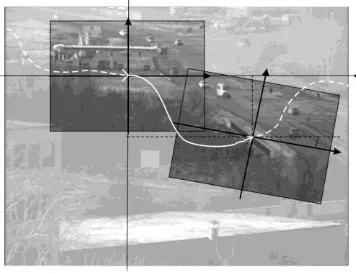
Algorithm for estimation and compensation of geometric transform is depend on mathematical model of transform. In our case the distance between video sensor and observed scene is much bigger then scene depth and bigger than shift between consecutive frames. In this conditions we can use the Euclidian model of transformation, which assumes rotation and shift. Euclidian model of transformation is represented in figure 1. The International Archives of the Photogrammetry, Remote Sensing and Spatial Information Sciences, Volume XLII-2/W4, 2017
For shift estimation in this work we use phase correlation (Reddy, 1996). But the modification of this algorithm can be used for rotation estimation. For rotation estimation we should transform magnitude of spectrum from cartesian to polar coordinate system. And after that applied cross correlation to this images, the axial shift will be determinate the rotation.
The estimation end compensation of geometrical transform are performed in two steps: evaluation and compensation of rotation, evaluation and compensation of shift. The advantages of this approach are subpixel precision, acceptable computational complexity.
Figure 1. Euclidian transformation of the image
This algorithm based on phase correlation allows us to estimate the vector of parameters of geometrical transformations with a sufficiently high accuracy, which allow us to obtain background estimation to solve the task of detection of moving objects.
For additional reduce computational costs we estimate geometrical transform in window, for example, we use window with size a 256 by 256 pixels. It should be noted that further reduction the size of the window is not advisable, since it leads to a significant decrease in the accuracy of the estimation of the transformation parameters.
3. ALGORITHM FOR DETECTION OF MOVING OBJECTS
Now we introduce model of observed image. For simplicity, we consider that we have only one object:
)
where i, j = pixels coordinates n = frame number l(i, j, n) = observed image g(i, j, n) = background image h(i, j, n) = object image
r(i, j, n) = binary image, values of which correspond to the object
) , , (i jn
= normal Gaussian noise with standard deviation σ(i, j, n)
The image of the object is unknown a priori. In this case, we will assume that the brightness of the points of the object have a uniform distribution. Thus, it is necessary to estimate r(i, j, n) from the observed image. We denote the estimate r(i, j, n) by the symbol rˆ(i,j,n).
After establishing the geometric correspondence between frames, we perform an estimation of the background image.
Suppose that to the frame n we have relevant estimation of the background gˆ(i,j,n). In accordance with the Neumann-Pearson criterion, the following conditions must be satisfied:
p = probability of true positive decision
Since the decision on the belonging of a point to an object or background is taken independently for each point, it is advisable to omit further indices (i, j, n).
Let the brightness of the object be uniformly distributed in the
Then the optimal estimation of the object's binary mask can be found from expression:
object can be represented in the next form:
acceptable level of false alarm)
2 memory of an exponential filter.
Usually β lies in the range from 0.85 to 0.97. At points where geometric transformations of the observed scene, the greatest errors in estimating the brightness of the background points will be at the boundaries of the contrast objects. To reduce the effect of errors of this kind, we will take into account the values of the brightness difference:
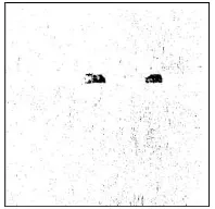
binary image. Errors of another kind are due to the fact that it is not possible to detect a part of the points belonging to the objects of interest. In this case, one object can be represented by two or more segments in one image. This effect leads to the identification of individual segments as different objects. In order to improve the results of object detection, a binary image is processed first by a median filter, and then simplify morphological operations are applied to it (Gonzalez, 2008). The operation of a morphological closing is used to combine closely spaced segments, and also allows filling gaps. The operation of morphological spreading, on the contrary, allows to get rid of the small segments that remained after the median filtration. The result is shown in figure 2, 3.After binarization, it is necessary to obtain a list of segments of the current frame, using the markup and parameterization algorithm presented in (Alpatov, 2011a). As a result, we get a list of segments, which should be compared with the traced objects. The filtering which allows us to reject segments by size is performed simultaneously with marking.
The limitation of this approach is that for solving the problem of detecting objects it is necessary to estimate of the brightness of the background points. Thus, the zone in which objects can be allocated is limited and depends on the speed of the geometric transformations of the observed scene. Experiments show that for obtain a reliable estimation of background it is necessary to process about 25-30 frames.
Figure 2. Result of binarization
Figure 3. Filtered binary image
4. OBJECTS TRACKING ALGORITHM
To track moving objects we must establish a correspondence between the list of tracked objects and the list of segments detected in the current frame. To solving this task in this work we use trajectory graph (Alpatov, 2011b), (Alpatov, 2015). To construct a trajectory graph, we must select a quantitative measure of the correspondence between the tracked objects and the detected segments. As such a measure, we use the Euclidean distance between the center of the detected segment and the predicted center of the object, calculated using the Kalman filter. As a result, we get a full bipartite graph, where the vertices of the first set correspond to segments, the vertices of the second set correspond to the objects, and the edges weights are the distance between the corresponding pair of vertices.
The procedure for constructing a trajectory graph consists of several basic steps:
1. Find in the graph connected components.
2. In all non-elemental components, remove the edge with the maximum weight
3. If there are non-elementary components left in the graph, go to step 1, otherwise the trajectory graph is constructed.
As result we obtain a trajectory graph which example is shown on the figure 4.
Figure 4. Trace graph
A trajectory graph can be formed by five types of elementary components:
1. In the connectivity component there is one vertex that corresponds to the object. In this case, this object is not detected on the current frame. Fig. 4, component G1.
2. In the connectivity component there is one vertex that corresponds to the segment. In this case, a new object is detected on the current frame. Fig. 4, component G2.
3. In the component there are two vertices, the first corresponds to the object, and the second corresponds to the segment. In this case, a traceable object is detected on the current frame. Fig. 4, components G4, G6.
4. There are three vertices in the component, two of which correspond to the objects, and one corresponds to the segment. In this case, tracks were merged. Fig. 4, component G5. 5. There are three vertices in a component, two of which correspond to segments, and one corresponds to an object. In this case, there was a separation of tracks. Fig. 4, component G3.
If the object was not detected in the current frame its position is predicted using the Kalman filter. If the object disappears for a long time it is removed from the list of traces.
5. EXPERIMENTAL RESEARCH
To evaluate the accuracy of the algorithm for estimating and compensating geometric transformations of images two video sequences were synthesized. Each frame has a random shift in -5 and -5 pixels diapason and rotation with ± -5 degree diapason. Table 1 shows how the window size in which the transformation parameters are evaluated is affected by the accuracy of the algorithm. In the experiment, the RMS errors of shift estimation along the OX – x and OY – y axes were
calculated, as well as the errors in the rotation estimation –.
Window size, pixel
Value, pixel
Video
№1 №2
128 x 128
x
0.12 0.11
y
0.13 0.1
0.07 0.06
256 x 256
x
0.09 0.094
y
0.1 0.95
0.06 0.05
400 x 400
x
0.08 0.08
y
0.84 0.07
0.06 0.06
Table 1. Effect of window size on the accuracy of determining the parameters of geometric transformations
As can be seen from Table 1, windows with a size of 256 by 256 are sufficient to determine the vector of Euclidean transformations with good accuracy. The further increase in the size of the window has almost no effect on accuracy, but it avoids situations when the video sensor actually moves, but the image remains unchanged, which may occur in the case of a regular scene structure.
To assess the accuracy of the detection of mobile objects, an operational characteristic has been experimentally constructed. For this, three outdoor video with shifts and rotations. For each 25th frame of these videos, binary masks corresponding to the observed objects were manually marked. The average signal-to-noise ratio on test video was calculated by the formula:
K
k k
k k
h g
K SNR
1
1
(10)
where hk = average brightness of k object points
k
g = average background brightness in the vicinity of the k object
k
= RMS of noise computed for the frame in which the k object was observed
The experimental operational characteristic, obtained with an average signal-to-noise ratio 3, is shown in Figure 5.
Figure 5. Receiver operating characteristic curve
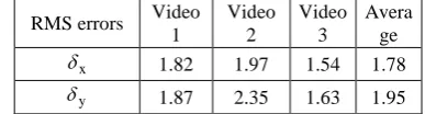
The accuracy of measurement the coordinates of objects was estimated with the use of 3 outdoor video with duration of 100 frames each. The videos are obtained in the visible range and contain the urban landscape and elements of the rugged terrain. On the first and second videos there are interframe shifts and rotation, on the third video-camera the camera is fixed. For each frame, the true positions of the objects in the image were entered manually. The average size of objects is 30x20 pixels. In the course of the experiment, the values of the RMS errors in estimating the coordinates of the object along the axis OX – x
and along the axis OY – y were calculated. The results of the
experiment are shown in Table. 2. One can notice that the results on the video with a static background only slightly better than results on the video received by the moving camera. This indicates a good work of the algorithm for compensating geometric transformations.
RMS errors Video 1
Video 2
Video 3
Avera ge
x
1.82 1.97 1.54 1.78
y
1.87 2.35 1.63 1.95
Table 2. RMS errors in determining the coordinates of objects
To test the workability of the algorithm for tracking mobile objects, a video sequence was used from the site http://www.yale.edu/perception/Brian/demos/MOT-Basics.html. The International Archives of the Photogrammetry, Remote Sensing and Spatial Information Sciences, Volume XLII-2/W4, 2017
In this video sequence, there are many objects of interest that move along intersecting trajectories. Also, tests were conducted on real videos. The tests showed that the tracking algorithm based on the trajectory graph successfully handles cases of obscuration of objects of interest.
6. CONCLUSION
The presented complex of algorithms was implemented in C ++. Processing of frames of 640 by 480 pixels using a computer based on Intel Core 2 Duo T7100 is carried out in real time at a rate of 25 frames per second. The obtained results of the experiments testify to the possible application of this set of algorithms in the onboard system of technical vision.
ACKNOWLEDGEMENTS
The work has been supported by the grant for the Leading Scientific Schools of the Russian Federation (NSh-7116.2016.8).
REFERENCES
Alpatov B. A., Babayan P.V., Balashov O.E., Stepashkin A.I. (2011a). Image processing and control in systems of automatic attending of objects– Ryazan. –235 с.
Alpatov, B., & Babayan, P. (2011b, October). Multiple object tracking based on the partition of the bipartite graph. In SPIE Security+ Defence (pp. 81860B-81860B). International Society for Optics and Photonics.
Alpatov, B., & Babayan, P. (2010, October). Extraction of the objects observed on a non-uniform background during sensor motion. In Security+ Defence (pp. 78350N-78350N). International Society for Optics and Photonics.
Alpatov, B., Babayan, P., & Strotov, V. (2015, October). The implementation of multiple objects tracking algorithm based on partition of bipartite graph in FPGA-based onboard vision systems. In SPIE Remote Sensing (pp. 964602-964602). International Society for Optics and Photonics.
Bouwmans, T., El Baf, F., & Vachon, B. (2008). Background modeling using mixture of gaussians for foreground detection-a survey. Recent Patents on Computer Science, 1(3), 219-237.
Dalal, N., & Triggs, B. (2005, June). Histograms of oriented gradients for human detection. In Computer Vision and Pattern Recognition, 2005. CVPR 2005. IEEE Computer Society Conference on (Vol. 1, pp. 886-893). IEEE.
Gonzalez, R., & Woods, R. Digital image processing. 2008.
Gorry, B., Chen, Z., Hammond, K., Wallace, A., & Michaelson, G. (2007, November). Using mean-shift tracking algorithms for real-time tracking of moving images on an autonomous vehicle testbed platform. In Proceedings of World Academy of Science, Engineering and Technology (Vol. 25, No. 11, pp. 1307-6884).
Lefevre, S., Bouton, E., Brouard, T., & Vincent, N. (2003, September). A new way to use hidden Markov models for object tracking in video sequences. In Image Processing, 2003. ICIP 2003. Proceedings. 2003 International Conference on (Vol. 3, pp. III-117). IEEE.
Lu, W. L., & Little, J. J. (2006, June). Simultaneous tracking and action recognition using the pca-hog descriptor. In Computer and Robot Vision, 2006. The 3rd Canadian Conference on (pp. 6-6). IEEE.
Papageorgiou, C. P., Oren, M., & Poggio, T. (1998, January). A general framework for object detection. In Computer vision, 1998. sixth international conference on (pp. 555-562). IEEE.
Reddy, B. S., & Chatterji, B. N. (1996). An FFT-based technique for translation, rotation, and scale-invariant image registration. IEEE transactions on image processing, 5(8), 1266-1271.
Stauffer, C., & Grimson, W. E. L. (1999). Adaptive background mixture models for real-time tracking. In Computer Vision and Pattern Recognition, 1999. IEEE Computer Society Conference on. (Vol. 2, pp. 246-252). IEEE.