BUNDLE BLOCK ADJUSTMENT WITH SELF-CALIBRATION OF LONG ORBIT
CBERS-02B IMAGERY
Yongjun Zhang, Maoteng Zheng
School of Remote Sensing and Information Engineering, Wuhan University, Wuhan 430049, P. R. China
[email protected], [email protected]Commission I, WG I/4
KEY WORDS: Linear array imagery, Bundle block adjustment, Interior orientation parameters, Self-calibration, Sensor model
ABSTRACT:
CBERS-02B was the first high resolution earth observation satellite in China, which adopted linear array push-broom sensor. The nadir ground resolution of the on board HR camera was 2.36 m. However, the accuracies of the on-board GPS receiver and star tracker were very limited due to the technical restrictions. The accuracy of direct geo-referencing by the on-board measurements of position and attitude parameters was about 1 kilometre, which restrained the wide applications of the CBERS-02B imagery in the surveying and mapping field. It is necessary to perform the bundle block adjustment to improve the accuracy of geo-referencing. A proper sensor model has to be adopted during the bundle block adjustment using strict physical sensor model with long orbit data, in order to solve the problem of too many unknown exterior orientation parameters (EOPs). Several sensor models have been discussed, such as quadratic polynomial model, systematic error compensation model, orientation image model, and piecewise polynomial model. The combination of the systematic error compensation model and the orientation image model will be used to deal with the CBERS-02B imagery in this paper. Furthermore, three TDI-CCD linear arrays were fixed on the focal plane of the HR camera. The middle CCD array was shifted against the left and the right one. The level 1A image used in this paper was mosaicked by the three sub-images collected by the left, the middle and the right CCD, respectively. But there were some displacements among the three sub-images in the mosaicked image and the three CCD arrays may not be rigorously parallel. The angular parameter a and the translation parameters x, y of each CCD refer to the theoretical position on the focal plane is used to model the interior distortions, so there are totally 9 interior distortion parameters, although some of them are not significant. The laboratory calibrated parameters of the image sensor are usually different from the true values after launch. So a self-calibration strategy should be applied in the bundle block adjustment. Plenty of automatically matched GCPs with precision of 10 meters in plane and 20 meters in height are used to perform the bundle adjustment. Both the systematic error compensation model and the orientation image model with the interior self-calibration parameters are used in the bundle block adjustment to eliminate the systematic errors caused by the camera internal distortions and to improve the precision of geo-referencing. A best combination of interior orientation parameters (IOPs) is drawn from the adjustment results with different combinations of these IOPs. Besides, there may be some gross errors in the automatically matched GCPs. The gross errors among GCPs may lead to unusual variation of the exterior orientation elements by time. Methods of enlarging the intervals of orientation image and increasing the weights of the position and attitude observations are applied in the combined bundle block adjustment to remove the influence of gross errors of GCPs. The preliminary experimental results show that for longer than 1000 km orbit data, the average accuracy of self-calibrated bundle block adjustment combined with GPS and star tracker observations is 2 pixels better than that without self-calibration. The planar position accuracies in X and Y of check points are 8 m and 7 m respectively.
1. INTRODUCTION
In recent years, the resolution of satellite imagery has been largely improved to 1 meter or even better. It’s reported that the resolutions of IKONOS and QuickBird are 1 meter and 0.61 meter respectively. Up to now, GeoEye-1 0.41 meter ground resolution is the highest resolution commercial satellite in the world. All these satellites adopted linear push-broom imaging mode to acquire high quality linear-array imagery while integrated with high precision GPS receivers and star trackers to measure its instantaneous position and attitude data at the imaging time. These auxiliary data are transferred to ground station and used to perform direct geo-referencing. The accuracy of direct geo-referencing can achieve 3 meters using auxiliary data of GeoEye-1 (Fraser, 2009).
CBERS-02B is the first high resolution earth observation satellite in China, the on board HR camera applied TDI-CCD (time delay and integrate CCD) scanning mode which is widely used in earth observation satellites such as IKONOS (YUE,
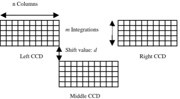
2009). The TDI-CCD device has high SNR (signal and noise ratio) and sensitivity, but the internal construction and optical geometry is more complicated than conventional CCD unit, which leads to the difficulty of data processing. A TDI-CCD device is actually a matrix array consists of m lines of CCD arrays, where m means the number of CCD lines. However, in the TDI scanning mode, the concept of frames did not exist because the CCD lines was designed to imaging the same corresponding line on the ground at different time. The m CCD units at the same column will image the same ground object in turn, and the output signal will be amplified by accumulating all these signals which are captured by the m CCDs. The geometry of TDI-CCD alignment is shown in figure 1. It was composed of three TDI-CCD devices which were installed on the left, middle and right of the focal plane, respectively. The middle TDI-CCD was shifted at a distance d against the other two. International Archives of the Photogrammetry, Remote Sensing and Spatial Information Sciences, Volume XXXIX-B1, 2012
Figure 1. The designed distribution of TDI-CCD arrays on the focal plane of CBERS-02B HR Camera
The accuracy of direct geo-referencing with auxiliary data of CBERS-02B can not meet the requirements of mapping applications, thus a few ground control points were needed to perform the bundle block adjustment with linear array imagery to improve the accuracy of geo-positioning. Sensor models for bundle block adjustment with linear array satellite imagery can be categorized into two classes, generic model and strict physical model. Generic model is always referred to Rational Function Model (RFM) or Rational Polynomial Coefficients (RPC) which is also defined as Rapid Positioning Capability (Zhen, 2009). It’s a mathematical function that is adopted to model the relationship between image coordinates and object coordinates. Strict physical model is to use EOPs and IOPs to represent the sensor’s instantaneous position, attitude and camera geometry at the time of scanning. Ground object coordinates can be calculated by these EOPs and IOPs according to the collinearity condition. Bundle block adjustment is usually used to recover all these parameters. Since we are dealing with linear array imagery, a proper trajectory model has to be adopted to represent the EOPs’ variations by time and decrease the number of unknown parameters. Several sensor models, such as quadratic polynomial model (Taejung, 2006), systematic error compensation model, orientation image model (Ohlhof, 1995; Zhao, 2006) and piecewise polynomial model, are widely used. As to 02B imagery, Yue Qing-xing and J. Marcato adopted quadratic polynomial model to perform the bundle block adjustment (YUE, 2009; Marcato, 2010).
Since the internal construction of the TDI-CCD devices in CBERS-02B HR camera is complicated, the IOPs has to be introduced during bundle block adjustment to eliminate the misalignment error of TDI-CCD devices, and to improve the precision of geo-referencing. Yue Qing-xing had introduced three translation parameters along track refer to the left, middle and right TDI-CCD, respectively (YUE, 2009). However, this scheme can only eliminate the TDI-CCD translation errors along track, systematic errors across track still exist. There may also be a rotation angle between the real position and the designed position of the TDI-CCD devices. Moreover, the CCD size error and CCD bending error also exist. Since these two kinds of errors have little influence on the result of bundle block adjustment, and the precision of the automatically matched control points are too low to identify these errors, they will be neglected in this paper.
The systematic error compensation model is combined with orientation image model to perform bundle block adjustment, the translation and rotation parameters are introduced to eliminate the TDI-CCD misalignment error. 10 parameters including f referred to the focal length, (a1, △x1, △y1), (a2, △ x2, △y2), and (a3, △x3, △y3) referred to the corrections of the left, middle and right CCD respectively were introduced into the bundle block adjustment with long orbit data, although
some of them are redundant. A proper combination of these IOPs will be drawn according to these experiments.
2. METHODOLOGY
2.1 Sensor model
As the EOPs of each scanning line are varying by time, and generally, the number of scan lines is very large, thus it’s unreasonable to solve all of the EOPs directly. A proper trajectory model is needed to represent the EOPs’ variation by time, and to decrease the number of unknown parameters. All the EOPs can be calculated by these model parameters which will be solved in the bundle block adjustment. Qaudratic polynomial model, systematic error compensation model, piece-wise polynomial model and orientation image model are mostly adopted models. In this paper, systematic error compensation model combined with orientation image model will be applied in the bundle block adjustment.
2.1.1 Systematic error compensation model
The systematic errors of the position and attitude data can be described by quadratic polynomials about time, the real position and attitude of satellite is equal to the position and attitude observations plus the corresponding systematic errors which are calculated by quadratic polynomial parameters and the corresponding imaging time:
2.1.2 Orientation image model
EOPs of orientation images refer to certain time were treated as unknowns, EOPs of each scaning lines at other time can be interpolated with the EOPs of adjacent orientation images which will be solved in the bundle block adjustment:
2
Where
P t
( )
j ,P t
( )
i are EOPs at timet
j andt
ik
t
is corresponding time of orientation image k2.2 Self-calibration model of interior parameters 2.2.1 Imaging geometry
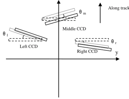
In this paper, a rotation angle and two translation parameters refer to left, middle and right TDI-CCD respectively are introduced in the bundle block adjustment.
Figure 2 CCD rotation and translation on the focal plane
Coordinates of image points on left, middle and right TDI-CCD can be calculated by following equations:
(
) sin
middle and right TDI-CCDl
2.2.2 Error equation:
2.2.2.1 Error equation of the systematic error compensation model
Where
x
is the unknowns’ vector of systematic compensation parametersiop
x
is the unknowns’ vector of IOPsl
is the discrepancy vector of image point observationiop
l
is the discrepancy vector of IOPs virtual observationA, C are design matrices
P
,P
iop are the weights of image point observationand IOPs virtual observations
2.2.2.2 Error equation of the orientation image model:
Where
x
gps is the unknown vector of translation parametersatt
x
is the unknown vector of rotation parametersiop
x
is the unknown vector of IOPs virtual observationsl
is the discrepancy vector of image point observationsgps
l
is the discrepancy vector of GPS observationsatt
l
is the discrepancy vector of star tracker observationsiop
l
is the discrepancy vector of IOPs virtual observationsP
,P
gps,P
att,P
iop are the weights of image point observations, GPS observations, star tracker observations and IOPs virtual observations3. EXPERIMENTS AND ANALYSIS In this paper, systematic error compensation model combined with orientation image model were adopted in the bundle block adjustment with IOPs introduced in. The systematic error compensation model is firstly used to eliminate the big systematic errors of the entire strip, and the orientation image model is then adopted to eliminate the remained systematic errors. A best IOPs combination scheme was drawn after many times of tests with different combinations of these IOPs. Since the position, attitude observations and IOPs virtual observations were introduced into the bundle block adjustment, only the proper weight matrix were fixed, the best adjustment result can be achieved. The weights of all observations were fixed according to their a priori precision. The weight of image point is set as unit weight, the weights of other group of observations are the squared ratio of their precision and image point precision.
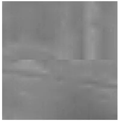
Real dataset collected by CBERS-02B HR linear scanner were used for experiments in this paper. The main technical parameters of this sensor are listed in Table 1. This camera adopted three TDI-CCD devices to acquire linear imagery as mentioned before. The output image is mosaicked by three images which were acquired by the left, middle and right TDI-CCD devices respectively, but there may still have seams in the mosaicked image as shown in Figure 3, and some CCD lines on sub-image is missing as shown in Figure 4.
A large number of control points were matched from topographic map with 1/10000 scale by automatic matching program, so there were some gross errors among these control points, thus the control point gross error elimination procedure is inevitable during the bundle block adjustment.
Sensorparameters Value
Focal length (mm) 3300 Pixel size (mm) 0.01 Width (pixel) 12000 Swath (km) 28.9 GSD (m) 2.36 Altitude (km) 780
Table 1. Sensor parameters of CBERS-02B HR camera
Figure 3. Mosaic error between the left and middle CCD image
Figure 4. Missing of scanner lines in the right CCD image
3.1 Bundle block adjustment with the left, middle, right sub-images and the whole image mosaicked by these three sub-images
The systematic error compensation model is firstly adopted to refine the EOPs, and then the orientation image model is applied to eliminate the remained systematic errors.
As illustrated in Table 2 and Figure 5, image point residues of bundle block adjustment with the left, middle or right sub-images is 2 to 3 pixels less than that of bundle block adjustment with the whole image, which means that the whole image mosaicked by the three sub-images still have misalignment error, and the calibration of interior parameters is necessary to eliminate the misalignment error caused by rotation and translation of TDI-CCD devices between the real and designed positions.
Data source
RMS of Image points
(pixel)
Maximum image point residues (pixel)
x y x y
Middle sub-image 2.1 2.5 -11.5 -12.0
Left sub-image 2.3 2.8 -14.3 15.5
Right sub-image 2.3 2.9 -15.6 13.9
Whole image 5.0 4.2 31.6 32.7
Table 2 Image point residues of bundle block adjustment with sub-images acquired by the left, middle, right sub-images and
the whole image mosaicked by the three sub-images
0.00 0.05 0.10 0.15 0.20 0.25 0.30 0.35
rms_x rms_y max_x max_y
Left CCD Middle CCD Right CCD All CCD
Unit: mm
Figure 5. Image point residues of bundle block adjustment with image points from sub-images acquired by the left, middle, right TDI-CCD units and the whole image mosaic by the three
sub-images
3.2 Bundle block adjustment with different combinations of IOPs
Ten IOPs at most are introduced in the adjustment, f is referred to the focal length, x0, y0, a0 are the two translation parameters and one rotation parameter referred to the left TDI-CCD; x1, y1, a1 are those of the middle TDI-CCD; x2, y2, a2 are those of the right TDI-CCD. Statistical results of image point residues and check point planar precision after bundle block adjustment with different combinations of IOPs are shown in Table 3.
As demonstrated in Table 3 and Figure 6, image point residues and check point planar precision after bundle block adjustment with 7 IOPs (scheme 3 in Table 3) were improved by 4 times at most compared with that with no IOPs (scheme 11 in Table 3). The adjustment did not converge if the translation and rotation parameters referred to middle TDI-CCD were set as unknowns. As can be seen from scheme 5, 6, 7, 8, if the rotation parameters were introduced in, image points residues in x direction (along track) were improved by 1.5 pixels, although the precision in the y direction (across track) did not change much. The planar precisions of check points were improved by one time in Y direction while no obvious improvement in X direction. A rotation angle among these three CCD lines may be exists according to the experiments. The focal length hasn’t any influence on the results whether it is set as unknowns or not because it is correlated with the height unknowns of EOPs and can be effectively compensated by the EOPs.
RMS of image points (pixel)
Max of image points
(pixel)
RMS of check points (m) Scheme
ID
Parameters combinations
x y x y X Y
1 f,x0,y0,a0,x1,y1,a1,x2,
y2,a2 -- -- -- -- -- -- 2 x0,y0,a0,x1,y1,a1,
x2,y2,a2 -- -- -- -- -- -- 3 f,x0,y0,a0 ,x2,y2,a2 1.2 2.0 -4.5 -6.6 5.5 6.1 4 x0,y0,a0 ,x2,y2,a2 1.2 1.8 -4.5 -5.9 4.9 6.1 5 f,x0,a0,x2,a2 1.4 2.1 5.6 -7.0 5.8 7.3 6 x0,a0,x2,a2 1.4 2.1 -5.4 -7.0 5.9 7.0 7 f,x0,y0,x2,y2 2.9 2.0 -9.8 -6.8 7.0 15.8 8 x0,y0,x2,y2 3.0 1.8 -9.7 -5.8 6.5 15.8 9 f,x0,x2 3.0 2.1 -9.9 -7.0 6.9 15.8 10 x0,x2 2.9 2.1 -9.9 -7.1 6.9 15.8 11 No parameter 5.0 4.2 31.6 32.7 8.9 24.1
Table 3. Image point residues and check point planar precision with different schemes of IOPs combination
(a) Image point residues with scheme 11 in Table 3
(b) Image points residues with scheme 3 in Table 3
Figure 6. Distribution of image point residues with different schemes
4. CONCLUSION
Different combinations of IOPs in the bundle block adjustment with CBERS-02B real data were tested in this paper, a best scheme was drawn according to these test results, and it can be concluded that:
1. The precision of bundle block adjustment with IOPs was improved by 2 to 3 pixels when compared to that without IOPs, which indicates that it is reasonable to perform bundle block adjustment with self-calibration. 2. The best result can be obtained when only the translation and rotation parameters of the left and right CCD was introduced, which also indicates that the 10 IOPs are correlated to each other. Solving all these 10 parameters simultaneously will lead to irreversible normal equation matrix. If the translation and rotation parameters of the middle CCD were set as known, the other parameters can be stably solved in the bundle block adjustment.
The IOPs can be obtained after the bundle block adjustment. However, the rectified orthoimage may have seam lines if the rotation angle parameters of IOPs are significant. So these rotation parameters should be controlled to insure that they will not get large values after bundle block adjustment.
ACKNOWLEDGEMENT
This work was supported by National Natural Science Foundation of China with project No. 41071233, National Hi-Tech Research and Development Program with project No. 2012AA12A301, and National Key Technology Research and Development Program with project No. 2011BAB01B05.
REFERENCES
Fraser C. S., Ravanbakhsh M., 2009. Georeferencing from GeoEye-1 imagery: early indications of metric performance.
Proceedings of the ISPRS 2009 Workshop, 'High-Resolution Earth Imaging for Geospatial Information,' Hannover, Germany, June 2-5.
Yue Qingxing, Zhou Qiang, Zhang Chunling, You Shucheng, Jia Yonghong, Qiu Zhenge, 2009. The adjustment of CBERS - 02B pan image, Remote Sensing for Land & Resources, Vol. 3, No. 1, pp. 61-63.
Zhen Xiong, 2009. Technical development for automatic aerial triangulation of high resolution satellite imagery. Fredericton. N. B. : Ph. D. Dissertation, Department of Geodesy and Geomatics Engineering University of New Brunswick, Canada.
Taejung Kim, Ian Dowman, 2006. Comparison of two physical sensor models for satellite images: position–rotation model and orbit–attitude model. The Photogrammetric Record 21(114): 110–123 (June 2006).
Ohlhof T., 1995. Block triangulation using three-line images. Proceedings of Photogrammetric Week 1995(Wichmann, Verlag, editor), Stuttgart, pp, 197-206.
Zhao Shuangming, Li Deren, 2006. Experimentation of adjustment math model for ADS40 sensor. Acta Geodaetica et Cartographica Sinica, Vol.35, No 4, Nov, 2006, pp. 342-346.
Marcato Jr, J., Tommaselli, A. M. G., Medeiros, N. G., Oliveira, R. A., 2010. Bundle block adjustment of cbers 2b hrc images using control lines In: Canadian Geomatics Conference 2010 and the International Symposium of Photogrammetry and Remote Sensing Commission I, Calgary.
Zhang Yongjun, Zheng Maoteng, Ke Tao, 2011. Triangulation of spaceborne three-line array imagery with different sensor models. In : ASPRS 2011 Annual Conference, Milwaukee, Wisconsin, 2011.