SYSTEMATIC BUNDLE ADJUSTMENT OF HRSC IMAGE DATA
J. Bostelmann∗, R. Schmidt, C. Heipke Institute of Photogrammetry and GeoInformation (IPI)
Leibniz Universit¨at Hannover Nienburger Str.1, D-30167 Hannover, Germany
Commission IV, WG IV/7
KEY WORDS:Extra-terrestrial, Mapping, Planetary, Matching, Bundle, Adjustment, Global, Analysis
ABSTRACT:
The European Mars Express mission was launched in June 2003 and sent into orbit around Mars. On board the orbiter is the German High Resolution Stereo Camera (HRSC). This multi-line sensor images the Martian surface with a resolution of up to12mper pixel in three dimensions and provides RGB and infra-red color information. The usage of the stereoscopic image information for the improvement of the observed position and attitude information via bundle adjustment is important to derive high quality 3D surface models, color orthoimages and other data products. In many cases overlapping image strips of different orbits can be used to form photogrammetric blocks, thus allowing the simultaneous adjustment of the exterior orientation data. This reduces not only local, but also regional inconsistencies in the data. With the growing number of HRSC image strips in this ongoing mission, the size and complexity of potential blocks is increasing. Therefore, a workflow has been built up for the systematic improvement of the exterior orientation using single orbit strips and regional blocks. For a successful bundle adjustment of blocks using multiple image strips a sufficient number of tie points in the overlapping area is needed. The number of tie points depends mainly on the geometric and radiometric quality of the images. This is considered by detailed analysis of the tie point accuracy and distribution. The combination of methods for image pre-processing, tie point matching, bundle adjustment and evaluation of the results in an automated workflow allows for all HRSC images a global assessment of the quality and a systematic selection of data for larger blocks.
1 INTRODUCTION
The Mars Express mission conducted by the European Space Agency (ESA) is investigating the Red Planet since January 2004. One of the scientific instruments on board the orbiter is the High Resolution Stereo Camera (HRSC). This multi-line stereo scan-ner is equipped with 5 panchromatic and 4 color charge-coupled device (CCD) line detectors, each with 5176 pixels. The configu-ration of the sensor lines on the focal plane of the camera allows a stereoscopic image acquisition of the Martian surface (Neukum et al., 2004). Until March 2012 the HRSC has orbited the planet 10,500 times aiming at a global coverage of image data.
By simultaneously reading out (up to) nine CCD sensor lines, while the camera points at Mars when reaching the periapsis of the highly elliptical orbit, long image strips are created. Because of the different viewing angles in the images of these strips, it is possible to obtain stereo color data, with a resolution of up to 12mper pixel, depending on the flying height.
To use the HRSC image data for the derivation of digital terrain models (DTMs) or orthoimages the knowledge about the position and attitude of the camera is essential. The position is observed via Doppler measurements, and star trackers control the attitude of the camera. The combination of these observations is called the nominal exterior orientation of the camera. In many cases the quality of the exterior orientation is not accurate enough for a precise photogrammetric point determination. Therefore, a large number of automatically determined tie points is used in a bundle adjustment to improve the accuracy of the exterior orientation and to exploit the full potential of the stereo image data.
In many cases overlapping image strips of different orbits can be used to form photogrammetric blocks (see Fig. 1), thus allow-ing a more consistent adjustment of the exterior orientation data.
∗Corresponding author
With the growing number of HRSC image strips in this ongoing mission, the size and complexity of potential blocks is increasing and a detailed knowledge about the photogrammetric capability of the HRSC data is needed to assure geometrically stable blocks.
Figure 1: Color coded MOLA DTM with footprints of 21 HRSC nadir channel images constituting a photogrammetric block
large block comprising 21 strips are presented in chapter 4. The paper concludes with some observations for future work.
2 SINGLE ORBIT STRIPS
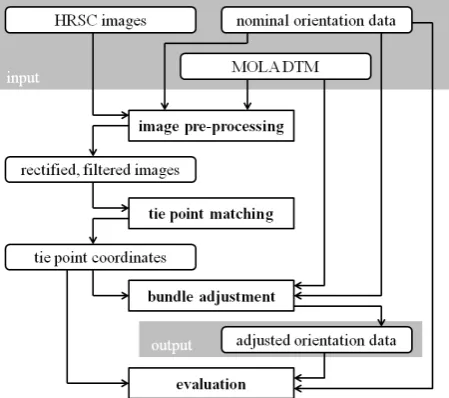
The workflow for a systematic bundle adjustment of the HRSC image data can be divided into four parts: image pre-processing, tie point matching, bundle adjustment and evaluation. In addi-tion to the HRSC images, the nominal exterior orientaaddi-tion and the Mars Orbiter Laser Altimeter (MOLA) DTM are used as in-put. The adjusted exterior orientation is the output (see Fig. 2). The use of standard parameters for each processing step allows to apply this workflow to the entire HRSC data set without manual intervention. The most relevant parameters are described in the following sections.
Figure 2: Workflow for systematic bundle adjustment of HRSC image data
2.1 Image pre-processing
The first step for the processing of single orbit strips is image pre-processing. In this step only the panchromatic channels of the HRSC images are used. Initially a low pass filter is applied to reduce image noise. A simple Gaussian with a 3x3 pixel filter matrix have shown good results and leads to a more robust tie point matching (Schmidt, 2008).
Subsequently the nominal orientation data and the MOLA DTM are used for a pre-rectification of the image data (Scholten et al., 2005). This step compensates scale differences and corrects non-quadratic pixels.
2.2 Tie point matching
In the nadir image the tie points are arranged as a regular grid. Given the desired number of points (approx. 45.000) and the im-age size a corresponding grid width is calculated. In contrast to an interest operator, the grid ensures a more regular distribution of the tie points. Tie point matching is carried out in the pre-rectified images. Depending on the image quality, the final number of suc-cessfully matched tie points lies between 20.000 and 45.000.
Each candidate point in the nadir channel image is matched with the other four panchromatic channels. Because of higher macro pixel size and consequently a lower resolution, the color channels are normally not used for photogrammetric processing.
For image matching a pyramidal approach is used to take large parallaxes and imprecise nominal orientation values into account. As similarity measure a normalized cross correlation coefficient is employed. A 35x35 pixel correlation window is used. Subse-quently the matching results are optimized by multi-image least squares matching (Schmidt et al., 2008).
2.3 Bundle adjustment
In the next part of the processing chain a combined bundle ad-justment is carried out using the image coordinates of the tie points, the MOLA DTM and the nominal exterior orientation val-ues (Spiegel, 2007a).
The used bundle adjustment method is based on the well known approach used in photogrammetry, by which the exterior orien-tation is simultaneously determined for all images. In case of HRSC the images are not acquired from individual view points but in a continuous motion. Thus, the exterior orientation must be modeled along the spacecrafts trajectory as a function of time. Three decades ago the concept of orientation points was proposed to solve this problem (Hofmann et al., 1982). Today, it is a com-mon approach in the processing of multi-line sensor data.
To fit the photogrammetrically determined 3D coordinates of a photogrammetric bundle block to a regional or global reference system, an adequate number of ground control points is normally used in aerial or spaceborne photogrammetry. For areas with-out ground control points available DTMs can be used to obtain an absolute fit (Strunz, 1993). On Mars the MOLA DTM pro-vides the best global accuracy. Therefore, a combined bundle adjustment for HRSC image data and the MOLA DTM as con-trol information was developed, implemented and tested (Spiegel, 2007b).
The general approach of the bundle adjustment is a nonlinear least-squares adjustment. This optimization aims to find the best set of unknown model parameters to explain the observations. For a combined adjustment of HRSC images and the MOLA DTM there are four types of observations: image coordinates, orienta-tion parameters, unknown bias and drift parameters to compen-sate systematic effects and DTM information. The four types of observation equations used in the bundle adjustment are de-scribed in (Bostelmann and Heipke, 2011).
The stochastic model of a bundle adjustment can be modified by changing the a priori standard deviation of a particular type of observation. This allows to handle observations as constants with
σ0 = 0, as free unknowns withσ0 → ∞or as stochastic values with aσ0of something in between. The strategy specially
devel-oped for HRSC data divides the bundle adjustment into two parts with different values for the stochastic model (Spiegel, 2007b). The image coordinates of the tie points are always introduced with an a priori standard deviation ofσ0,xy= 1µm.
In the first part only the nominal orientation parameters at the ori-entation points and the tie points are introduced, but no drift and bias and no DTM information. The a priori standard deviation for the orientation is chosen asσ0,ϕωκ = 0.028gonfor the
atti-tude andσ0,XY Z= 0.01mfor the position. The latter considers
the stable orbit of the spacecraft. This part optimizes the internal accuracy of the strip.
In the second part observations for bias and drift are introduced withσ0,bias,XY Z = 1000mallowing a translation of the whole
strip. A drift for the height component of the exterior orientation is permitted by settingσ0,drif t,Z = 0.01m/imageline. For X
bias nor drift are considered. This modification of the stochastic model allows to fit the HRSC object points to the MOLA DTM, which is introduced withσ0,DT M= 100mfor the terrain points.
In this part the absolute position of the image strip is adjusted in an iterative way.
Both parts use blunder detection. In the first part blunders in the tie points are detected iteratively by analyzing the residuals. In the second part the difference between the MOLA surface and the HRSC points is used to find non-fitting points (Spiegel, 2007b).
2.4 Evaluation
To evaluate the performance of the bundle adjustment, the quality of the nominal and adjusted exterior orientation data is compared. Because of the large amount of data, a single value describing the geometric quality is easier to handle for systematic analysis of the whole data set. The mean forward ray intersection error sum-marizes the accuracy of all object points and is a good measure for the internal consistency of the data (Gwinner et al., 2009). The evaluation step calculates the forward intersection error for all object points twice. Both times it uses the same set of tie point coordinates and only switches between nominal and adjusted ori-entation data, so that the resulting mean intersection error reveals the gain in quality.
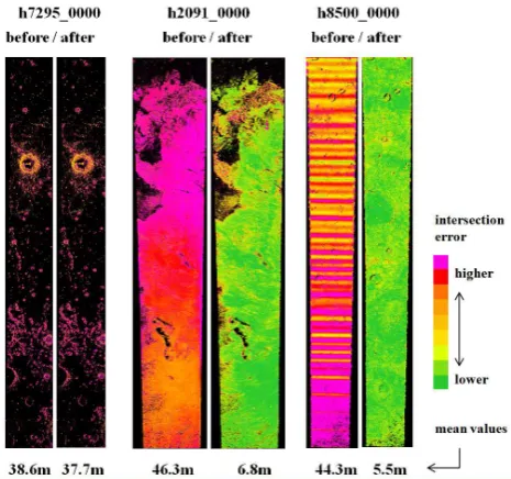
Additionally, both the nominal and the adjusted orientation in-formation is used to generate dense 3D point clouds as used for DTM generation (Gwinner et al., 2010). The intersection error for all these points is used to plot two color coded error maps. This allows a visual inspection of the spatial distribution and ac-curacy of the HRSC points. Fig. 3 shows three examples of er-ror maps. Strip h7295 0000 displays large black areas where the dense matching algorithm was not able to find conjugate image points. The color of the small number of points, shows a low accuracy. There is no significant improvement through bundle adjustment. This is also indicated by the values for the mean in-tersection error (38.6m and 37.7m). In contrast, the error maps and mean intersection error of h2091 0000 and h8500 0000 show considerable improvement after bundle adjustment despite of the high frequent oscillations visible in strip h8500 0000.
Figure 3: Error maps with mean intersection error of the object points (black: no points)
3 MULTI ORBIT BLOCKS
For the processing of photogrammetric blocks containing images from more than one HRSC strip an adaption of the same work-flow for single orbit strips (Fig. 2) can be used (Spiegel, 2007b).
To efficiently process large image blocks a suitable strategy has to be set up. It is not reasonable to process all image strips of the entire block together because only neighboring image strips overlap. Therefore, the whole image block is broken down into smaller sub-blocks which additionally opens up the advantage of parallel processing. If a sufficient number of server nodes re-spectively CPU cores is available, it is possible to run three of the four processing parts (image pre-processing, tie point matching and evaluation) for all sub-blocks simultaneously. This drasti-cally saves computation time.
For the tie point matching each sub-block needs a reference im-age which is matched against all other overlapping imim-ages. Every strip of the entire block has to supply this reference image once. If e.g. the block consists of two overlapping strips with ten sin-gle images in total the nadir channel of the first strip is matched against all other nine images. The second sub-block in this exam-ple would simply consist of the second strip. At this point merely the remaining area which was not captured by the first strip is covered.
Figure 4: Concept of sub-blocks using the example of three strips, green: 5-ray points, red: 10-ray points
This strategy on the basis of three overlapping strips is depicted in Fig. 4. Three sub-blocks are built up in the combinations 1 & 2, 2 & 3 and 3 separately. An advantage of this approach in particular with strips of inhomogeneous geometry is that for each sub-block an optimal average matching scale can be defined. In case of processing all image strips simultaneously an average matching scale for the complete block would have to be found.
Concerning computational limitations the number of tie points per sub-block has to be limited. Tests have shown that if a suf-ficient number of tie points in all overlapping areas is available, a further increase of the number of points does not improve the results. While it is clear that this strategy will fail for crossing strips as to be found e.g. on the poles it is good compromise with regard to computing power.
In the subsequent bundle block adjustment the results of the sub-blocks are imported and processed simultaneously. As approxi-mate values of the exterior orientation for the pre-rectification of the images the results from single orbit strip processing are used. The reason is that while images of one strip normally exhibit a high relative accuracy, the discrepancy between neighboring im-age strips can reach several hundred meters which would require very large search spaces for matching. When employing adjusted image strips the orbits fit much better among each other so that smaller search spaces can be used.
afterwards also in the overlapping areas. Again, the blunders are detected firstly in ray intersections only, and secondly with refer-enc to the MOLA DTM (Spiegel, 2007b).
For the evaluation of the bundle adjustment results the mean inter-section error is calculated only for point lying in an overlapping area. This reveals the improvement of the bundle adjustment of blocks more clearly than the usage of all points of a sub-block would do.
4 RESULTS
4.1 Systematic bundle adjustment of single orbit strips
The method for systematic bundle adjustment of single orbit strips was used to process the HRSC data received in the almost 7 years from January 2004 until November 2010. During this time the Mars Express mission has surrounded the planet 8761 times. In about 2800 of these orbits the camera took imagery theoretically suitable for stereo processing. HRSC image data sets of 2535 strips were succesfully processed. In 2329 strips (91.9%) the ex-terior orientation was significantly improved by the bundle ad-justment. For a number of 123 strips further improvements of the exterior orientation were achieved by modeling spacecraft oscil-lations through a shorter orientation point distance (Bostelmann and Heipke, 2011).
Figure 5: Number of strips grouped by their mean intersection error before (light gray) and after (dark gray) the improvement of the exterior orientation by bundle adjustment
In Fig. 5 the mean intersection error for a total of 2535 suc-cessfully processed strips is presented. The strips are classified according to their intersection error in ranges of10m. The light gray bars represent the quality of the exterior orientation data be-fore, and the dark gray bars after the process of bundle adjust-ment. It is shown that the number of strips with a mean intersec-tion error<10mdistinctly increases after the bundle adjustment (more precisely from 47 to 437). Also the quantity of strips with a mean intersection error lying between10mand20mincreases by a number of 200. On the other hand the number of strips with higher errors obviously decreases. E.g. the number with an er-ror>100mis reduced from 119 to 38 strips. Probably because there was no exclusion of strips with obvious image degradation, the mean intersection errors presented here are somewhat higher than in other statistics of HRSC DTM processing (e.g. Gwinner et al., 2010). In general the mean intersection error presented in this paper should not be taken as an absolute criterion for the quality of HRSC data, but it is a good indicator for a relative im-provement.
4.2 Multi orbit block processing
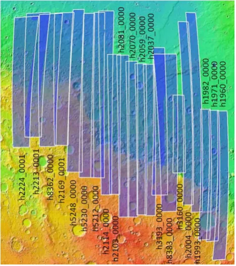
The analysis of single orbit strips reveals the internal photogram-metric accuracy of HRSC image data. To connect different strips to a stable block, in addition a sufficient number of accurate tie points in the overlapping area is needed. The previously de-scribed method of adjusting the exterior orientation of a block was used for a set of 21 overlapping HRSC strips. The selected area is a region called Nepenthes Mensae between 1◦S to 17◦N and 111◦E to 135◦E. The footprints of the nadir channel images are shown as an overlay to the color coded MOLA DTM in Fig. 6.
Figure 6: Color coded MOLA DTM with footprints of 21 HRSC nadir channel images constituting a photogrammetric block
The criteria for the selection of these strips were:
• The 21 strips overlap to form a single block.
• All five panchromatic channels are available.
• The single strip bundle adjustment succeeded with a small mean intersection error (less than20m).
• The resolution of the nadir channel is better than30m.
• The image information allows tie points distributed over the whole image.
• The overlapping area between neighboring strips is rela-tively wide.
HRSC Strip Date Nadir Resolution [m] h2224 0001 2005-10-07 20.9 - 31.6 h2213 0001 2005-10-04 20.5 - 30.4 h8362 0000 2010-07-15 19.8 - 29.2 h2169 0001 2005-09-22 16.3 - 24.3 h5248 0000 2008-02-02 13.7 - 18.7 h5230 0000 2008-01-28 13.3 - 17.5 h5212 0000 2008-01-22 13.1 - 16.3 h2114 0000 2005-09-06 12.2 - 18.7 h2103 0000 2005-09-03 12.0 - 15.7 h2081 0000 2005-08-28 11.6 - 14.4 h2070 0000 2005-08-25 11.6 - 13.7 h2059 0000 2005-08-22 11.6 - 13.2 h2037 0000 2005-08-16 12.2 - 12.7 h3193 0000 2006-07-05 13.8 - 18.5 h8383 0000 2010-07-21 18.3 - 28.2 h3160 0000 2006-06-26 13.2 - 15.1 h2004 0000 2005-08-06 12.8 - 12.6 h1993 0000 2005-08-03 13.4 - 12.5 h1982 0000 2005-07-31 14.8 - 12.1 h1971 0000 2005-07-28 15.5 - 12.4 h1960 0000 2005-07-25 17.2 - 12.6
Table 1: HRSC strips used for the block
Figure 7: Mean intersection error before and after single strip bundle adjustment
For the stability of the complete block the spatial accuracy of tie points in the overlapping areas is important. Hence for all 20 sub-blocks with an overlapping area the mean intersection error was calculated using the different orientation data sets (Fig. 8).
For the computation of the complete block as a whole, the number of tie points for each sub-block was reduced to a target value of 8.000.
In all but one sub-block the block adjusted orientation data show a clearly higher accuracy for the HRSC points in the overlapping area than orientation data adjusted for single strips. In sub-block h2169-h5248 the overlapping area is too small to find a sufficient number of tie points. All sub-blocks with a mean intersection error notably higher than10mconsist of two image strips with different illumination conditions (Fig. 9).
Overall the adjustment of the exterior orientation in a regional block does not only provides results with a high internal accu-racy for each strip, but also the relative orientation of the strips is clearly improved. Additionally the block as a whole is fitted to a global reference system, the MOLA DTM. The block adjusted orientation data are the most appropriate ones for the subsequent derivation of a DTM mosaic or the rectification of ortho-images
Figure 8: Mean intersection error for overlapping areas in sub-blocks calculated with different orientation values
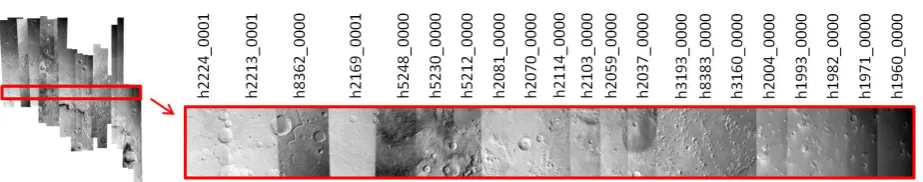
(Dumke et al., 2008). For the depicted example of 21 image strips, the HRSC DTM mosaic is shown in Fig. 10.
Figure 10: Shaded relief of a HRSC DTM mosaic generated with the block adjusted orientation data
5 CONCLUSIONS AND FUTURE WORK
The workflow for systematic bundle adjustment of HRSC image data was used to improve the exterior orientation of single strips and a regional block. It has been shown that for 2329 single strips a significant improvement was achieved. A block comprising 21 HRSC strips was simultaneously adjusted and the results were evaluated to demonstrate the stability of the overlapping areas.
Figure 9: Illumination differences in the orthoimage mosaic rectified with the block adjusted orientation data and the HRSC DTM mosaic
REFERENCES
Bostelmann, J. and Heipke, C., 2011. Modeling spacecraft oscil-lations in HRSC images of Mars Express. International Archives of Photogrammetry and Remote Sensing, 38 (4/W19), Hannover.
Dumke, A., Spiegel, M., Schmidt, R., Michael, G. and Neukum, G., 2008. Mars: High resoluition digital terrain model and ortho-image mosaic on the basis of MEX/HRSC data. Interna-tional Archives of Photogrammetry and Remote Sensing 37(4), pp. 1037–1042.
Gwinner, K., Scholten, F., Preusker, F., Elgner, S., Roatsch, T., Spiegel, M., Schmidt, R., Oberst, J., Jaumann, R. and Heipke, C., 2010. Topography of Mars from global mapping by HRSC high-resolution digital terrain models and orthoimages: Characteristics and performance. Earth and Planetary Science Letters 294(3-4), pp. 506–519.
Gwinner, K., Scholten, F., Spiegel, M., Schmidt, R., Giese, B., Oberst, J., Heipke, C., Jaumann, R. and Neukum, G., 2009. Derivation and Validation of High-Resolution Digital Terrain Models from Mars Express HRSC-Data. Photogrammetric En-gineering & Remote Sensing 75(9), pp. 1127–1142.
Hofmann, O., Nave, P. and Ebner, H., 1982. DPS - A Digital Photogrammetric System for Producing Digital Elevation Mod-els and Orthophotos by Means of Linear Array Scanner Imagery. International Archives of Photogrammetry and Remote Sensing 24 (3), pp. 216–227.
Neukum, G., Jaumann, R. and the HRSC Co-Investigator Team, 2004. HRSC: The High Resolution Stereo Camera of Mars ex-press. Mars Express: The Scientific Payload, Eur. Space Agency Spec. Publ., ESA-SP 1240, pp. 17–36.
Schmidt, R., 2008. Automatische Bestimmung von Verkn¨upfungspunkten f¨ur HRSC-Bilder der Mars Express-Mission. Dissertation, DGK-C, Nr. 623, Deutsche Geod¨atische Kommission, M¨unchen.
Schmidt, R., Spiegel, M., Heipke, C., Dumke, A., Neukum, G. and the HRSC Co-Investigator Team, 2008. Operational Determi-nation of Tie Points and Bundle Adjustment of HRSC Images of the Mars Express Mission. International Archives of Photogram-metry and Remote Sensing 37(4), pp. 1025–1030.
Scholten, F., Gwinner, K., Roatsch, T., Matz, K., Wahlisch, M., Giese, B., Oberst, J., Jaumann, R. and Neukum, G., 2005. Mars Express HRSC Data Processing-Methods and Operational Aspects. Photogrammetric Engineering and Remote Sensing 71(10), pp. 1143–1152.
Spiegel, M., 2007a. Improvement of Interior and Exterior Ori-entation of the Three Line Camera HRSC with a Simultaneous Adjustment. International Archives of Photogrammetry and Re-mote Sensing 36(3/W49B), pp. 161–166.
Spiegel, M., 2007b. Kombinierte Ausgleichung der Mars Ex-press HRSC Zeilenbilddaten und des Mars Global Surveyor MOLA DGM. Dissertationsschrift, DGK-C, Nr. 610, Deutsche Geod¨atische Kommission, M¨unchen.
Strunz, G., 1993. Bildorientierung und Objektrekonstruktion mit Punkten, Linien und Fl¨achen. Dissertationsschrift, DGK-C, Nr. 408, Deutsche Geod¨atische Kommission, M¨unchen.
ACKNOWLEDGEMENTS