ULTRAMAP V3
–
A REVOLUTION IN AERIAL PHOTOGRAMMETRY
B. Reitinger, M. Sormann, L. Zebedin, B. Schachinger, M. Hoefler, R. Tomasi, M. Lamperter, B. Gruber, G. Schiester, M. Kobald, M. Unger, A. Klaus, S. Bernoegger, K. Karner, A. Wiechert, M. Ponticelli, M. Gruber
Microsoft Photogrammetry, Graz, Austria [email protected]
Commission IV, WG IV/3
KEY WORDS: UltraMap, dense matching, semi-global matching, ortho mosaicking, ortho processing.
ABSTRACT:
In the last years, Microsoft has driven innovation in the aerial photogrammetry community. Besides the market leading camera technology, UltraMap has grown to an outstanding photogrammetric workflow system which enables users to effectively work with large digital aerial image blocks in a highly automated way. Best example is the project-based color balancing approach which automatically balances images to a homogeneous block. UltraMap V3 continues innovation, and offers a revolution in terms of ortho processing. A fully automated dense matching module strives for high precision digital surface models (DSMs) which are calculated either on CPUs or on GPUs using a distributed processing framework. By applying constrained filtering algorithms, a digital terrain model can be derived which in turn can be used for fully automated traditional ortho texturing. By having the knowledge about the underlying geometry, seamlines can be generated automatically by applying cost functions in order to minimize visual disturbing artifacts. By exploiting the generated DSM information, a DSMOrtho is created using the balanced input images. Again, seamlines are detected automatically resulting in an automatically balanced ortho mosaic. Interactive block-based radiometric adjustments lead to a high quality ortho product based on UltraCam imagery. UltraMap v3 is the first fully integrated and interactive solution for supporting UltraCam images at best in order to deliver DSM and ortho imagery.
1. INTRODUCTION
In the last years, Microsoft has often demonstrated innovation in the photogrammetry community. The latest innovation was the launch of the new flagship the “UltraCam Eagle” (Wiechert, Gruber, & Ponticelli, 2011). UltraMap, which is the software workflow system for the UltraCam, has also shown cutting edge technology in the past. One example is the project-based colour balancing, which is able to automatically remove physically based colour artefacts taking a block’s geometry into account.
With the new UltraMap v3, we introduce a fully automated processing pipeline which allows processing UltraCam imagery to a digital surface model (DSM) including a DSMOrtho (ortho mosaic based on an automatically generated DSM). In addition, we offer a traditional ortho mosaic, which we call a DTMOrtho. A further output of our pipeline is a 3D point cloud, which is able to deliver a very high point density per square meter.
By exploiting the latest Microsoft’s developments, we are able to deliver a very high quality DSM which strives for high accuracy without any manual interaction. Since our ortho mosaicking approach takes into account all available inputs (i.e. a DSM and also an automatically generated DTM), UltraMap v3 is able to generate seamlines at desired paths (i.e. avoid passing through houses); remaining seamline editing for challenging regions are fixed by exploiting our DragonFly technology (Reitinger, Hoefler, Lengauer, Tomasi, Lamperter, & Gruber, 2008). DragonFly is a responsive visualization engine for quality control and interaction with user experience
for working with large image blocks. Figure 1 UltraMap v3 processing pipeline.
International Archives of the Photogrammetry, Remote Sensing and Spatial Information Sciences, Volume XXXIX-B4, 2012 XXII ISPRS Congress, 25 August – 01 September 2012, Melbourne, Australia
Figure 1 shows a brief overview of our UltraMap v3 processing pipeline. The RawDataCenter is responsible for processing the UltraCam imagery into a so-called Level-2 data format. This data contains the digital negative of the camera (radiometrically and geometrically calibrated). The Aerial Triangulation (AT) module is responsible for calculating image correspondences in order to generate a precise exterior orientation for a whole image block. The Radiometry module is used to remove any physically-based colour artefacts as well as to adjust the desired final colour tone.
The DSM Generation module takes the Level-2 images including the precise exterior orientation information and generates per-pixel height values. The final Ortho Generation module takes all available inputs (i.e. Level-2 imagery, AT result, radiometric settings, and the DSM/DTM) in order to generate the final ortho mosaic.
The paper is organized as follows: after a brief related work section about semi-global matching and ortho mosaicking, the technical part of the UltraMap v3 system including dense matching, ortho mosaicking, user interaction, and distributed processing is explained. Before showing some results, we also outline our processing environment including some words about the interactive visualization.
2. RELATED WORK
The first part of the UltraMap v3 is the generation of a digital surface model. Semi-global matching is a known technique in the photogrammetry community. In 2011, Heiko Hirschmueller (Hirschmueller, 2011) presented a good overview about the semi-global matching strategy including different applications. His approach can be seen as the current state-of-the-art technique for processing aerial imagery. Another comparable approach in the computer vision community can be found in Klaus et al. (Klaus, Sormann, & Karner, 2006). This method was leading the Middleburry stereo evaluation ranking for a long period of time (http://vision.middlebury.edu/stereo/eval/).
Related research in the field of ortho image mosaic generation can be found in the area of visual analysis, which has been well studied in computer graphics, computer vision and photogrammetry. Amhar et al. (Amhar & Ecker, 1996) proposed a methodology, which is based on photogrammetric principles to create DSMOrtho images from digital terrain models. Korytnik et al. (Korytnik, Kuzmin, & Long, 2004) proposed a polygon-based approach for the detection of occluded areas during the DSMOrtho image generation. In contrast to the method of Korytnik et al., most of other existing DSMOrtho image generation approaches are based on the Z-buffer algorithm, e.g. Chen et al. (Chen, Rau, & Chen, 2002) and Zhou (Zhou, 2004). Another closely related research is the well-studied problem of image stitching and compositing by Uyttendaele et.al. (Uyttendaele, Eden, & Szeliski, 2006), (Uyttendaele, Szeliski, & Steedly, 2011). Uyttendaele et al. propose a graph cut based approach for finding seams between overlapping areas and furthermore apply Poisson blending for compositing the final image.
3. FULLY AUTOMATED ORTHO PIPELINE
3.1 Dense matching and fusion
Dense matching is the process of finding corresponding pixels in a pair of images in order to do a 3D reconstruction. As a prerequisite, the exterior orientation and the intrinsic calibration
of the camera must be known. In order to establish correspondences, image-based correlation methods are used (e.g. normalized cross correlation). The output of the stereo dense matching approach is a range image which stores the calculated disparity values of a single image pair.
The next step is to perform a range image fusion which takes all generated range images and calculates on the one hand side a 3D representation (i.e. a point cloud), and finally a 2.5D height field known as the digital surface model. The range image fusion can be formulated as a global optimization step minimizing an objective function.
DTM filtering
The generated DSM can further be post-processed by applying a constrained filter operation. A gradient-based approach allows us to filter out buildings while preserving hills. The generated DTM is then used to generate a DTMOrtho in a fully automated way.
3.2 Ortho rectification
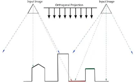
The first step in the ortho pipeline is called ortho rectification which re-projects the input images on a defined proxy geometry. Therefore, we introduce a virtual camera which is defined as a three dimensional plane emitting parallel rays to the ground (compare Figure 2). Those rays are intersected with the scene and therefore generate a 2.5D surface. In Figure 2, the upper half depicts two input images and the ortho projection whereas the 2.5D height field profile or surface is illustrated at the bottom. The process of generating an image from a new viewpoint is also known as image-based rendering. Due to the fact that one input image can only cover a certain area of the ortho projection, some regions are occluded (i.e. tall buildings). These regions are then filled by using neighbouring image information.
Figure 2 Concept of an ortho projection with two input images.
3.3 Seamline generation
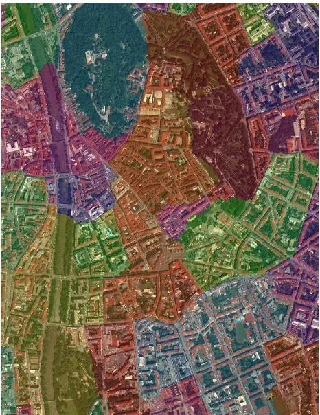
After the ortho rectification process, the next step is to find seamlines between projected ortho patches. This step is also known as contribution mask generation, since the contribution mask is the dual structure to the seamlines (see Figure 3). Seams correspond to transitions from one input image to another one. This process can be defined as an objective function, where the minimization can be reformulated as a function of the sum of unary and binary costs. This function incorporates the viewing angle of the input image including the colour differences. The optimization for finding the best path is done by applying a graph-cut (Kolmogorov & Zabih, 2004) algorithm.
International Archives of the Photogrammetry, Remote Sensing and Spatial Information Sciences, Volume XXXIX-B4, 2012 XXII ISPRS Congress, 25 August – 01 September 2012, Melbourne, Australia
Figure 3 Example for a contribution mask being color coded.
3.4 Ortho compositing
Once all pixel information in the ortho image mosaic is known, it is necessary to blend them together in order to create a visual appealing result. Although project-based colour balancing is applied to the input images, a final smooth blending is still necessary. For smooth blending of the tile patches, we use the proposed method by Uyttendaele et al. (Uyttendaele, Szeliski, & Steedly, 2011). They presented a technique for fast Poisson blending and gradient domain compositing.
4. PROCESSING ENVIRONMENT
Since the UltraMap v3 processing pipeline is very resource intensive, our approach offers support for different processing environments. On the one hand side, the complete DSM/ortho pipeline can be processed on scalable CPU-only machines, and on the other hand side the dense matching can also run on dedicated GPU nodes. The latter delivers high speed-ups because the dense matching is best suitable for a SIMD architecture such as graphics cards. Figure 4 shows a potential configuration of an UltraMap v3 system. The newly introduced V3 machines (which are resource intensive machines) strive for high performance, since an entire machine can be used to work on one task at a time. The existing V2 machines share their processing power with different tasks running on the same machine. The V3 machines can either be configured as CPU-only or as GPU-enabled nodes.
The front-end machine is used to interact with the data and is not designed for processing. A very import part of the processing environment is the network which is required to transfer the data most efficiently between processing nodes and disk storage.
Figure 4 Example for the UltraMap v3 processing environment.
5. VISUALIZATION AND INTERACTION
5.1 DragonFly Technology
Since the beginning of UltraMap, DragonFly is the technology which is used to interact with large amount of UltraCam image data (Reitinger, Hoefler, Lengauer, Tomasi, Lamperter, & Gruber, 2008).
DragonFly is based on a technology called Seadragon which is a Microsoft technology also built-in into other products (e.g. DeepZoom, Zoom-It, or Photosynth). For UltraMap v3, we introduce some more extensions and enhancements of the existing DragonFly technology. On the one hand side, we worked on optimization and improved user experience in order to have a smooth rendering of the processed ortho tiles. On the other hand side, we are able to exchange image content on the fly. This is required for any modification on the image data (i.e. modifying the DSM/DTM or the contribution mask).
The ortho application which is the main user interface for working with ortho data uses DragonFly for visualizing all data generated. By exploiting shader code on the graphics card, we are able to interactively blend between the DSMOrtho and the DSM. This allows for quick quality controls and data interpretation while evaluating the quality of the dense matching result. The shader is also used to control the final radiometric tone of the image block. Another feature of using shader code is to do relief shading based on DSM data (Figure 5).
Figure 5 On-the-fly relief shading of a generated DSM which is one feature of the DragonFly technology (data courtesy of Ordnance Survey, UK).
International Archives of the Photogrammetry, Remote Sensing and Spatial Information Sciences, Volume XXXIX-B4, 2012 XXII ISPRS Congress, 25 August – 01 September 2012, Melbourne, Australia
6. RESULTS
The UltraMap v3 ortho processing algorithms already show up a long testing and production phase. In the last years, Microsoft produced a full US coverage and almost a complete European coverage of 30cm ortho imagery based on UltraCam technology. The joined project “Clear 30” between Microsoft and DigitalGlobe was a big commitment in generating high quality maps for most parts of the world.
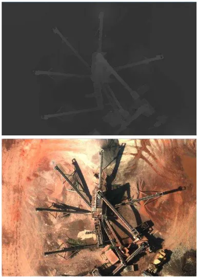
In addition, we already applied our software on customer data which have been kindly provided for testing. Figure 6 shows an example of a DSM and DSMOrtho provided by City of Graz. The presented dense matching approach allows for reconstructing the fine crane structures. The conveyors are shown with precise and sharp edges exploiting the redundancy of the imagery (flown with a UC-Xp at 3cm GSD and with an overlap of 60/60).
Figure 7 shows an example of a DTMOrtho which was also generated in an automated way without any user interaction. This imagery was provided by Ordnance Survey, UK. This dataset was also flown with a UC-Xp at 10 cm ground resolution. The DTMOrtho was projected on an internally generated DTM using the presented constrained filter approach.
Figure 6 DSM and DSMOrtho screenshot showing a gravel pit (data courtesy of City of Graz).
6.1 Processing Time
We have processed a demo dataset on our reference system. The system consists of 4 machines each of which has 4 NVIDIA Tesla cards built-in. Each machine has an i7 6 core processor with 3.3 Ghz and 32 GB RAM. Our test dataset has 408 UltraCam Xp input images (each of which has an image resolution of 17310x11310 pixels) and was processed on all 4 machines in parallel. The total processing time for generating the DSM, DSMOrtho, and the DTMOrtho (without calculating the time for Level-2 processing and aerial triangulation) was less than 24 hours.
Figure 7 DTMOrtho showing a main junction without any distortions (data courtesy of Ordnance Survey, UK).
Processing type Time [min]
DSM 190
DSMOrtho 546
DTM 39
DTMOrtho 661
7. REFERENCES
Amhar, F., & Ecker, R. (1996). An integrated solution for the problems of 3d man-made objects in digital orthophotos. International Archives of Photogrammetry and Remote Sensing, (pp. 84-89). Chen, N., Rau, J., & Chen, L. (2002). True orthophoto
generation built-up areas using multi-view images. Photogrammetric Engineering Remote Sensing, 6, pp. 68-74.
Gruber, M., & Reitinger, B. (2008). UltraCamX and a new way of photogrammetric processing. ASPRS 2008 Annual Convention. Portland, Oregon.
Hirschmueller, H. (2011). Semi-Global Matching - Motivation, Developments and Applications. Photogrammetric Week '11, (pp. 173-184). Stuttgart.
Klaus, A., Sormann, M., & Karner, K. (2006). Segment-Based Stereo Matching Using Belief Propagation and a Self-Adapting Dissimilarity Measure. ICPR, (pp. 15-18). Kolmogorov, V., & Zabih, R. (2004). What energy functions
can be minimized via graph cuts? IEEE PAMI, 26(2), 147-159.
Korytnik, P., Kuzmin, P., & Long, O. (2004). Polygon-based true orthophoto generation. ISPRS:C1, (pp. 529-531). Istanbul, Turkey.
Reitinger, B., Hoefler, M., Lengauer, A., Tomasi, R., Lamperter, M., & Gruber, M. (2008). Dragonfly - Interactive Visualization of Huge Aerial Image Datasets. International Archives of Photogrammetry, Remote Sensing And Spatial Information Science, 31st Congress in Beijing, (pp. 491-494). Beijing.
Uyttendaele, A., Eden, A., & Szeliski, R. (2006). Seamless image stitching of scenes with large motions and exposure differences. CVPR, 2, pp. 2498-2505. Uyttendaele, M., Szeliski, R., & Steedly, D. (2011). Fast
poisson blending using multi-splines. International Conference on Computational Photography. Wiechert, A., Gruber, M., & Ponticelli, M. (2011). UltraCam
Eagle, the new Super-Large Format Digital Aerial Camera. Proceedings of the American Society for Photogrammetry & Remote Sensing. Milwaukee, WI. Zhou, G. (2004). Urban large-scale orthoimages standard for
national orthophoto program. IEEE International Geoscience and Remote Sensing Symposium, 1, pp. 25-29.
International Archives of the Photogrammetry, Remote Sensing and Spatial Information Sciences, Volume XXXIX-B4, 2012 XXII ISPRS Congress, 25 August – 01 September 2012, Melbourne, Australia