A TOPOLOGICAL FRAMEWORK FOR THE TEMPORAL ASPECTS OF LANDFORM
DEVELOPMENT
M.-O. Löwner a, *, T. Becker b
a
Institute for Geodesy and Photogrammetry, Technische Universität Braunschweig, Germany - [email protected]
b Institute for Geodesy and Geoinformation Science, Technische Universität Berlin, Germany -
Commission II, WG II/2
KEY WORDS: 3D Data Models, Landform Development, 4D Modelling, Dual Graph Structures, Poincaré Duality, GML
ABSTRACT:
Natural landforms are of great importance for a variety of scientific and engineering disciplines. Investigation of landforms can be improved by comparison of features that have similar characteristics, structure and genesis. We propose a novel framework for the representation of the temporal aspects of landform development that simplifies the complex spatial relationships between 3D objects and the modelling of geological processes over time (4D) applying the Poincaré Duality. Single landform layers are represented as nodes (DualStructures) and the neighbourhood of these layers are represented as edges (DualStructureRelations). Finally, a DualStructureState represents a whole landform of stable conditions over a period of time. Change of a landform is represented as additional edges (Abstract_GeoProcess) between the nodes of different layers. The overall structure constitutes a multilayer graph, where all the nodes from all N layers are included but are separated into N partitions of time. All dual representations may be associated with geometric and semantic representations, if available. A formal data model on natural landforms focusing on topological representation is a major step towards the interoperable exchange and comparison of scientific results on landforms. Concerning existing models, our framework can be considered as a superset with regard to model expressivity. This will improve the possibilities to exchange or link data between different application fields.
* Corresponding author.
1. INTRODUCTION
Natural landforms and geological structures play an important role for a variety of scientific and engineering disciplines. As natural landforms build up the surface and subsurface environment, society interacts with them in a complex way. Earth scientists and civil engineers working on these issues need GI technologies to make results on landforms, its internal structure, its genesis and future development reliable and comparable.
Landforms are unique in terms of their internal structure, their topological relation to other landforms and their temporal changes as well as their exposure to climate system. Therefore, the history, internal state and future behaviour of a landform cannot be analysed by simple mathematical formulas or even complex physical models. Thus, landforms are examined and rated individually. This includes the analysis of the genesis of a landform as one major key for future behaviour.
According to Dikau (1999) investigation of landforms includes first, time represented by the stratigraphic record of the underground material and, second, the spatial distribution of landforms. The latter clearly refers to a topological description of landforms that may help to compare different natural systems. This landform assemblage has also been identified by (Pike and Dikau, 1995 and Brunsden, 1996) as an important character of geomorphic systems. As a third method of examination Dikau (1999) identified the substitution of a landform developing process sequence by a spatial association of recent landforms or landform components, which is called the ergodic principle. The principle of ergodic reasoning, in which space is substituted for time, is an applicative method to
describe and predict future behavior of a landform comparing it with others. Since landforms are unique, objects of comparison must have at least similar characteristics, structure or genesis with historical landforms that once encountered similar behaviour in the past. One of the classic examples of this type of research is provided by (Welch, 1970; Brunsden and Kesel, 1973). This research can be effectively supported by geo information technology and a proportionate representation of landforms within a geospatial database. As a last point, Dikau (1999) identifies the principle of actualism which is based on the transformation of processes acting under recent climatic conditions into a past environment for which the same climate is inferred.
Landforms do not exist in isolation but do interact with others. Their specific association builds up the so called georelief (Kugler, 1974; Dikau, 1996) and characterizes a specific geomorphic system. While single landforms are scale-dependent, the composition of a geomorphic system follows a spatial hierarchy (Ahnert, 1988; Dikau, 1989; Brunsden, 1996). Smaller landforms are located on the top of larger ones and cover them partly. Therefore, size is a good indicator of a landform’s lifetime and age (Ahnert, 1996).
Like a single landform, the association of many depends on internal system states, material supply and external driving forces. Following this experience, analysing the composition of landform association allows scientists to understand the main processes reworking a system, the succession of these processes in the past and probable developments in the future.
A lot of the landform’s interaction may be analysed using the concept of topology. First, this includes the chance of processes
ISPRS Annals of the Photogrammetry, Remote Sensing and Spatial Information Sciences,
to transport material from one landform to another one. Identifying possible material sources is the first step to expose and explain existing sediment cascades of a geomorphic system. Second, topological investigation may help to identify the chronological order in which landforms were formed (Löwner, 2013). Often, this non-metric or relative dating is an important step towards the understanding of a geomorphic system. Today, there is no comprehensive interoperable data model to represent semantics, geometry and topology of landforms. Due to their complex construction and characteristics and their interrelation with other landforms within a natural system, defining a semantic data model is a reasonable challenge. Another problem is the integration of field based data representation in conjunction with the well-known boundary representation (Requicha, 1980). The latter can easily applied on manmade features like buildings with crisp boundaries as shown in CityGML (Gröger et al., 2012). Landforms on the one hand are divided by layers that have crisp boundaries but are hard to detect. On the other hand some ‘boundaries’ reveal a smooth transition. However, even if no correct and complete geometry is available, semantic information, topological relation and change can be represented.
Here we propose a 4D data model that integrates topological representation of natural landforms with geometric and semantic description. Since topology can be applied to represent sequences of geologic layers and neighbourly relations of landforms, exact geometric representation can be neglected without the loss of substantially information. Nevertheless, geometric representation is still possible. We combine a Multilayered Graph Model proposed by Becker et al. (2008) with a GML-based application model for natural geoobjects (Löwner, 2008; 2010). Within this framework it is possible to represent landforms in an object-oriented view that comprises a true 3D geometric data representation, semantic description and topological interrelations and the change of all these description in time. A formal data model on natural landforms focusing on topological representation is a major step towards the interoperable exchange and comparison of scientific results on landforms.
In section 2 we review related work with focus on the two models we combined to represent landforms. Section 3 is devoted to a living example of slope developed under different processes over a period of 10.000 years as a use case for the model proposed in section 4. In section 5 we show the representation of a loess covered slope similar to the use case and its genesis as an example. We will follow up with a discussion and an outlook.
2. RELATED WORK
Modelling 3D phenomena has been subject to substantial work of many scientists. This includes the geometrical modelling of 3D subsurface space, the introduction of topological analysis and the introduction of semantic data models.
Jones (1989) reviewed still valid 3D representations of space including block models, voxels and octrees as well as the boundary representation. Since an octree can be viewed as 3D tessellation all the subsurface space has to be represented. On the other hand, boundary representation needs precise information of crisp boundary surfaces. Regarding drilling data, these can often be found.
Based on Egenhofer’s 9-intersection model (Egenhofer and Herring, 1992) Zlatanova (2000) identified eight relations of bodies in ℝ3 by negative conditions that are possible in reality.
Löwner (2012) proved four of these relations (disjoint, contains,
inside, meets) and another relation incorporating a third, conjunctive body as important for the description of geomorphic situations. According to that, topological relationships of landforms can directly be related to geomorphic insights. This includes a process-related accessibility of landforms by material transport processes and therefore material properties as well as the chronological order of landform creation.
Emgård and Zlatanova (2008a; 2008b) and Tegtmeier et al. (2009) point out the need for an integrated semantic information model that includes objects above and on the surface as well as subsurface objects and, in particular, subsurface geological and geotechnical objects. They propose a model called 3DIM – 3D Integrated Model. Their superclass BelowSurfaceObject is further subdivided into BelowSurfaceSpace, Geology, Water and BelowSurfaceUtilitiy. Geology again is further subdivided into Layers (LayerRock, LayerStrongSoilWeakRock and LayerSoil), Obstacles, Cavity, and Reservoir. However, next to general geological information, the main focus of this model is for infrastructural construction processes. Thus, it lacks of topological relations between Layers and, further, the description of geomorphological processes is not possible.
2.1 An application model for natural geoobjects and their topology
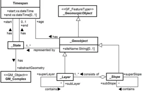
A GML based application model for representing natural geoobjects has been proposed by Löwner (2008; 2010). Herein, an abstract class _Geoobject represents a solid landform feature as a particular spatial unit of the landsurface. The class has no class attributes describing the landform but one or more association to an abstract class _State. For an associated Timespan the _State acts as an agent between the _Geoobject and its properties including geometry and attributes (Figure 1). The latter is modelled by an abstract class _AttributeSet, which is not depicted here.
Figure 1. The abstract class _Geoobject represented by a time-dependent geometry and attributes (not depicted here) (Löwner,
2008, modified).
A _Slope as a synonym for landform is a specialisation of the abstract class _Geoobject. Referring to the geomorphologists Dalrymple et al. (1968) and Caine (1974) a _Slope may again contain _Slopes. A _Slope consists of one or more abstract classes _Layer, i.e. a soil layer which itself is a _Geoobject with all associated classes. Such a _Layer may contain one or more subLayers. Because _Layer is derived from _Geoobject, it exhibits the association to a _State, too.
Landforms are subject to change due to external forces resulting in material transporting processes. This fact is modelled
ISPRS Annals of the Photogrammetry, Remote Sensing and Spatial Information Sciences,
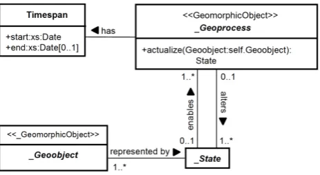
introducing an abstract class _Geoprocess that may connect two instances of a _Geoobject initializing new instances of the corresponding _States (Figure 2).
Figure 2. The abstract class _Geoprocess, altering, i.e. creating a new instance of the class _State. (Löwner, 2010, modified).
Thus, the concept of a _Geoprocess can be considered as a connecting edge between two landforms that is valid for a given time span. Therefore, a graph representing the movement of material, i.e. sediment can be implemented in a spatial database. The reviewed concept is a good starting point for a 4D landform interpretation and monitoring framework, because it
represents landforms as semantic defined objects,
associates 3D geometries and attribute sets with these objects that may change in time without affecting identity of a landform,
is suitable to the needs of the user because of a hierarchical representation of the interior structure of a _Layer, and it
represents the connections between landforms that originate from material transport processes.
Furthermore, as this framework was designed to represent dynamic geomorphological system description it is applicable to geological structures as well.
2.2 Multilayered Graph Model
The Multilayered Graph Model is a modular concept for the modelling of indoor spaces to be used for route planning and localization and tracking within indoor environments initially presented by Becker et al. (2008).
This framework allows for the integration of conceptually separated indoor space models within a multi-layered representation. The layers are independent in such that they represent separate decompositions of indoor space according to different semantic criteria such as building topography or sensor characteristics. Additional layers may be added to denote the subdivision of indoor space according to different modes of locomotion or with respect to logical contexts. The different layers are then linked by joint-states which mutually constrain possible locations of moving subjects or objects in either space model. The modular framework allows the separate consideration of spaces and their geometric subspaces, as well as other additional “layers” representing sensor space, security space, navigation constraints, etc. The certain layers of the modular model describe the overlay of different space models. These space models specify the same real world object and are located in the same Euclidean space at the same time. But this Euclidean space is subdivided through different semantics, which can be defined through the layers or objects itself but also by humans (i.e. security levels etc.).
Since this framework describes all the occurring possibilities of an indoor navigation system in a well-defined manner, based on
geometry, topology and the different semantics it constitutes a general-valid framework for indoor navigation with no constraints or restrictive assumptions within the model. Each layer can be further subdivided into four segments. The vertical division corresponds to space representations within Euclidean space and topology space on the one hand. The horizontal partitioning indicates primal and dual space on the other hand. Consequently, each space model is given by four distinct space representations.
The separation of layers results from different space models with different partitioning schemas. For example, in topographic space geo-objects such as buildings may be represented using semantic 3D building models (Gröger et al., 2012, Adachi et al., 2003). The number of layers is unbounded. For example, in the area of philosophy different definitions for space (e.g. movement space, activity space, visual space) can be encountered which can also be used to describe a built environment. However, the notion of space and its semantic decomposition again differs from topographic or sensor space. Since each layer provides a valid and consistent representation of space, the common framework itself is to be seen as a valid multi-layered space representation, which can be used as a whole to describe, for example, the indoor environment of buildings.
For each layer, topological relationships such as connectivity and adjacency relations between 3D spatial objects are represented within topology space. In primal space, topology is induced by the corresponding 3D geometry in Euclidean space. By applying a duality transformation based on Poincaré duality, the 3D cells in primal topology space are mapped to nodes (0D) in dual space. The topological adjacency relationships between 3D cells are transformed to edges (1D) linking pairs of nodes in dual space. The resulting dual graph represents a Node-Relation-Structure as proposed by Lee (2004).
3. GEOMORPHOLOGICAL EXAMPLE
In this section, we will briefly outline results from geomorphological research on historical soil erosion and slope development as a use case for the proposed framework (sec. 4). The example of a reworked slope includes first, 3D-landforms that are composed of several soil layers with different material properties, second, material transport processes that alter the geometry of the landforms, and, third a change of geometry and topology of the landform layers.
Redistribution of sediment by diffuse and linear erosion processes is the most characteristic feature of the small-scale landscape evolution of the loess-covered areas of central Europe (Bork, 1988). This is almost entirely due to agricultural land use that has occurred for several millennia (Bork et al., 1998). The anthropogenic clearing of vegetation cover represents the removal of a damping agent between climate and the soil system, forcing the landscape to readjust through redistribution of soil material. Where diffuse soil erosion processes are dominant, a smoothing effect on slope morphology masks linear erosional features through colluviation. This effect is reinforced by soil tillage as a major factor of soil redistribution on arable land (e.g. Lindstrom et al. 1990; Lindstrom et al., 1992; Govers et al., 1994; Govers et al., 1996). Alternatively, where this readjustment takes place through linear erosional processes, like piping and gullying, we observe more rugged and less smooth landscapes.
ISPRS Annals of the Photogrammetry, Remote Sensing and Spatial Information Sciences,
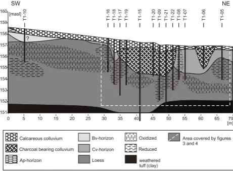
Figure 3. Cross section of reconstructed soil layers of a slope in the Pleiser Hügelland near Bonn (Löwner et al., 2005)
Storage capacity in the form of colluvial footslopes is common in many landscapes. Bork (1988) describes basal colluvium deposits in many parts of central and northern Germany, typically formed as a result of diffuse soil erosion. Temporary storage of sediment on slopes is also common, but would perhaps not generally be expected on such a short slope with an undercutting channel, such as in this case.
Löwner et al. (2005) reconstructed a colluvial fill on the middle slope of a loess covered area of the Pleiser Hügelland near Bonn, Germany.
Figure 3 depicts a cross section of its reconstructed soil layers. The volumes and shape of both the material eroded from the slope and the colluvial body has been reconstructed with the aid of geoelectrical surveys and a series of soil augerings.
The underbed consists of Oligocene trachyt tephras (approx. 23 m years old) covered by an Aeolian sediment called loess that is more than 10 thousand years old (Sieberts, 1983). This layer is upwardly bounded by first, a Bv-horizon that reflects centuries of soil building processes and, second, by two charcoal-bearing colluvial bodies that fill up an erosional gully. The top layer consists of calcareous material mobilised and accumulated by sheet erosion. Since loess is quite calcareous, origin of this material is a severely eroded area of the top and middle slope, i.e. the origin material is loess.
Based on optically stimulated luminescence ages (Lang and Wagner, 1996) of approx. 1250 years before present (b.p.) at the bottom of the gully provided by Preston (2001), genesis of the hillslope was reconstructed as follows (Löwner, 2000):
Erosion of the decalcified top soil of the slope and cutting a linear erosional feature, i.e. a gully by sheet erosion and subsequent linear erosion processes. Since luminescence ages date the last exposure of minerals to the daylight, filling of the gully is assumed to start 1250 b.p.
Padding the gully after 1250 b.p. with material eroded at the upper slope. Since the colluvial fill contains char coal, slash and burn activities are identified as the concomitant circumstance of these era.
Further sheet erosion at the top slope and the mid slope and accumulation of material at the slope foot. Since this material differs from the first colluvium a different system state can be assumed. Unfortunately, no more dating could be performed.
Today’s soil layer depth on the eroded slope was compared with maximum depth that is possible under give climatic conditions. Results clearly indicate a material export from the slope system
to the receiving stream. Löwner et al. (2005) calculated a sediment delivery ratio, i.e. the proportion of sediment yield to total eroded material from within a catchment (Cooke and Doornkamp, 1990), of 88%. Thus, next to accumulation of material on the food slope, a reasonable amount of material left the slope system.
The example shows that currently visible landforms such as slopes are normally the result of a complex genesis. Next to geometry, topological relations, material properties and processes that cut and build landforms or parts of them are of great significance. They can be viewed as an edge connecting two or more parts of a landform during a certain period of time.
4. PROPOSED MODEL
In this section, we propose a novel framework for the representation of 3D landforms that overcomes the limitations of existing practices in the field of landform interpretation. The entire data model will be given in UML. Classes, attributes and rules are written in italic.
We define a Landform as abstraction of the collection of all topographic real-world objects being relevant landform structures such as sandstone, near-surface underground, or surface-of-sliding. The conceptual modelling of a landform and its components employs the ISO 19100 series of geographic information standards for the modelling of geographic features issued by ISO/TC 211. According to the General Feature Model (GFM) specified in ISO 19109 (ISO/TC 211, 2008), geographic features are defined as abstractions of real world objects. The GFM is a metamodel that introduces general concepts for the classification of geographic features and their relations as well as the modelling of spatial and non-spatial attributes and operations. Object oriented modelling principles can be applied in order to create specialization and aggregation hierarchies.
4.1 Landform, LandformLayer and LandformState
A Landform is the basic unit for modelling 4D landforms within the proposed framework. Landform maps topographic landform components onto respective GFM feature types. Each Landform is an aggregation of 3D LandformLayer where each layer represents a 3D state or 3D epoche within the period of the landform (rf. Figure 4). LandformLayer is an aggregation of Abstract_Structure and StructureBoundary associated with LandformState that represents the dual representation of a LandformLayer. A main concept of our modelling approach is the dual representation of a LandformLayer so that each landform component can be represented both, by its 3D topography and by means of a complementary graph structure called LandformState. The dual representation addresses the need for both types of representation. The LandformLayer utilizes the Poincaré Duality in order to simplify the complex spatial relationships between 3D objects by a combinatorial topological network model.
ISPRS Annals of the Photogrammetry, Remote Sensing and Spatial Information Sciences,
«
Figure 4. UML class diagram of the LandformCore model
Solid 3D objects in primal space, e.g., horizons of a landform, are mapped to nodes (0D) in dual space. The common 2D face (StructureBoundary) shared by two solid objects is transformed into an edge (1D) linking two nodes in dual space. Thus, edges of the dual graph represent adjacency relationships in primal space. A formal definition of the Poincaré Duality is given by Munkres (1984). Thus, each LandformState represents a subgraph of the whole landform graph structure on the one hand side and on the other hand side a period in time of landform genesis.
Furthermore, modelling of 3D topography is realized in compliance with ISO 19109 as spatial aspect of Abstract_Structure and StructureBoundary. The value domain for spatial attributes is defined by the Spatial Schema specified in ISO 19107 (ISO/TC 211, 2008) which allows for describing the geometry of a LandformLayer (see Figure 4) in up to three dimensions. In addition to its 3D geospatial representation, each LandformLayer is mapped by LandformState onto a separate graph structure representing its structural and topological aspects. The proposed LandformState explicitly allows for a graph-based representation of each LandformLayer. The resulting graph structure follows the general principles of graph theory (Diestel, 2005). Abstract_Structure as basic unit for modelling landform structures allows for modelling thematic properties as well as the definition of taxonomies and parts of landform components in primal space. As Figure 5 indicates a structure can be represented according to the ISO 19107 in topological and geometrical space. In primal space, (upper part of the figure) topology is induced by the corresponding disjoint 3D geometry in Euclidean space. By applying a duality transformation based on Poincaré duality, the 3D cells in primal topology space are mapped to nodes (0D) in dual space.
«
Figure 5. Simultaneous spatial and topological representation of landforms
The topological adjacency relationships between 3D AbstractStructure (StructureBoundary, i.e. a shared face) are transformed to
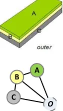
O C
B A
Figure 6. Simple example representing a landform in primal and dual space
DualStructureRelation (1D-edges) linking pairs of DualStructure (nodes) in dual space (see Figure 6). The resulting dual graph represents a Node-Relation-Structure (NRS) as proposed by (Lee and Zlatanova, 2008). Besides the topological relationships the StructureBoundary represents the common 2D face shared by two adjacent solids, e.g. the change of soil within the landform. Equal to Becker et al. (2008; 2009) an unknown or not needed boundary to adjacent structures can be represented in primal space as a shared Boundary with the outer environment – outer.
In dual space a DualStructureRelation is integrated into the overall graph structure (cf. Figure 5).
ISPRS Annals of the Photogrammetry, Remote Sensing and Spatial Information Sciences,
LandformState and its parts DualStructure, and DualStructureRelation represent the topology as dual graph based on the NRS model and is derived from topology in primal space by applying a Poincaré duality transformation. Such graph structure represents the topological relation of the landform to a specific point in (earth-) time. Thus it can be understood as a part of the landform genesis as depicted in section 3.
4.2 Abstract_GeoProcess as indicator of genesis
As illustrated before, the Node-Relation-Structure (NRS) of each LandformLayer constitutes a graph. The nodes represent the duality of a structure of a landform and correspond to horizons with volumetric extent in primal space while the edges represent the topological relations between adjacent horizons. They correspond to adjacency relations between the cells in primal space within the same period in (earth-) time.
If we presume that each layer is based upon a disjoint partitioning of (Euclidean) space, a state of genesis can only belong to one cell at a time and thus always only one epoch can be modelled. Since we have different landform layers with different topological representations, each layer contains such a landform state. The genesis of landforms is given by the interlinkage of corresponding dual structures. Corresponding means the resulting horizons of a following epoche of the landform afterwards a geological process.
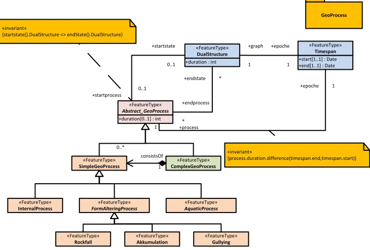
Geoprocesses are expressed by additional edges between the nodes of different layers. These edges are called Abstract_Geoprocess edges. The overall structure then constitutes a multilayer graph, where all the nodes from all N layers are included but are separated into N partitions of time which are connected by Abstract_GeoProcesses, see Figure 7. Once a geoprocess ends a new state in genesis is reached and thus a new LandformLayer has to be modeled. It is not permitted to run an Abstract_Geoprocess over several eras (LandformStates). Thus, an Abstract_Geoprocess must be reduplicated in a LandformLayer when another one ends. Therefor semantic sustainability can be ensured. It is up to the experience and knowledge of the modeler how detailed and complex a graph structure could be. However, a more detailed one should be give better understanding of the genesis of the respective landform.
An Abstract_GeoProcess is a generalisation of ComplexGeoprocess and SimpleGeoProcess. ComplexGeoprocess aggregate Abstract_Geoprocess-Features which build a functional and processoral unit such as the erosion of material by water, transportation of material and the subsequently accumulation of material on another site can be represented. Thus, they include further geoprocess entities such as AquaticProcess, InternalProcess, or FormAlteringProcess’s. A SimpleGeoProcess must not contain other process entities since it represents processes involving only one process force, one material and results in one process direction, ie. either erosion, transportation or accumulation.
Figure 7. Abstract_GeoProcess as connection between LandformStates
Using the Abstract_GeoProcess edge enables the mapping of the whole landform genesis onto a unique graph structure. Such a graph structure allows for simulation, analysis and comparison of landforms. The geomorphological example in the following section will give a more detailed vision of the proposed model and the benefits of application in the field of geosciences.
4.3 Modelling rules
Modelling rules amend a formal data model to enable semantic and topological integrity. Here we call for two essential requirements when modelling landforms using the proposed framework:
1. As soon as only one of the participating GeoProcess of the represented system ends or changes, a new LandformState has to be modeled. As a consequence, Abstract_GeoProcess and its children that continue more
GeoProcess
+duration : int «FeatureType»
DualStructure
+duration[0..1] : int «FeatureType»
Abstract_GeoProcess
+startprocess 0..1
+startstate
0..1
+endprocess
*
+endstate * «invariant»
{startstate().DualStructure <> endState().DualStructure}
+start[1..1] : Date +end[1..1] : Date
«FeatureType» Timespan +graph
1
+epoche
1
+process 1
+epoche 1
«FeatureType» SimpleGeoProcess
«FeatureType» ComplexGeoProcess
«FeatureType» InternalProcess
«FeatureType»
FormAlteringProcess
«FeatureType» Rockfall
«FeatureType» Akkumulation
«FeatureType» Gullying «FeatureType»
AquaticProcess
1 0..*
consistsOf «invariant»{process.duration.difference(timespan.end,timespan.start)}
ISPRS Annals of the Photogrammetry, Remote Sensing and Spatial Information Sciences,
than one LandformState without any change have to be reduplicated. That must be accepted to keep consistent semantic and topological composition.
2. If at least one boundary of a DualStructure is unknown, a DualStructureRelation to the outer has to be modeled. That is to fulfill the 1 to 1 multiplicity depicted in the UML diagram in Figure 4 and Figure 5.
The first of these modelling rules ensures a semantic and topological integrity. If an ending Abstract_GeoProcess would not cause the initialization of a new LandformState, time-dependency of a Abstract_GeoProcess would be questionable. On the other hand, introducing a new LandformState every time a represented process ends or changes can be viewed as a Level of Detail concept. The more is known about the genesis of a landform, the more instances of LandformStates, i.e. more time slices of a landform can be reconstructed.
5. APPLICATION ONTO A 4D-GEOMORPHOLOGICAL EXAMPLE
Here we apply the proposed model to a loess covered slope similar to the example outlined in section 3 and its genesis at four points in time (t0 – t3). We do this in a descriptive way without any exact rules for database implementation. The goal is to show that and how the model presented in section 4 is able to support representation of first, topological relations between structure elements of a landform, and second, the documentation of their changes, i.e. the temporal aspects of landform development.
The Landform and its constitutive LandformLayers are depicted as block models, implying geometry that can be represented using associated geometry classes. Because the main focus of attention is the representation of change within a graph structure, geometry associated with the Landform is not considered any further.
DualStructures of the LandformState at one time are represented as nodes and connected DualStructureRelations drawn by solid lines. These reflect direct topological relations of the DualStructures of one LandformState. Note the outer node that reflects the unknown landforms bounding the landform under consideration.
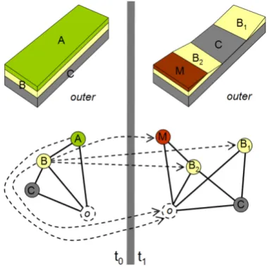
Figure 8. Representation of a landform by LandFormState at t0 and t1 and the change between these two points in time by Abstract_GeoProcesses (dashed arrows)
Changes from one time state to another by Abstract_GeoProcesses are depicted as directed dashed lines. As outlined in section 4, this class represents the upper class of different processes that also represent type of process, time span and rate.
The slope in its first state at t0 is composed out of three slope layers A, B, and C (
Figure 8). This is a typical situation of a loess slope under forest. Thus, the LandformState consists of four nodes, the three DualStructures that represent the three LandformLayers and the outer (o). There are five DualStructureRelations, A―B, B―C, A―o, B―o, and C―o. In general the outer represents the surrounding space and therefor other Landforms and LandformLayers which are either not known at that moment or of no interest to the researcher.
At a given moment, the whole system is disturbed e.g. by logging the forest and exposing the highly erodible soil to erosion by water for a certain period of time, e.g. hundreds of years. These processes result in the depicted slope in t1. The A-horizon is entirely eroded, the B-A-horizon is cut into two distinct soil layers and some of the material is accumulated at the slope foot due to decreasing slope angle and therefor decreasing flow velocity and transport capacity of water. The LandformState graph of t1 is given by seven DualStructureRelations B1―C, B2―C, M―B2, B1―o, B2―o, C―o, and M―o.
The Abstract_GeoProcesses causing the change of geometry and topological relations are depicted in dashed arrows representing directed edges between the old DualStructure of a Landform and the new one. With respect to stated modelling rules in section 4.3 all of them start at t0 and end in t1. From t0 to t1 we can identify five Abstract_GeoProcesses or children of it, respectively:
At0→ ot1, (erosion): All the material of the A-horizon (i.e. a Structure) is eroded and transported out of the system to a place elsewhere, the outer. Normally this material will be transported by fluvial activity.
Bt0→ B1t1 and Bt0→ B2t1 (ersosion): Bt0 is eroded so that it is divided into two distinct LandformLayers. Nevertheless, material properties of Bt0, B1t1 and B2t1 stay identically.
Bt0 → Mt1 (erosion and accumulation): Some of the material eroded from Bt0 is accumulated as a migration horizon because of decreasing transportation capacity of water at the slope foot.
Bt0 → ot1 (erosion): The most material eroded from LandformLayer B is transported out of the system.
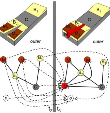
The slope in its third state at t2 again appears modified (Figure 9). A gully was formed during state t1 and t2 that cut into M, B2 and C. M was split in two disjoint Structures. That could be the result of a heavy storm event on the slope while plant cover was absent in spring. The LandformState of t2 is represented by nine DualStructureRelations. These are B1―C, B2―C, M1―B2, M2―B2 and five DualStructureRelations of all DualStructures with the outer that are not depicted here for the sake of clarity. Five Abstract_GeoProcesses that cause the change of state from t1 to t2 can be identified and represented as directed edges within our proposed framework:
Mt1→ M1t2 (erosion): Mt1 is eroded by linear erosion so that it is divided into two distinct LandformLayers, M1t2 and M2t2.
Mt1→ M2t2 (erosion): dito.
Mt1→ ot2 (erosion): The eroded material is not redeposited within the slope system but gone elsewhere to the outer.
ISPRS Annals of the Photogrammetry, Remote Sensing and Spatial Information Sciences,
B2t1→ ot2 (erosion): The same accounts for B2t1.
Ct1→ ot2 (erosion): The same accounts for Ct1.
Figure 9. Representation of a landform by LandFormState at t1 and t2 and the change between these two points in time by Abstract_GeoProcesses (dashed arrows). DualStructure-Relations to the outer at t1 have not been included for t2.
In its fourth stage at t3 the relief on the slope is decreased by sheet erosion and accumulation processes (Figure 10). The gully is filled with material coming from the upslope landforms and from the outer. The LandformState graph of t3 is given by 14 DualStructureRelations. These are B1―C, B2―C, M1―B2, M2―B2, B2―M3, M1―M3, M2―M3, C―M3 and six DualStructureRelations of the DualStructures with the outer. Ten _Geoprocesses can be identified and represented as directed edges between t2 and t3:
Figure 10. Representation of a landform by LandFormState at t0 and t1 and the change between these two points in time by Abstract_Geoprocesses (dashed arrows). DualStructure-Relations to the outer has not been included.
B1t2→ M3t3 (erosion, fall, accumulation): Material may be washed into the gully and fill it or just break down from the wall of the gully.
B1t2→ ot3 (erosion)
B2t2→ M3t3 (erosion, fall, accumulation)
B2t2→ ot3 (erosion)
M1t2→ M3t3 (erosion, accumulation)
M1t2→ ot3 (erosion)
M2t2→ M3t3 (erosion, accumulation)
M2t2→ ot3 (erosion)
ot3 → M3t3 (erosion and accumulation): If allochthonous material, i.e. material coming from outside the system under research, can be found in the colluvial body it must come from the outer. This is a valid representation, because the outer is nothing but a DualStructure.
This exemplification shows that a complex genesis of a realistic example slope can be represented within the proposed framework. Thus, the meaningfulness of that approach could be demonstrated. Even though the class model in section 4 is still in a preliminary stage, it is a promising start to represent the temporal aspects of landform development. Choosing a graph approach, this change can be represented even if no exact geometry is available.
6. CONCLUSION AND OUTLOOK
We presented a novel framework for the representation of the temporal aspects of landform development as a result of natural processes that overcomes the limitations of existing practices in the field of landform representation. The proposed data model represents the 3D topography, 3D topology and the geological genesis of landforms. Concerning the previously existing models, the suggested model can be considered as a superset with regard to model expressivity. This will improve the possibilities to exchange or link data between different application fields. Applying the Poincaré Duality simplifies the complex spatial relationships between 3D objects and enables the modelling of geological processes over time (4D). Hence, single landform layers are represented as nodes, i.e. the DualStructures and the neighbourhood of these layers are represented as edges, i.e. the DualStructureRelations. Finally, a DualStructureState represents a whole landform of stable conditions over a period of time. All dual representations may be associated with geometric and semantic representations if available.
The change of landforms is characterized by processes such as eroding, transporting, and accumulating material from one landform or a part of it to another. These geological processes can be considered to be constant over a period of time. They are represented as edges, i.e. Abstract_GeoProcesses, connecting landform layers of different time spans. Therefore, a semantic description of a process and its effects concerning the change of a landform can be obtained. This has not been modeled in detail, here.
We applied this model to a real landform reconstructed by geomorphologists with all the uncertainties that are common, when natural landforms and their genesis are investigated. The proposed framework allows for the representation of very detailed to a less detailed description of landforms. If more layers can be identified by the researcher, more nodes can be represented. This accounts for temporal resolution, also. The more processes or changes of rates of one process are identified, the more DualStructureStates may be represented. No requirements are made concerning the number of represented states. That avoids the definition of Level of Details and the related problems associated with it (rf. Löwner et al., 2013). To represent only a lower level of information, time slices may just be omitted.
ISPRS Annals of the Photogrammetry, Remote Sensing and Spatial Information Sciences,
A problem may arise applying the framework according to the ISO 19107. Since every geometric instance is allowed to have only one topological representation, no 3D topology can be represented within this framework next to the Poincaré Duality.
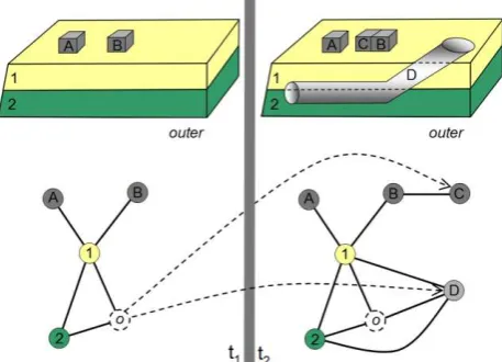
Figure 11. Change of a city by building activity. The state of a city between t1 and t2 changes by man-made processes.
Further work has to be done transferring the proposed framework to further application fields such as landslide monitoring, civil enginieering and urban development. An outlook is depicted in Figure 11. A more generic modelling approach enables the representation of change of built-up areas due to construction activity in combination with natural environment. Here, from state t1 to t2 the state of the city changes by the construction of a building and of a tunnel. All these constructions are topological related to the natural environment. Since the outer may be viewed in terms of actors, it has to be modelled in a different way than in the proposed framework, here.
7. REFERENCES
Adachi, Y., Forester, J., Hyvarinen, J., Karstila, K., Liebich, T., Wix, J. 2003. Industry Foundation Classes IFC2x Edition 2, International Alliance for Interoperability, http://www.iai-international.org (01 Aug. 2013).
Becker, T., Nagel, C., Kolbe, T. H., 2008. A Multilayered Space-Event Model for Navigation in Indoor Spaces. In: Lecture Notes in Geoinformation and Catrography: 3D Geo-Information Sciences, pp. 61-77.
Becker, T., Nagel, C., Kolbe, T. H., 2009. Supporting Contexts for Indoor Navigation using a Multilayered Space Model. In: Tenth International Conference on Mobile Data Management: Systems, Services and Middleware, IEEE Computer Soc.P.,U.S.
Bork, H.-R., (1988). Bodenerosion und Umwelt. Verlauf, Ursachen und Folgen der mittelalterlichen und neuzeitlichen Bodenerosion. Landschaftsgenese und Landschaftsökologie 13: 249 pp.
Bork, H.-R., Bork, H., Dalchow, C., Faust, B., Piorr, H. P., Schatz, T., 1998. Landschaftsentwicklung in Mitteleuropa, Stuttgart, 328 pp.
Caine, N., 1974. The geomorphic processes of the alpine environment. In: Ives, J. D., Barry, R. G., (eds.). Arctic and Alpine Environments, pp. 721-748.
Brunsden, D., 1996. Geomorphological events and landform change, Z. Geomorph., N.F. 40, pp273-288.
Brunsden, D., Kesel, R. H., 1973. The evolution of a Mississippi river bluff in historic time. Journal of Geology 81, pp. 576-597.
Cooke, R., Doornkamp, J. C., 1990. Geomorphology in environmental management, Oxford, 410 pp.
Dalrymple, J. B., Blong, R. J., Conacher, A. J., 1968. An hypothetical nine unit landsurface model, Z. Geomorph. N. F. 12, pp. 60-76.
Dikau, R., 1989. The application of a digital relief model to landform analysis in geomorphology. In: Raper, J. (ed.). Three dimensional applications in Geographic Information Systems, Taylor & Francis, London, pp. 51-77.
Dikau, R., 1996. Geomorphologische Reliefklassifikation und -analyse. Heidelberger Geographische Arbeiten, 104, 15-23.
Diestel, R., 2005. Graph theory. 3rd edition, Series on Graduate Texts in Mathematics 173, Berlin
Egenhofer, M. J., Herring, J. R., 1990. A mathematical framework for the definition of topological relations. Proceedings of the Fourth International Symposium on SDH, Zurich, Switzerland, pp. 803-813.
Emgård, K. L., Zlatanova, S., 2008a. Implementation alternatives for an integrated 3D information model. In: Van Oosterom, Zlatanova, Penninga&Fendel (Eds.). Advances in 3D Geoinformation Systems, Lecture Notes in Geoinformation and Cartography, Springer, Heidelberg, pp. 313-329.
Emgård, K. L., Zlatanova, S., 2008b. Design of an integrated 3D information model. In: Coors, V., Rumor, M., Fendel, E. M., Zlatanova, S., (Eds,). Urban and regional data management: UDMS annual 2007, pp. 143-156.
Govers, G., van Daele, K., Desmet, P. J. J., Poesen, P., Bunte, K., 1994. The role of tillage in soil redistribution on hill slopes. European Journal of Soil Science 45. pp. 469-478.
Govers, G. Quine, T. A., Desmet, P. J. J., Walling, D. E., 1996. The relative contribution of soil tillage and overland flow erosion to soil redistribution on agricultural land. Earth Surface Processes and Landforms 21. pp. 929- 946.
Gröger, G., Kolbe, T. H., Nagel, C., Häfele, K.H., 2012. OpenGIS® City Geography Markup Language (CityGML) Encoding Standard, Version 2.0.0, OGC 08-007r2.
ISO/TC 211,.2008. Geographic Information - Rules for application schema. ISO 19109: 2005, International Organization for Standardization (ISO).
Jones, C.B., 1989. Data structures for three-dimensional spatial. International Journal of Geographical Information 3:1, pp. 15-31.
Kugler, H., 1974. Das Georelief und seine kartographische Modellierung. Dissertation B, Martin-Luther-Universität Halle.
Lang, A., Wagner, G. A., 1996. Infrared stimulated luminescence dating of archaeosediments. Archaeometry 38, pp. 129-141.
ISPRS Annals of the Photogrammetry, Remote Sensing and Spatial Information Sciences,
Lee, J., 2004. 3D GIS for Geo-coding Human Activity in Micro-scale Urban Environments. In: M.J. Egenhofer, C. Freksa, and H.J. Miller (Eds.): GIScience 2004, LNCS 3234, pp. 162-178.
Lee, Y., Zlatanova, S., 2008. A 3D data model and topological analyses for emergency response in urban areas. Geospatial In: Zlatanova, S., Li, J. (eds). Information Technology for Emergency Response , Taylor & Francis Group, London, pp. 143-168.
Lindstrom, M., Nelson, W., Schumacher, T., Lemme, G., 1990. Soil movement by tillage as affected by slope. Soil and Tillage Research, 17 pp. 255–264.
Lindstrom, M., Nelson, W., Schumacher, T., 1992. Quantifying tillage erosion rates due to mouldboard ploughing. Soil and Tillage Research 24. pp. 243–255.
Löwner, M.-O. (2000): Geophysikalische und sedi-mentologische Untersuchungen zu Sedimentspeichern auf Gut Frankenforst. Unpublished diploma theses at the Department of Geography, University of Bonn, Germany, 141 S.
Löwner, M.-O., 2008. Towards a GML3-based application model for geomorphic Objects. In: Lee, J., Zlatanova, S. (Eds.), Proceedings of the 3rd International Workshop on 3D Geo-Information. Nov. 13.-14. 2008, University of Seoul, pp. 11-15.
Löwner, M.-O., 2010. New GML-based application schema for landforms, processes and their interaction. In: Otto, J.-C., Dikau, R. (Eds.): Landform - Structure, Evolution, Process Control. Lecture Notes in Earth Sciences 115, pp. 21-36.
Löwner, M.-O., 2013. On problems and benefits of 3D topology on under-specified geometries in geomorphology. In: Pouliot, J., Daniel, S., Hubert, F., Zamyadi, A. (Eds.). Progress and New Trends in 3D Geoinformation Sciences. Lecture Notes in Geoinformation and Cartography, pp. 155-170.
Löwner, M.-O., Benner, J., Gröger, G. & Häfele, K.-H., 2013. New Concepts for Structuring 3D City Models - an Extended Level of Detail Concept for CityGML Buildings. In: B. Murgante et al. (Eds.), ICCSA 2013, Part III, LNCS 7973, Springer, Heidelberg, pp. 466-480.
Löwner, M.-O., Preston, N. J., Dikau, R., 2005. Reconstruction of a colluvial body using geoelectrical resistivity. Z. Geomorph. N. F., 49(2) pp. 225-238.
Munkres, J. R., 1984: Elements of Algebraic Topology. Addison-Wesley, Menlo Park, CA
Pike,R., Dikau, R., 1995. Advances in Geomorphometry. Z. Geomorph., N.F., Suppl.-Bd. 101, Stuttgart.
Preston, N. J., 2001. Geomorphic Response to Environmental Change: the Imprint of Deforestation and Agricultural Land Use on the Contemporary, Landscape of the Pleiser Hügelland, Bonn, Germany. Phd thesis, Geographisches Institut der University of Bonn.
Requicha, A. A. G., 1980, Representation for rigid solids: Theory, methods and systems, ACM Computing Surveys, 12, 437 pp.
Sieberts, H., 1983. Neue sedimentologische Untersuchungs- ergebnisse von weichselzeitlichen äolischen Deckensedimenten
auf dem Niederrheinischen Höhenzug. Arbeiten zur Rheinischen Landeskunde 51, pp. 51-97.
Tegtmeier, W., Zlatanova, S., van Oosterom, P., Hack, H. R. G. K., 2009, Information management in civil engineering infrastructural development: with focus on geological and geotechnical information. In: Kolbe, T. H. Zhang, J., Zlatanova, S. (Eds.). Proceedings of the ISPRS workshop, vol. XXXVIII-3-4/C3 Commission III/4, IV/8 and IV/5, pp.1-6.
Welch, D. M., 1970. Substitution of space for time in a study of slope development. Journal of Geology 78, pp. 234-239.
Zlatanova, S., 2000, On 3D topological relationships, In: Proceedings of the 11th International Workshop on Database and Expert System Applications (DEXA 2000), 6-8 September, Greenwich, London, pp. 913-919.
ISPRS Annals of the Photogrammetry, Remote Sensing and Spatial Information Sciences,