UAV-MAPPING
–
A USER REPORT
W. Mayr
GERMATICS GmbH, Oskar-Frech-Str. 15, D-73614 Schorndorf – ([email protected])
Commission I, WG I/V
KEY WORDS: UAVs, Photogrammetry, Regulations, Sensor Orientation, Flight planning, Robotics
ABSTRACT:
This paper reports on first hand experiences in operating an unmanned airborne system (UAS) for mapping purposes in the environment of a mapping company. Recently, a multitude of activities in UAVs is visible, and there is growing interest in the commercial, industrial, and academic mapping user communities and not only in those. As an introduction, the major components of an UAS are identified. The paper focuses on a 1.1kg UAV which is integrated and gets applied on a day-to-day basis as part of an UAS in standard aerial imaging tasks for more than two years already. We present the unmanned airborne vehicle in some detail as well as the overall system components such as autopilot, ground station, flight mission planning and control, and first level image processing. The paper continues with reporting on experiences gained in setting up constraints such a system needs to fulfill. Further on, operational aspects with emphasis on unattended flight mission mode are presented. Various examples show the applicability of UAS in geospatial tasks, proofing that UAS are capable delivering reliably e.g. orthomosaics, digital surface models and more. Some remarks on achieved accuracies give an idea on obtainable qualities. A discussion about safety features puts some light on important matters when entering unmanned flying activities and rounds up this paper. Conclusions summarize the state of the art of an operational UAS from the point of the view of the author.
1. MOTIVATION
How can we open new business opportunities? This is a well known question not only in business. Apply new, advanced systems and offer services with them! This might be an answer. In terms of new tools miniaturization and integration of different technologies into new systems provide a very high probability of finding or creating new and advanced systems. Some time ago we got across unmanned airborne vehicles (UAV) and autonomous flight (Mayr, 2009). These initiated the idea of making UAV-based photo flights happen and maybe even do photogrammetric data processing with the images captured. We called this method resp. new technology UAV-Mapping. Soon, we were convinced that this sort of a robot will have the potential to open new business opportunities, and, in the long run, it might even complement the traditional flying approach with manned aircrafts.
UAV-Mapping, some prefer the term UAS-Mapping from unmanned aerial system to pronounce the system-character, enables us to operate an aerial imaging robot over smaller areas with the mimic of a traditional photo mission. Regarding data processing we aimed to recycle our photogrammetric expertise. Other interests were to fly below cloud coverage, to fly in many weather windows, to be highly agile, to minimize mobilization costs, to have a one-man operation, to reduce administrative hurdles as much as possible, to operate a very stable and advanced system resp. robot, and, of course, to offer attractive services. These and other considerations motivated us to seriously enter UAV-Mapping.
2. INTRODUCTION
One can do commercial projects with UAV-Mapping! There are limitations to it, but there are new opportunities as well. Many of us use car navigation systems and positioning services daily in our cars and smartphones, maybe without being aware of the level of technology integration we use. This level of integration, however, is it, what makes UAV-Mapping possible. In parallel to the technological progress, one can recognize an increasing demand on local, concurrent geospatial information. Unmanned airborne vehicles are equipped with special, miniaturized electronics and can execute in a fully autonomous manner an aerial survey flight covering smaller areas (Mayr, 2011).
Figure 1 PAMS UAV returning from a mission in NL
We apply the commercially available UAS-product PAMS (Personal Aerial Mapping System), see Figure 1, from SmartPlanes, Sweden. The system operates autonomously and delivers georeferenced aerial images, which one processes into International Archives of the Photogrammetry, Remote Sensing and Spatial Information Sciences, Volume XXXVIII-1/C22, 2011
orthomosaics, digital terrain or surface models (DTM or DSM) and other deliverables such as e.g. profiles, contours, or volumes. The following describes a system which automatically captures aerial images and processes them in a highly automated manner into the aforementioned geospatial image-based information.
3. SYSTEM DESCRIPTION
PAMS originates from the Swedish company SmartPlanes AB, Skellefteå, which develops, manufactures and distributes it. The system is based on a flying wing serving as airframe for the UAV. Such type of airplane has no tail, see Figures 1 and 2, and thus only two rudders, the so-called elevons. They combine and control elevator and aileron, meaning up – down and left – right movements of the airplane. Progress in control theory and electronics helped getting the complex steering control of a flying wing well manageable.
Figure 2 PAMS' SmartOne UAV with transport box, groundstation computer, accessories operation without serious failures. Its weight of less than 1.1kg when operating in air is intriguing. Other systems such as from Belgian GateWing or Swiss Sensefly are based on the flying complete the wing-ends. The airframe possesses surprising flying performance. Its wingspan is approximately 120 cm and houses the servos for the elevons, the antenna for its bi-directional data-modem, and the receiver for the manual remote control mode.
The third part of the flying wing is its fuselage. It puts over the joint wings and holds battery and camera, autopilot with GPS and IMU, and motor, see Figure 3. As single power source
serves an 11.1 V litium-polymer (LiPo) rechargeable battery. It enables SmartOne to fly with full load for approximately 45 min, of which, however, usually only 20 min to 30 min are required to complete one flight mission. The LiPo feeds one aft mounted motor and pushes the flying wing. This is as well a safety feature in case of impact.
The autopilot is the core of PAMS. It executes an a priori uploaded flight path completely autonomously and uses single frequency GPS for navigation and IMU for levelling support and attitude registration. Five devices connect to the autopilot. These are the two servos, the bi-directional modem, the receiver for manual remote control, and a USB port. The 10 Mpix camera connects via the USB port to the autopilot, which exposes location dependent. The autopilot communicates with the groundstation via a bi-directional modem. It downlinks status parameters such as attitude, GPS position, time and location of exposure, flying altitude above ground, voltage level of battery, speed over ground, and other useful control
parameters for the “grounded pilot”.
In emergencies or at any other time the pilot can take over immediately full manual control. This is an important safety feature and should be, in the opinion of the author, a mandatory UAS system property. PAMS has three flying modes. The autopilot exclusively controls the autonomous or “Auto2” flight mode. Manual control mode is possible at any time. The
semi-automatic mode, named “Auto1” is the 3rd mode, in which the pilot interactively controls speed and direction when needed, and otherwise the autopilot keeps the UAV levelled. This 3rd mode is the preferred one for starting and landing phases and makes it particularly easy for beginners.
PAMS is further equipped with a tracker system. In case of the sudden death of the battery, the autopilot will put the flying wing into fail safe mode. It shuts off the propeller, and directs the UAV into a spiral shaped curve gliding down slowly. The landing location might be out of sight. The tracker will point the pilot towards the UAV and thus helps finding it.
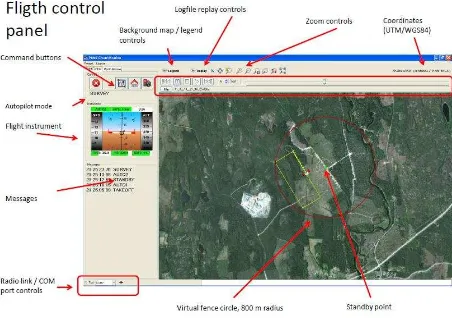
Figure 3 Groundstation display
The groundstation, see Figure 3, fulfils several tasks. It enables flight mission planning, flight preparation, flight mission control, and flight reporting. The user plans the photogrammetric block to be flown, either in office or on site. One can load a georeferenced background image, e.g. an orthophoto or a map, on top of which the dimensions of the block to be flown are digitized. The other parameter for the International Archives of the Photogrammetry, Remote Sensing and Spatial Information Sciences, Volume XXXVIII-1/C22, 2011
flight mission is either the flying height above ground level (AGL) or the desired ground sampling distance (GSD). The user enters either one of both parameters. Optionally, the user can modify the along track and across track overlaps. It defaults to an 80 / 80 overlap situation. This highly redundant overlap mimic is beneficial for later automated data processing and de-selecting potentially blurred images. Further, one can select the
geodetic coordinate system the user’s georeferenced
background information refers to.
During flight preparation the SmartOne UAV gets powered on. This causes the initial reading of its GPS location and constitutes the “home point” of the flight mission. Power on also initiates the communication between autopilot and groundstation via the bi-directional modem. Once established, the groundstation locates the UAV with a symbol over the georeferenced background image and displays the planned extent of the block. If all parameters are within valid range, they appear with green background. Otherwise yellow or red signalize warning or error conditions. This traffic light principle makes operating the groundstation easy.
Figure 4 Hand start to a flight mission in NL
The flight mission control monitors the execution of the photo performance of the UAV. The autopilot ought to keep the plane on a true circle while compensating for wind in real-time. A button push starts part 2, the actual photo mission. The autopilot takes the UAV up to photo-mission height over its home point and then steers the UAV to the entry point of the first strip of the block, where it starts block execution exposing location-based. After block completion, the 3rd part of the mission begins, returning to home point. It glides down and enters into parking position above its home point. The pilot checks once more airspace and wind conditions and initiates via groundstation the third phase, landing. This is mostly done in Auto1 mode, where the pilot points the UAV towards the landing spot, takes off speed and lets the autopilot keep level the plane and observes it gliding downwards.
After touch-down, see Figure 5, switching off the UAV terminates the flight mission. This initiates in the groundstation the generation of a flight report with GPS- and IMU-relevant information. This part of the groundstation software furthermore can import an existing report and re-play an animation of this flight mission. This way, the user can study the flight with all of its recorded data and as often as needed.
Figure 5 PAMS landed in snow – winter operations, too
Images get stored off-line on the SD-card in the camera. After loading them into the notebook the groundstation software can produce sort of a quick-mosaic. This visual control shows if full coverage is achieved and takes a few seconds to produce.
An optional software package, Aerial Mapper, takes GPS / IMU recordings, camera information, and aerial images, and generates within a few minutes kind of a mosaic. With the results of its executed automatic aerial triangulation Aerial Mapper projects all aerial images into a horizontal plane, forming an overall image which the author calls an airmosaic. This is not an orthomosaic, but comes close to it, in particular if the imaged, small surface has little elevation differences. Technically speaking, an airmosaic is a plane rectification consecutively executed on all aerial images of the block.
For higher level results, such as orthomosaic and DTM or DSM we use professional, particularly parameterized software. Regarding ground control points (GCP), we observed that their need is application dependent. For volumes no GCPs are needed. Often it is enough to use 2 to 4 GCP for georeferencing the orthomosaic only. Tests with signalized GCPs showed that one can achieve accuracies of half a pixel Two aspects have to be considered always. The most important one is Saftey first! Second, national regulations apply!
The author’s view is that the pilot must be able to be on command of a flight mission at any given time. Two mandatory consequences follow from this. First, the pilot must be able to take over manual flight control at any time, as mentioned above. Second, flight operations have to be done within visible range only. Other flying vehicles, birds or sudden climatic changes like rain or wind might require an immediate recognition and reaction resulting into a modification the flight path. PAMS International Archives of the Photogrammetry, Remote Sensing and Spatial Information Sciences, Volume XXXVIII-1/C22, 2011
allows different stages of reaction. One can abort the mission phase via the groundstation, and the autopilot immediately returns the UAV into parking position. If more interaction is required, the pilot can take over full manual control.
PAMS is designed for flight operations within visible range. To ensure this when in Auto2 mode a so-called virtual 3D-fence is implemented. This is a cylinder with e.g. 800 m radius around and a ceiling at 300 m above the home point. If the autopilot detects the UAV to go outside this 3D-fence it unconditionally aborts the flight mission and returns the UAV to parking position over its home point.
Another safety consideration is to use for flight missions only a new and fully charged battery. A typical flight mission of e.g. 900 m long strips and 350 m wide a block in 250 m AGL takes about 25 min to fly and generates some 280 images with a 7 Mpix camera. From 300 m AGL we obtain approximately 10 cm GSD and consequently 5 cm GSD from 150 m AGL. Largest blocks we have flown had the maximum strip length of 999 m and a block width of 550 m in 250 m AGL covering on ground an area of approximately 1.300 m x 730 m taking about 30 min to fly and producing some 310 aerial images.
As the SmartOne UAV is an airplane it requires a corridor for take-off and landing. Take-off is initiated with a hand-start, see Figure 4. Skilled pilots might get along with shorter or narrower corridors, e.g. a narrow forest road. Learning to fly PAMS can be accomplished in 2-3 days, which means, the person trained is able to bring up and land the UAV with support of Auto1 safely and to plan a flight mission. This level of flying skills does not indicate, you are a model airplane pilot, though.
Weather is the most important factor when flying. We did fly in temperatures above 35 Celsius as well as -10 Celsius. Wind influences flying mostly. Experienced pilots might fly at wind speeds of 15 m/sec and more. If possible we try to orient the block such that its strips are perpendicular to the wind direction. This might introduce big banking angles, but the high overlap of 80/80 ensures sufficient manifold overlap everywhere in the block. Also, one can fly at a close to constant speed in both directions, which is healthy for battery life, too. We experienced in a project close to the North Sea coast line extreme winds and had as low as 5 m/sec or 18 km/h upwind speed and more than 28 m/sec or 101 km/h downwind speed. Still, PAMS delivered perfectly fine images in the correct, pre-planned locations. In some of our projects we encountered, when flying close to the ridge of a steep hill, revolving air masses causing push-downs and up-lifts in the magnitude of up to +/- 10 m. The autopilot managed this wind condition pretty fine. In general, we are very satisfied with the performance of PAMS.
5. EXAMPLES
There are so many examples that it is hard to chose from. We flew different types of areas, a few of which we present here.
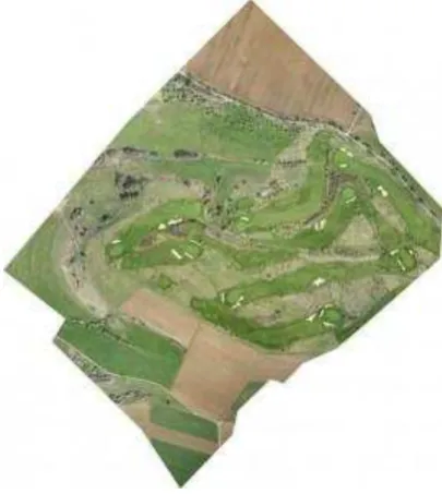
Example 1: Golf course operators are interested in presentation
and visualization possibilities as well as having a basis for planning. We flew various golf courses with resolutions down to 5 cm GSD and 150 m to 200 m AGL. Figure 6 shows an orthomosaic of parts of a golf course. This part of the green was flown in 1 block, covering on ground 840m x 680 m with
some 270 aerial images and in 250 m AGL. The derived DSM has a raster spacing of 40 cm.
Figure 6 Golf course Hechingen, Germany
Example 2 is a metro station in northern Germany. The train
operator contracted us to quickly produce an orthomosaic and DSM. Figure 7 shows the orthomosaic, and Figure 8 shows a section of the automatically generated DSM displaying the color-coded 3D-modelling of a road under-pass.
Figure 7 Orthomosaic of a metro station
This area was covered with four blocks and some 1190 aerial images from 150m AGL. Flying time was less than a day. The full resolution orthomosaic has 5 cm GSD and its DSM a raster spacing of 30 cm. Challenging was to fly over built up areas and finding appropriate spots for take-off and landing.
Figure 8 DSM section, road under-passing the train tracks
Example 3: Waste dump operators are interested in e.g.
volumes, contours, and profiles. This sample project consists of International Archives of the Photogrammetry, Remote Sensing and Spatial Information Sciences, Volume XXXVIII-1/C22, 2011
two blocks each in 150 m AGL totalling to 427 aerial images. Figure 9 shows the derived orthomosaic. Its original GSD is 5 cm. Figure 10 visualizes a perspective view of the DSM of this waste dump. Figure 12 displays the southwest part of the waste dump pile on which one clearly can see that it is now used for placing solar panels. The volume measured from the derived DSM is 9.2 million m3 which fits well to the recordings of the waste dump operator.
Figure 9 Orthomosaic of waste dump
Figure 10 Colorcoded DSM of waste dump
Figure 11 Southwest side of DSM with solar panels
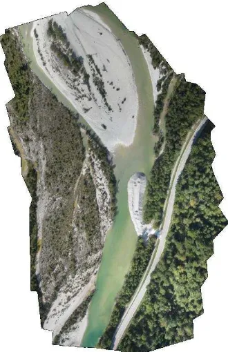
Example 4: In an environmental project a river authority in
Bavaria was interested to know the volume of a pile of coarse gravel which has been put into the river for re-naturalization purposes. The river shall distribute over time this pile of coarse gravel and thus stimulate the river to meander more, which in turn gives more habitats for fish. In order to control the volume put in and also the volume taken off by the river over time, this pile is flown periodically. Figure 12 shows the orthomosaic, original GSD 6 cm, of the area flown.
Figure 12 Orthomosaic of Alpine river environment
In the center of the image in Figure 13 one sees the pile of coarse gravel being of interest. 5.992 m3 were measured from the DSM which was close enough to the ordered 6.000 m3.
Figure 13 Perspective view of coarse gravel pile
Above environmental example was flown in 2 blocks in a narrow Alpine valley. Figure 14 shows the 2 flight missions, color-coded in red and yellow flight paths in about 180 m AGL. International Archives of the Photogrammetry, Remote Sensing and Spatial Information Sciences, Volume XXXVIII-1/C22, 2011
Figure 14 PAMS flight paths
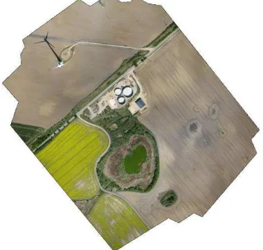
Example 5 deals with a project in the domain of renewable
energy. The operator of the world-first hybrid power-plant near Prenzlau, Germany, wanted a documentation of the construction progress. We flew this site and produced an orthomosaic, see Figure 15 and derived the according DSM, see Figure 16, with 25 cm raster spacing. This object required one block to fly in 250 m AGL in order to have a safe distance above the imaged wind mill. The GSD is at 8 cm. Since there was some wind of approximately 17 m/s the flight mission took approximately 25 min. The covered area extends 560 m by 470 m.
Figure 15 Hybrid Power-Plant, Prenzlau, Germany
Figure 16 Color-coded DSM of above orthomosaic
6. CONCLUSIONS AND OUTLOOK
UAV-Mapping entered the operational stage. Quite a number of projects, commercial ones as well as pilot or test projects, confirmed the applicability of this new, exciting technology. It remains to be expected that a number of systems will enrich the market place. Traditional products such as orthomosaics and DSMs are possible to be generated in sufficient quality and accuracy. We use off-the shelf software tools and parameterize them properly. UAV-Mapping opens the access to aerial mapping also for non specialists. There are many examples of applications, be it environmental applications, golf courses, forestry, agriculture, archaeology, police, emergency units, or disaster management, land slide monitoring, planning, and many more. Operational issues are very important and to be considered. With a flying vehicle one enters a new, operational dimension, in particular an unmanned and autonomously operating one and for a commercial purpose. National standards and regulations have to be obeyed. Airplane-based UAS-solutions seem to be suited better to mimic the traditional aerial mapping approach, while quadcopter- or in general rotary-wing-based UAS-solutions seem to fulfil other and evenly interesting and important applications. UAV-Mapping introduces the mapping community to new and thus far unknown applications. It is not competing but complementary to traditional aerial mapping operations.
7. REFERENCES
Mayr, W., 2011. Unmanned Aeria l Systems in Use for Mapping at Blom, Proceedings of 53rd Photogrammetric Week, Stuttgart, Germany, to be published
Mayr, W., 2009. PAMS – Personal Aerial Mapping System. White Paper, GERMATICS, www.germatics.com (accessed July-20, 2011)
GateWing: http://www.gatewing.com Germatics: http://www.germatics.com SenseFly: http://www.sensefly.com SmartPlanes: http://www.smartplanes.se