DEVELOPING PARAMETRIC BUILDING MODELS – THE GANDIS USE CASE
Wolfgang Thallera, Ulrich Krispela, Sven Havemanna, Ivan Redic, Andrea Redic, Dieter W. Fellnera,b a
Institute of Computer Graphics and Knowledge Visualization (CGV) Graz University of Technology, Inffeldgasse 16c/II, 8010 Graz, Austria
(w.thaller, u.krispel, s.havemann, d.fellner)@cgv.tugraz.at http://www.cgv.tugraz.at/ bFraunhofer IGD & Darmstadt University of Technology, Fraunhoferstrasse 5, 64283 Darmstadt, Germany
c
ORTLOS Space Engineering, Gleisdorfergasse 6, 8010 Graz, Austria. http://www.ortlos.org/
KEY WORDS:Geometry, Parameters, Graphics, Visualization, Software
ABSTRACT:
In the course of a project related to green building design, we have created a group of eight parametric building models that can be manipulated interactively with respect to dimensions, number of floors, and a few other parameters. We report on the commonalities and differences between the models and the abstractions that we were able to identify.
1 INTRODUCTION
The creation of building models is a tedious task. Sophisticated architectural software such as AutoCAD (Autodesk), ArchiCAD (Graphisoft) or Revit (Autodesk) provides architects with various tools for creating detailed plans and sections for the construction process. This software is typically used after the initial form find-ing process, i.e., when the buildfind-ing concept is clear, and function, stability, and style are defined (or, following Vitruvius, utilitas, firmitas, venustas). For the early design process all sorts of rapid modeling tools are used, most notably Maya or 3D Studio Max (Autodesk), or simple tools like SketchUp (Google), or Rhino (McNeel) for freeform architecture.
In this paper we present results from the GANDIS project, which attempts to close the gap between early design and construction-ready planning in a different way, namely usingprocedural build-ing templates. An important drawback of the conventional design process is that some implications of the initial design become ap-parent onlyafterconstruction planning. Theenergy footprintof a building, for instance, depends on the A/V ratio (surface to vol-ume), the glass proportion, the number of floors, but also of the wall insulation standard. So the requirement was to create an in-teractive planning tool that allows for computing characteristic key values from a set of prototypical parametric buildings. Even if the prototype buildings are only roughly similar to the building to be planned, the tool allows judging the impact of changes in the building on the energy footprint. This allows answering ques-tions such as: How compact should the building be, what happens if we create this overhang, and how expensive is it to compensate energy loss by better insulation on that wall, etc.
We consider parametric building templates to be useful for many applications other than energy design. The examples created in this case study are simple, but once the approach is clear, more
targeted and elaborate building models can be created using the same approach. The objective of this paper is to illustrate the pro-cess of developing parametric building models, in the hope that others can learn from it. We seek to provide anenabling tech-nologyfor interactively changeable complex procedural building templates.
The process starts from a set of example buildings provided by ar-chitects (Fig. 1). They span thedesign spacethat is to be param-eterized. To define this space unambiguously, however, required many discussions, e.g., on the parameter minima and maxima, or to clarify which special cases should be prevented to guarantee that the building created remains valid. The next step was to de-velop first simple buildings, and then to successively extend them to create more complex ones. This inductive process is marked by continuous refactoring in order to find a set of re-usable paramet-ric sub-constructions (doors, windows, floor plan processing). So our experience was that developing the first few models took most of the time, while later the toolset and thus, the design space, were powerful enough to create more elaborate models faster. The Of-ficeseries of templates was created from theResidentialseries merely by replacing the facade decoration function (see sec. 5.6).
2 RELATED WORK
Figure 1: Exploring the design space of the “residential” build-ings: static reference models created with conventional modeling software (Google SketchUp) served as guideline for abstraction. or RhinoScript (Robert McNeel & Associates, 2011) etc. We also use a programming language (GML), but it was primarily de-signed as an efficient shape description language, and not as an add-on to a graphical 3D editor. Grasshopper, a Rhino plugin, is a graphical dataflow editor that allows designers to explore algo-rithmic shapes without programming. Compared with program-ming, this approach limits the expressiveness with respect to pos-sible abstractions. In our approach, to find good abstractions is the goal.
Only very few approaches can be found in the scientific litera-ture. Chevrier et al. use parametric models to reduce the time for reconstructing heritage monuments (Chevrier et al., 2010). They created a Maya extension for parametric architectural elements. Users can select from a range of predefined parametric models, and after giving an initial estimate, the parameters can be adjusted using measurements from point clouds.
Finkenzeller (Finkenzeller, 2008) separates the coarse structure of a building from its appearance, which can be chosen from a given set of styles. The method uses annotated floor plans to de-fine the coarse outline. All information is stored in a graph struc-ture, together with basic architectural information, the locations of walls and balconies etc. The system can generate high-quality models with an appealing level of detail. However, the drawback is that Finkenzeller postulates a certain systematic of a building. Our approach is more generic and allows to structure buildings in different ways. In this sense, we see it more as a research tool for finding and developing good building structures.
A procedural modeling technique that recently received much at-tention areshape grammars. They were originally introduced by (Stiny and Gips, 1972), but only much later the grammar lan-guageCGA Shapefrom (Wonka et al., 2003, M¨uller et al., 2006) was developed into a commercial tool, the CityEngine from Pro-cedural Inc. We have also incorporated this split grammar ap-proach (Hohmann et al., 2010), but we found it insufficient to cover the whole design space we needed for GANDIS.
3 THE BUILDINGS & THEIR PARAMETERS
Designing an energy-efficient building is not just a question of the right insulation; the shape and orientation of a building are just as important. GANDIS provides aniPhone appthat allows users to interactively explore the impact of decisions made early in the design process on the energy footprint of a building. The user can choose betweenresidentialandofficebuilding and picks a basic
(a) (b) (c) (d)
Figure 2: In the GANDIS project buildings are grouped into sets with similar shape. The following basic shapes are used: rectan-gular 2(a), L-shaped 2(b), atrium 2(c) and a freeform 2(d) type.
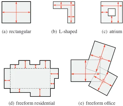
(a) rectangular (b) L-shaped (c) atrium
(d) freeform residential (e) freeform office
Figure 3: The first task was the definition of high level parame-ters (red) for each building shape.
shape for the floor plan (cf. Fig. 2). The building dimensions can be manipulated interactively while the GANDIS software contin-uously updates estimates of the energy efficiency.
There are two parametric models for each of the four basic shapes (cf. Fig. 2). The first three basic shapes,rectangular,L-shaped andatrium, are intended to approximate the more accurate mod-els that will be created later in the design process. The fourth “shape” is calledfree-formand is intended not as a stand-in for any specific building but rather as an example that the user can manipulate in order to learn more about energy efficiency. In the beginning, we had to assess the variability of the buildings. For this, the architects in our team modeled a static instance of each building type using Google SketchUp (cf. Fig. 1). These reference models provided a helpful guideline in the discussion that led to the abstraction of the buildings. The exact set of pa-rameters varies between the different models. Common to all the models is the “number of floors” parameter; the rectangular buildings have length and width parameters, while the other types require more parameters to define their shape (cf. Fig. 3). Ad-ditionally, the residential building models allow a choice of three different roof shapes.
4 THE TOOLSET
This section describes the main tools and technologies that were combined to create the full range of parametric GANDIS models. 4.1 GML
(a) (b)
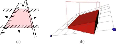
Figure 4: A solid convex region in 3D space is the intersection of halfspaces (oriented planes). Each plane divides space into unbounded interior and exterior. (a) The solid is the intersection of all interiors. (b) With this plane based representation, a part of a cube can be clipped away simply by adding another halfspace. data, in which case it is put on a stack, or a processing instruction, anoperator. Operators can use theoperand stackfor popping in-put parameters and pushing their results. However, the real work is done through side effects, by manipulating internal states and data structures. In GML, this might be a mesh data structure to which a vertex or a face is added. In PostScript, where the con-cept originates from, this is the bitmap of the page to be printed. 4.2 Shape representation: convex polyhedra
Shapes are represented in our system by solidconvex polyhedra (CPs). A CP is defined by the intersection of a finite number of halfspaces, i.e., oriented planes. Each plane is defined using three 3D points, the point orientation permits to distinguishabovefrom belowand thus, interior from exterior. – A more intuitive way to think about CPs is to imagine a piece of cheese from which parts are cut away using a knife. The main advantage of CPs is that they can besplitsimply byaddinganother plane (knife cut). To obtain the cut-away part, the plane is reversed. CPs are very robust; consistency is not an issue because if the halfspace intersection is empty, the CP simply vanishes.
CPs are so simple to use because the complexity of dealing with inconsistencies is encapsulated in the boundary computation. The vertex enumeration problem, which is dual to the convex hull problem (De Berg et al., 2000), is a special case ofConstructive Solid Geometry(CSG), also see (Hachenberger and Kettner, 2005). We have developed a robust and fast mesh clipping algorithm that can deal with the various special cases in a consistent way. How-ever, in principle any system that is able to evaluate convex poly-hedra can also be used, e.g., (CGAL, 2011).
Convex polyhedra are available in GML via a set of specialized operators and a few new token types. The following piece of GML code is sufficient to create the polyhedron in figure 4(b): 1 (−0.5,−0.5,−0.5) (0.5,0.5,0.5) cp−po−registerbox 2 dup
3 (0.9,0.9,0.032) (−0.9,−0.9,0.22) (0.9,−0.9,−0.44) 4 cp−pl−register
5 cp−po−addplane
6 / stdRed (0,0,0) 0 1 1cp−po−setproperties
Thecp-po-registerbox operator expects two 3D points on the stack, creates an axis-parallel box, and pushes on the stack a so-called CPticket. A ticket is a GML token that is used as reference to a piece of data, in this case of GML type “CP solid”. Thedup operator duplicates the topmost stack element.cp-pl-registerin line 4 creates a new plane (“CP plane”), and (cp-po-addplane) adds it to the existing polyhedron.cp-po-setpropertiesconsumes the duplicated box ticket and makes the polyhedron visible in red.
Figure 5: From convex polygon to convex polyhedron: The top and bottom planes are constructed from a given extrusion depth, and each polygon segment yields one side plane. In case the poly-gon is nonconvex, the solid is automatically “convexified”. As a more complicated example, the following code performs the prism construction shown in Fig. 5. In GML,!xdefines (pops) and:xretrieves (pushes) the value of named registerx.
1 % Function extrude−polygon
2 % Stack input : a convex polygon in 3D, a 3D direction vector 3 % Stack output : a convex polyhedron
4 usereg ! extrusion !poly 5
6 [ % choose three points to define bottom and top planes 7 : poly 0get
13 :poly3{ : extrusion add}map aload cp−pl−register 14
15 % bottom plane
16 :poly3 reverse aload cp−pl−register 17
23 :a : b :a : extrusion add cp−pl−register 24 }forx
25 ]
26 cp−po−register
4.3 Shape grammar
Shape grammars are a natural fit for many forms of architec-ture because grammars are well suited for describing hierarchical structures. Shape grammars are derived from formal grammars (Chomsky, 1956), which are part of formal language theory. This theory concerns itself with finite sequences of symbols called wordsand with — possibly infinite — sets of words called lan-guages. A formal grammar is a way of defining such a language. It consists of a setNof nonterminal symbols, a setΣof termi-nal symbols (thealphabet) and a setPof production rules. Each production rule describes a possible replacement of the symbols on its left-hand side by the symbols on its right-hand side. In a context-free grammar, the left-hand side is a single nonterminal symbol.
Grammar evaluation begins with a start symbolS ∈ N. Then rules are applied to replace nonterminal by other symbols, until a word consisting only of terminal symbols remains: The grammar has just generated a word. - A simple grammar looks like this:
S ::= AbA
A ::= cd
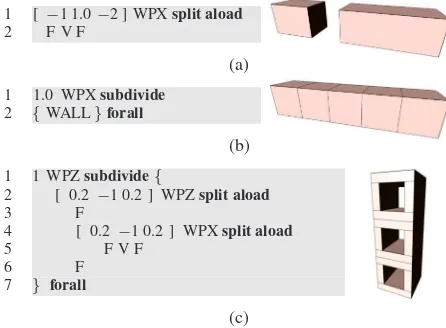
1 [ −1 1.0−2 ] WPXsplit aload 2 F V F
(a) 1 1.0 WPXsubdivide
2 {WALL}forall
(b) 1 1 WPZsubdivide{
2 [ 0.2−1 0.2 ] WPZsplit aload
3 F
4 [ 0.2 −1 0.2 ] WPXsplit aload
5 F V F
6 F
7 } forall
(c)
Figure 6: The split rule in (a) splits a volume into three symbols, F (“fill”), V (“void”), and F, along the horizontal axis, where the empty box should be one unit wide and the filled nonterminals should share the remaining space according to a proportion of
1 : 2. The subdivide rule (b) splits the box into equal parts with a minimum size of one unit. Both kinds of rules can be combined in interesting ways (c).
in any order) can yield the derivation sequencesS →AbA →
cdbA→cdbcdorS →AbA→Abcd→cdbcd, both generat-ing the same wordcdbcd.
The idea behind shape grammars is to operate on two- or three-dimensional shapes instead of one-three-dimensional symbol strings. In this case we use three-dimensional CPs labelled by symbols. The grammars we use aresplit grammars(Wonka et al., 2003): Each rule splits a CP carrying a specific label up into smaller polyhedra, covering the same volume and carrying other labels. We limit ourselves to deterministic grammars: For each non-terminal symbol, there is only one rule that applies to it. Conse-quently, a given grammar can only generate one word, i.e. evalu-ates to one 3D model for any given starting volume. Note, how-ever, that both the starting volume and the grammar itself can depend on parameters of the parametric model.
There are three kinds of production rules:
Terminal Rule Replace a nonterminal symbol by a single ter-minal symbol. Depending on the terter-minal symbol that is chosen, this will assign a material to the volume and make it visible, or make it entirely invisible.
Split Rule Splits the volume along one or more planes perpen-dicular to a given direction. The planes are distributed ac-cording to absolute and relative sizes given as part of the rule (cf. Fig. 6(a)).
Subdivide Rule Given a direction and a minimum size, splits the volume along planes planes perpendicular to that direc-tion into as many parts of equal size as possible (Fig. 6(b)).
We have embedded this formal shape grammar system into GML in order to use it for parametric modeling tasks. The grammar rules operate on the convex polyhedra described in the previ-ous section, a generalization of the commonly used rectangular boxes. The (nonterminal and terminal) symbols for the CP la-bels are not represented explicitly in the GML translation of a grammar; rather, we rely on the operand stack and on GML’s standard ability to define functions. Each rule name translates to a named function containing the GML code corresponding to
the rule. Note that with a one-to-one correspondence between nonterminal symbols and the rules that are applied to them, the nonterminals actually do not need to be labelled explicitly. Evaluating a GML shape grammar always starts with a CP at the top of the GML operand stack. Each rule is a GML function, or a sequence of tokens, that consumes one convex polyhedron from the top of the stack. While most rules become named GML func-tions, rules that are used only in one place can be directly placed into the calling function/rule. This rule “inlining” can make the textual description of a grammar much less verbose.
A split rule is implemented as a call to thesplitoperator (cf. Fig. 6(a)). It pops three arguments from the operand stack: the convex polyhedron to be split, a list of distances or proportions that de-termine the number and positions of the splitting planes, and the direction to split in. It returns an array of new convex polyhedra; further rules are applied to them by calling the respective GML functions. Likewise, a subdivide rule is implemented as a call to thesubdivideoperator (cf. Fig. 6(b)). It pops the polyhedron, the minimum size and the direction from the operand stack, and it returns an array of convex polyhedra. In the shape grammar for-malism, the same rule is applied to all polyhedra resulting from a subdivide, so this is done in aforallloop. A terminal rule is where the shape grammar formalism ends. It can be implemented by any code that does something with the resulting polyhedron. Most commonly, thecp-po-setpropertiesoperator is used to ei-ther assign a material to the polyhedron to make it visible, or to mark it as invisible.
5 DEVELOPING THE MODELS
There is more than one way to build any given parametric model. While creating the models, we were faced with several decisions; some of these had to be revised as we progressed from the simpler building types (rectangular, L-shaped) to the more complex ones (atrium, freeform).
5.1 Rectangular and L-Shaped Residential Buildings
Figure 7: Residential rectangular and L-shapes buildings. Once we felt we had sufficiently understood the architectural ideas that our parametric models had to capture, the first decision we faced was whether to rely on shape grammars right from the start, or whether to use more conventional methods, such as extrusion from a floor plan polygon.
(a) (b) (c)
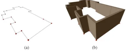
Figure 8: Floor slab construction. A simple polygon (a) is decomposed into convex parts that are extruded (b) to obtain the floor slab parts of the building (c).
(a) (b)
Figure 9: Wall construction. Given a simple polygon as outer boundary (a), one wall piece is constructed for each polygon seg-ment (b) by making use of the offset polygon.
is added. This should work in basically the same way for all building shapes.
The grammar formalism cannot deal well with non-convex shapes. It is not obvious how to define general, reusable rules that can be applied to a non-convex floor plan. It can often be easier to cal-culate a floor plan polygon from the building parameters directly (cf. Fig. 3). Polygons are versatile and can be turned into 3D shapes of floors and walls in a general way (cf. Figs. 8, 9).
Decision 1 We use polygonal floor plans and extrude them to get 3D representations of floor slabs and walls.
For every line segment of the floor polygon one wall segment is created, i.e., one convex polyhedron. This CP is then used as starting volume for a shape grammar. We have successfully em-ployed shape grammars for modeling fac¸ades (Krispel et al., 2010), which lead to the next design decision:
Decision 2 To model the building fac¸ades, we apply a shape gram-mar to each wall (on each storey).
An important decision is whether to construct the building floor by floor, or whether the side walls are extruded over all floors. The advantage of the latter approach is that the shape grammar can be applied to the entire fac¸ade, so that structures can cross floor boundaries. Still one floor slab needs to be created per storey, but that is feasible. However, despite this advantage a different design decision was taken:
Decision 3 All the buildings are created one storey at a time.
The reason for this decision is the freeform residential building, where different floors have different shapes. Another reason is that the fac¸ades of the GANDIS models are comparably sim-ple. Only one fac¸ade element is not strictly confined to a single floor (the large opening in Fig. 7, top left, middle building, upper floor). – The final remaining building block is the roof. A flat roof is basically just a floor slab. However, the other two roofs are more complicted, so due to the time constraints we decided:
Decision 4 The two non-trivial roof forms are constructed by a separate piece of GML code for each basic building shape.
We used hand-crafted convex decompositions of the building shapes in order to construct the convex polyhedra representing the roofs; this leads to eight different roof construction functions in the code (two roof forms for each of four building shapes). With more time and effort, they could be refactored and combined into a single function per roof type that works for all building shapes, rectan-gular, L-shaped and atrium. The residential freeform building, however, needs to be treated separately in any case because its roof has a different structure. The roofs on the simpler buildings follow the building shape, changing their slope in order to always reach the same height. In the freeform building the roof shape on “core” of the building remains fixed, and it extends outwards and upwards on the variable parts (cf. Fig. 3(d)).
5.2 Atrium
Figure 10: Residential atrium buildings.
The atrium shape posed a new challenge: its ground area is not a simple polygon but a polygon with a polygonal hole. One option is to extend the system to deal with this more complex shape directly, but there is also a more general alternative.
Decision 5 A floor polygon with holes is decomposed into a set of polygons without holes. The polygon sides are tagged to ac-count for constructing the walls, possibly a different set is used for creating floor slabs.
For constructing the walls of the atrium building, we use two (rectangular) wall polygons (cf. Fig. 11(a)); one for the outward-facing walls, one for the walls outward-facing the atrium. For constructing the floor slabs, the ring shape is split into two roughly L-shaped parts (cf. Fig. 11(b)).
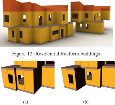
5.3 Freeform Residential
The freeform residential building uses a different shape for even-numbered and for odd-even-numbered floors. As we have already de-cided to construct each floor separately, this is no big problem.
(a) wall polygons (b) floor polygons
Figure 12: Residential freeform buildings.
(a) (b)
Figure 13: In the freeform residential buildings, the shape of a floor slab between storeys is influenced by both storeys. But we have to take into account that the shape of the floor slab that separates two storeys depends on the shapes of both the floor above it and the floor below it. If the lower floor extends fur-ther than the upper storey (cf. Fig. 13(a)), the slab that divides them is exposed as a roof; if the upper storey extend further (cf. Fig. 13(b)), the slab has to function as a floor. Therefore, the area of the dividing floor slab has to be the set-theoretic union of the areas of the lower and upper storey. In this particular case, we can trivially calculate the resulting polygon by always using the larger of the corresponding parameter values for the even and odd-numbered floors.
Decision 6 Separate polygons are generated for even and odd-numbered floors; the shape of the dividing floor slabs is calcu-lated from both sets of parameters.
5.4 Office Buildings
Figure 14: Office rectangular, L-shape and atrium buildings. For the simple shapes (rectangular, L-shaped, atrium), the office buildings are very similar to the corresponding residential build-ings. The only differences are that
1. the only available roof type is the flat roof,
2. the outer walls are lightweight curtain walls rather than solid walls with windows, and
3. the buildings have solid core at a fixed distance from the outer curtain walls.
To get curtain walls instead of solid walls with windows, all we have to do is to use a different grammar for the walls.
Decision 7 The core of the office buildings is modeled by adding an additional polygon (or two, for the atrium building) to the list of wall polygons. A different (trivial) grammar is applied to these additional walls.
5.5 Freeform Office
Figure 15: Office rectangular, L-shape and atrium buildings. The freeform office building consists of three intersecting rectan-gular parts, where each part has a different number of floors. If we model this building by constructing the individual floor poly-gons, we find that the top floor is a rectangle, the floor below it is the union of two rectangles, and all other floors are the union of three rectangles. Modeling the building in this way has one big disadvantage: the wall grammars are applied to walls of differ-ent lengths in differdiffer-ent storeys; therefore, corresponding fac¸ade elements in different storeys will not align properly. In order to account for this, we have to find a way to calculate the boundary of the combination of the floor parts, rather than treating the floor parts individually.
Decision 8 Rather than calculating the outlines of individual floors, we first construct three complete rectangular office buildings and then merge them together using CSG operations.
Constructive Solid Geometry, or CSG, is the term commonly used for set-theoretic operations on three-dimensional solid ob-jects, such as union, difference and intersection. By rendering all three rectangular parts of the building, we get a building with unwanted interior walls. For each of the three parts, we elim-inate the unwanted walls using two CSG difference operations; we “cut away” the walls that are inside the bounding boxes of the two other parts (cf. Fig. 16(a)).
Putting these parts together yields the desired result (cf. Fig. 16(b)). Note that the floor slabs and the building cores still have extra interior faces. Since a valid interior building core is not of interest in our project this was not resolved. If non-intersecting core geometry was required for further processing, the overlap-ping parts of the building core could also be properly merged using a CSG union operation. – Note that in particular such join operations pose a fundamental problem when using exclusively shape grammars. An extension tocontext-sensitiveshape gram-mars is not directly possible using the presented GML grammar approach, where grammar rules are realized as GML functions.
(a) (b)
Figure 16: Freeform office: (a) To avoid undesirable interior walls, the walls inside the other building parts are cut away using a CSG operation. (b) The result of the combination.
(a) (b) (c)
Figure 17: Three different fac¸ade styles 5.6 Construction of the walls
According to decision 2 the structure (or style) of each wall is defined by a shape grammar. Figure 17 shows some examples of the different wall styles that were required in our parametric model. As the wall grows longer, we will simply repeat the basic “tiles” to fill the wall. In the case of figure 17(c), there is an extra space in the middle of the wall (highlighted in blue), which should remain constant in width while the left and right parts are repeated.
The top-level rule of the wall grammar therefore uses the sub-divide operator for the first two cases; for the third case, a split rule is applied first, and subdivide is applied to the leftmost and rightmost parts. The grammar is applied to walls with different orientations; therefore, we will pass the direction of a wall as a parameter to the GML function defining the grammar.
The functionwall-cfor the toplevel nonterminal 17(c) looks as: 1 /wall−c{
The wordstile-aandtile-brefer to further nonterminals defined in separate functions;tile-ais the repeating part in the left half of the wall,tile-bis the part repeated on the right side. Both words take the wall direction as a parameter in addition to the convex polyhedron. Fortile-a, we first need the subdivide rule; then, still using the same direction, the tile is split up into parts for a window, a door, and for the walls in between:
1 / tile−a { 2 usereg ! dir 3
4 9.0 ; dir subdivide 5 {
In this codeTW(forterminalwall) is a terminal symbol, door-aandwindow-bare more nonterminals, and window-width-a andwindow-width-bare constants defined elsewhere. The rule fordoor-acan be defined as a split into an upper part, which is a wall, and a lower part, which uses the terminal symbolVfor void. The global constant WPZrefers to a split parallel to the world coordinate systemplanez= 0.
1 /door−a{
2 [ door−height−a−1 ] WPZsplit aloadTW V 3 }def
The definitions fortile-b,window-b, as well as for other types of windows, doors and walls (including the curtain wall used in the office buildings) are similar.
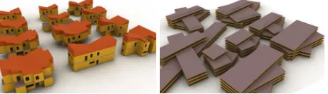
Figure 18: Populations of freeform buildings.
6 TAKING MEASUREMENTS
The main objective of the GANDIS project is to assess the en-ergy efficiency of a procedurally generated parametric building. In fact only a few key quantities are required for the approximate energy efficiency calculation. Some of them, such as the exterior area and the enclosed volume of the building, can be directly cal-culated from the parameters. It is much easier to multiply length, width and height of a box than to calculate the volume of a box-shaped building from the volumetric CP model. The most inter-esting challenge was to find out the exact amount of glass area on each of the fac¸ades of the building.
The area occupied by windows depends on the particular gram-mar used to define the fac¸ades. Different gramgram-mar rules behave differently when the wall length changes; therefore, we want to calculate the window areas just when building the wall geome-try, as this is possible then with little extra effort. The method of choice is to collect all “glass” terminals for each wall, and to cal-culate the total area facing in the wall direction. We already have a GML function that implements the “void” terminal symbol for expressing empty spaces in the shape grammar. Its code is simple as it usescp-po-setpropertiesto make the polyhedron invisible but for its outline:
1 /V{
2 / archwhite (0.3,0.3,0.3) 0 1 0 cp−po−setproperties 3 }def
This is the right place to add code to store a reference to the poly-hedron in a global array (more exactly, toappendit to the array): 1 /V{
2 usereg !polyhedron
3 WindowPolyhedra ;polyhedronappend 4
5 ;polyhedron / archwhite (0.3,0.3,0.3) 6 0 1 0cp−po−setproperties 7 }def
Whenever a window is created its 3D shape is stored in the global variableWindowPolyhedrafor future reference. The window areas must be calculated separately for each of the four points of the compass, so in fact four different wall arrays are needed. When applying the grammar to a wall theWindowPolyhedra variable must refer to the appropriate array. To obtain the actual window area the faces of the polyhedra facing to the respective direction are extracted, and their areas are summed up.
1 /glassAreaN 2 0.0
3 NorthWindowPolyhedra{
4 (0,1,0) getcpfacepoly polygonarea add 5 } forall
6 def
In the above code(0,1,0)is the direction of the positiveyaxis which points North in our coordinate system. The function getcp-facepolyexpects a polyhedron and a direction, and it returns, as a polygon, the face whose orientation matches most closely the given direction. An initial value of0.0is pushed first. For each north-facing window polyhedron, the area of the appropriate face is added to it. The result is stored in a variable namedglassAreaN. From a more abstract point of view, by adding the appropriate CPs to the wall direction array we have in fact labelled each “glass” terminal with a semantic attribute. After the model is finished we were then able to sum up the values calculated from the labeled terminals. Compared to calculating the area while the model is being constructed, this leads to a much cleaner over-all structure of the code. – We are currently also pursuing a more general and versatile solution that combines the attribute operator cp-po-setpropertieswith another operatorcp-po-getbyattrthat runs a query to obtain all CPs that are labeled with a particular at-tribute. In GML, the resulting object arrays can be further refined in a simple way using thefilteroperator that maps an array to a filtered array using an arbitrary filter function.
7 CONCLUSION AND FUTURE WORK
We have presented a technology for creating parametric build-ing templates. The goal of the GANDIS use case was to isolate the essential parameters of six specific parametric buildings fam-ilies. The parametrization leads to a reduction of the degrees of freedom that increases the efficiency of building design, since a smaller number of user interactions is required to obtain a build-ing compared to more general modelbuild-ing software.
The downside of this limitation is of course that the user cannot realize buildings outside of the given parametrization; i.e., the generality is impaired. This is compensated by the possibility to quickly realize other new parametric families using the GML framework developed in GANDIS, as witnessed by the two fam-ilies offreeformbuildings (residential and office), which follow a quite different systematic. Concerning the expressiveness of the framework we can observe that a large class of buildings can be realized despite some severe limitations, e.g.:
• No general roof algorithm, roofs are custom-tailored
• No interior walls or internal ground floor structure
• No Mezzanines, only one floor polygon per storey
• No vertical interior structures like elevators or stairways
• No vertical facade structures across storeys
These issues mark obvious areas for further generalization and future research. More important, however, will be the question whether the presented combination of GML, CPs with CSG, and shape grammars will be sufficient to cover also these extensions – or whether we need additional tools in the toolset.
All GANDIS models can be downloaded from the GML home-page www.generative-modeling.org. The energy bilance appli-cation for the Apple iPhone and iPad can be obtained from the AppStore under the name GANDIS.
ACKNOWLEDGEMENT
The authors gratefully acknowledge the generous support from the Austrian Research Promotion Agency (FFG) for the research projects GANDIS (Green Architectural Networked Digital Infor-mation System) and CITYFIT (High-Quality Urban Reconstruc-tions by Fitting Shape Grammars to Images and Derived Textured Point Clouds), grant number 815971/14472.
REFERENCES
Autodesk, 2011. Autodesk.
Chevrier, C., Charbonneau, N., Grussenmeyer, P. and Perrin, J.-P., 2010. Parametric documenting of built heritage: 3d virtual reconstruction of architectural details. International Journal of Architectural Computing 8(2), pp. 135 – 150.
Chomsky, N., 1956. Three models for the description of lan-guage. Information Theory, IRE Transactions on 2(3), pp. 113 –124.
De Berg, M., Van Kreveld, M., Overmars, M. and Schwarzkopf, O., 2000. Computational Geometry: Algorithms and Applica-tions. 2 edn, Springer.
Finkenzeller, D., 2008. Detailed building facades. Computer Graphics and Applications, IEEE 28(3), pp. 58 –66.
Google, 2011. SketchUp.
Hachenberger, P. and Kettner, L., 2005. Boolean operations on 3d selective nef complexes: optimized implementation and experi-ments. In: Proceedings of the 2005 ACM symposium on Solid and physical modeling, SPM ’05, ACM, New York, NY, USA, pp. 163–174.
Havemann, S., 2005. Generative Mesh Modeling. PhD thesis, Technical University Braunschweig.
Hohmann, B., Havemann, S., Krispel, U. and Fellner, D., 2010. A gml shape grammar for semantically enriched 3d building mod-els. Computers & Graphics 34(4), pp. 322 – 334. Procedural Methods in Computer Graphics; Illustrative Visualization. Krispel, U., Havemann, S. and Fellner, D. W., 2010. Famos - a vi-sual editor for hierachical volumetric modeling. In: Tagungsband 05. Kongress Multimediatechnik Wismar.
M¨uller, P., Wonka, P., Haegler, S., Ulmer, A. and Gool, L. V., 2006. Procedural modeling of buildings. In: ACM SIGGRAPH, Vol. 25, pp. 614 – 623.
Robert McNeel & Associates, 2011. Rhinoceros 3D.
Stiny, G. and Gips, J., 1972. Shape grammars and the generative specification of painting and sculpture. In: The Best Computer Papers of 1971, Auerbach, p. 125135.
CGAL, 2011. Computational Geometry Algorithms Library. http://www.cgal.org.