The effect of short time post-weld heat treatment on the fatigue
crack growth of 2205 duplex stainless steel welds
M.C. Young
a,1, L.W. Tsay
b,*, C.-S. Shin
c, S.L.I. Chan
daInstitute of Nuclear Energy Research, Division of Nuclear Fuels and Materials, Lungtan, Taoyuan 325, Taiwan, ROC bInstitute of Materials Engineering, National Taiwan Ocean University, Keelung 202, Taiwan, ROC
cDepartment of Mechanical Engineering, National Taiwan University, Taipei 106, Taiwan, ROC dInstitute of Materials Engineering, National Taiwan University, Taipei 106, Taiwan, ROC
Received 18 May 2006; received in revised form 11 January 2007; accepted 14 January 2007 Available online 24 January 2007
Abstract
The influence ofccontent and its morphology on the impact and fatigue crack growth behavior of 2205 duplex stainless steel (DSS) welds were studied in this work. Short time post-heating was able to effectively raise theccontent and the impact toughness of the weld. The variation in microstructures showed less influence on the fatigue crack growth rate (FCGR) of the steel plate and weld except in the lowDKregime. In contrast, residual welding stresses played a more significant affection on the FCGR of the DSS weld than microstruc-tural factors did. Plastic deformation induced martensitic transformation within a definitely thin layer was responsible for the difference in crack growth behavior between specimens in the lowDKrange. Coarse columnar structure was more likely to have tortuous crack path in comparison with the steel plate.
2007 Elsevier Ltd. All rights reserved.
Keywords: Duplex stainless steel; Laser welding; Fatigue crack growth rate; Charpy impact; Post-heat treatment
1. Introduction
DSSs (2205 duplex stainless steels) consist of compara-ble amounts of ferritic (a) and austenitic phases (c). This gives the DSS the superior strength and stress-corrosion cracking resistance of ferritic stainless steels, as well as good ductility and toughness of austenitic stainless steels
[1,2]. With these excellent properties, DSSs are used
increasingly in chemical industries such as pressure vessels, heat exchangers and line-pipes. DSSs are highly anisotropic because of the elongatedcphases embedded in theamatrix
[3]. As shown in the previous work[4], the anisotropy had
little influence on the fatigue crack growth rate (FCGR) of 2205 DSS in air.
Modern DSSs have good weldability and can be welded by conventional welding processes under careful control of heat input to ensure a correcta/cratio in the weld[5]. Pre-heat and post-weld Pre-heat treatments of a DSS weld are in general not recommended[5]. Laser welding process offers many advantages over conventional arc welding process. However, the low-energy processes accompanying with fast cooling rates produce welds with higheracontents, which is responsible for its poor impact toughness [6,7]. As a result, the electron beam and laser beam welding processes are not recommended for joining DSS welds[8].
To alter the unbalanceda/cratio in the fusion zone and HAZ of a DSS laser weld, laser surface treatment is used to restore the correct a/c ratio [9]. An addition of little amount of nickel powder[10]or assist-charging of nitrogen into the fusion zone during laser welding[11], may restore the correct a/c ratio. According to the literature survey,
0142-1123/$ - see front matter 2007 Elsevier Ltd. All rights reserved.
doi:10.1016/j.ijfatigue.2007.01.004
* Corresponding author. Tel.: +886 2 24622192x6417; fax: +886 2 24625324.
E-mail addresses:[email protected](L.W. Tsay),csshin@ntu. edu.tw (C.-S. Shin).
1 Fax: +886 3 4711409.
www.elsevier.com/locate/ijfatigue
International Journal of Fatigue 29 (2007) 2155–2162
little investigation has been carried out on the fatigue crack growth behavior of a DSS laser weld. In this study, short time post-weld heat treatments were performed after weld-ing to increase the c content in the fusion zone of a 2205 DSS weld. The effects of c content and its morphology on the impact and fatigue behavior of the DSS weld metal were evaluated. A magnetic technique and quantitative image analysis were used to determine the a/c ratios of the base plate and weld metal. Fatigue- and impact-tested specimens were examined by scanning electron microscopy (SEM) to identify fracture features, which were further cor-related with their properties accordingly.
2. Material and experimental procedures
The chemical composition of the 2205 DSS plate in weight percent was 21.1 Cr, 5.8 Ni, 2.7 Mo, 0.052 C, 1.42 Mn, 0.45 Si, 0.025 P, 0.022 S, 0.02 Cu, 0.165 N and balance Fe. Laser welding was performed on the as-received 5 mm thick DSS plate, using a Rofin-Sinar 5 KW CO2laser inte-grated with a computer-controlled working table. Laser welding parameters used in this work are listed inTable 1.
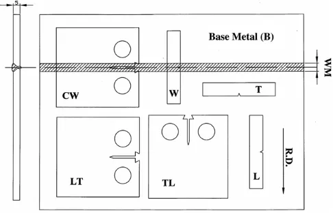
Fig. 1is the schematic diagram showing Charpy impact
and compact tension (CT) specimens sectioned from the laser-welded steel plate. The relative direction between crack growth and rolling direction (RD), named according to the ASTM E399 specification, is also indicated inFig. 1. Both fatigue crack growth and impact tests were carried out at room temperature in laboratory air. The fatigue crack growth tests were conducted on an MTS 810 model servo-hydraulic testing machine under a constant ampli-tude sinusoidal loading. Fatigue data were analyzed using the MTS 790.40 fatigue crack growth software. The load ratio was set at 0.1 throughout the test. The crack length was determined by a compliance method [12] and con-firmed by a traveling microscope at 30· magnification.
The welded CT specimen was designated as CW when the fatigue crack propagated along the weld metal, as shown inFig. 1. The stress intensity factor corresponding to the crack opening stress (Kop) was measured by compli-ance method using crack mouth clip gage. The degree of crack closure, U, was defined as the fraction of the load range for which the crack is open,U=DKeff/DK.
Austensite is known to be the stable phase in the temper-ature range from 900C to 1100C[1]. Therefore, a higha
content resulting from the high cooling rates in the as-welded (AW) DSS laser weld, or unbalanced phase ratio in the steel
plate, can be corrected by a proper heat treatment. In this work, post-heat treatment was carried out at 1050Cover
different periods of time from 15 to 60 min, followed by cool-ing in air to raise theccontent of the material. High soaking temperature not only restore the correcta/cratio but also help to release welding residual stresses. Welding residual stresses were determined by the modified hole-drilling strain gage method according to the specification of ASTM E837-92. Similar experimental procedures had been conducted in previous studies for the determination of residual stresses
[13,14]. The soaking time in minute was indicated as a
num-ber appending the specimen designation. For example, W15 or W60 indicates that the post-heating time was 15 or 60 min for the weld, respectively.
Due to the existence of fine and irregularain the fusion zone of the weld, thea/c ratio as determined using tradi-tional image analysis was hard to be conducted sometimes. A magnetic technique was used to assist the measurement of thea/cratio of the base plate and weld metal. The mag-netic technique, by means of the Ferrite scope, registered an average volume content of ferromagnetic phases present in the examined region. Murukami reagent was used to reveal the microstructures of the specimens; a phase appeared in gray and c was white in the metallograph. Fatigue fracture surface was examined by a Hitachi S4100 SEM, with attention being paid to the changes in fracture features. Fracture surface roughness and profile were measured by the height of the irregularities with respect to an average level. Ra is the arithmetic average of the absolute values of the roughness profile ordinates. Besides,Rzis the sum of the mean height of the five highest peak profiles and the mean depth of five deepest valley pro-files measured from the mean line.
3. Results and discussion
3.1. Microstructural observations
Table 2lists thea/cratio of various specimens measured
by Ferrite scope. For the as-received base plate (B), thea/c Table 1
Laser welding parameters used in the experiment
Laser power 3700 W
Travel speed 600 mm/min
Focal lens Cu mirrior
Focal length 200 mm
Focal point 0.5 mm below the surface Plasma-assisted gas flow rate (He) 30 L/min
Shielding gas flow rate (Ar) 15 L/min Backing gas flow rate (Ar) 10 L/min
ratio fell within acceptable constitution (57/43). After one hour of soaking at 1050C, thea/cratio of the steel plate
was changed to 40/60. This suggested thatccontent could be raised after suitable treatment. The high cooling rate associated with laser welding process resulted in the forma-tion of excessive amount ofaphase in the fusion zone (a/c
ratio = 75/25). This unbalanceda/cratio was partly attrib-uted to the reduced nitrogen content in the fusion zone as compared with the base plate[11]. The high a content in the as-welded laser weld would lead to a high susceptibility to hydrogen embrittlement [10,11]. The a/c ratio was reduced with increasing soaking time, as listed inTable 2. It was noted that thea/cratio of the weld could be restored to the acceptable level by post-heating for as short as 15 min. Similar concepts regarding short time post-weld treatments have been introduced by subjecting the DSS weld to laser surface treatment[5]. Prolonged heating could further raise theccontent, but at a decreasing rate.
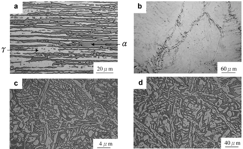
Fig. 2 compares the microstructures of the steel plate
and laser weld before and after 1050C post-heat
treat-ment. For the steel plate, a severely elongated band struc-ture still prevailed in spite of soaking at 1050C for
60 min. This indicated that the a/c banded structure was hard to be eliminated by the conventional heat treatment. Moreover, the steel plate after 1050C/60 min treatment
consisted of coarser and greater amount of austenite as compared with the as-received steel plate. In contrast, the
microstructures of the fusion zone were more irregular in morphologies. Little grain boundary c and its side plate together with some c precipitating intragranularly within
the a matrix were observed in the as-welded weld
(Fig. 2b). After a short time post-weld heat treatment,
pre-dominantly the precipitation of blockycwithin the matrix
(Fig. 2c) accounted for the great increase in theccontent of
the fusion zone, as listed inTable 2. With increasing soak-ing time, the cbecame coarser and greater but varied in a slower rate.
3.2. Charpy impact test
Charpy impact toughness of the steel plate and laser weld with/without 1050C post-heat treatments is listed
inTable 3. The orientation with respect to the rolling
direc-tion had a great influence on the impact toughness of the base plate. Continuous tearing of the banded structure in the T specimen in contrast to the presence of the crack absorber (c) in the L specimen accounted for the lower impact toughness of the former. The influence of specimen orientation on the impact toughness could be corroborated with previous observation that post-treatment did not remove the banded structure. Post-heated steel plate gave a considerably higher c content, but the impact energy was even lowered. The reasons could be partly attributed to coarse banded microstructures in the post-heated steel
Table 2
Thea/cratio of various specimens determined by Ferrite scope
Specimen B B60 AW AW15 AW30 AW45 AW60
a/c 57/43 ± 0.7 40/60 ± 0.7 75/25 ± 2.2 53/47 ± 2.0 51/49 ± 2.0 47/53 ± 1.7 45/55 ± 1.7
plate. In contrast, the great increase in c content and change in c morphology in the post-heated fusion zone was responsible for the improved weld’s impact toughness, even after short time post-weld heat treatment. Fig. 3
shows the impact-fractured appearance of various speci-mens. The steel plates with the banded structure all revealed ductile dimple fracture after SEM examinations
(Fig. 3a). In case of the as-welded weld, the presence of fine
facet mixed with small dimple fracture might be attributed to the inherently lowccontent (Fig. 3b). Extensivelyc pre-cipitation in the granular and island forms within the matrix accounted for the great increase in impact energy, and the presence of numerous fine dimples in the post-heated welds (Fig. 3c).
3.3. Fatigue crack growth test
The fatigue crack growth behaviors of DSS steel plate and laser weld tested in laboratory air are shown in
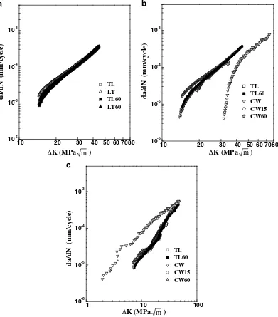
Fig. 4. The measured FCGR in the DSS was the result of
the overall crack growth rate contributed bycandaphases simultaneously. The TL and LT specimens exhibited the same fatigue crack growth behavior, as shown in Fig. 4a. As mentioned previously, the specimen orientation had a great influence on the impact energy but its effect on FCGR of the as-received steel was minor. This meant that the impact energy could not be used as an indicator to antici-pate the crack growth behavior of the DSS. Besides, raising theccontent by post-heating the steel plate (i.e. TL60 and LT60 specimens) could only reduce the FCGR of the alloy slightly in the lowDKregime (Fig. 4a). Therefore, it seemed that the variation ofccontent and morphology within cer-tain realm had limited effects on the FCGR of this alloy.
For the as-welded weld (CW), the FCGR increased sig-nificantly with increasing DK (Fig. 4b. Also, the fatigue threshold of the CW specimen was clearly higher than that of the other specimens. The measurements of residual stres-ses in the as-welded fusion zone indicated that principal residual stresses were with the magnitude of 348 MPa in the direction parallel to the welding direction (longitudinal direction) and 47 MPa transverse to it. After post-weld heat treatment for 30 min, residual stresses in the fusion zone were reduced to 122 MPa in the longitudinal direction and 57 MPa in the transverse direction. The presence of tensile residual stresses in both directions within the as-welded fusion zone was found not to accelerate the crack growth. Similar results also point out that the FCGRs in the fusion zone and the heat-affected zone are lower than that of the base metal for the as-welded A514 weld [15]. Reduced FCGR in the fusion zone of a weld can be
attrib-uted to the redistribution of residual stresses after introduc-ing a fatigue crack into the weld metal[16]. The residual stress field in the as-welded weld tends to bend and rotate the crack face, leading to crack closure and resulting in the reduced FCGR[16]. In previous study[17], the induced compressive residual stresses ahead of crack front can obvi-ously retard the crack growth of laser-treated 304 SS as the crack grows in the direction normal to the laser scan direc-tion. Moreover, after stress relief heat treatment the weld is reported to exhibit a considerable increase in FCGR as compared with the as-welded weld [15]. It could be the
Table 3
Charpy impact toughness of the steel plate and laser weld with/without 1050C post-heat treatments
Specimen L T L60 T60 W W15 W60
Impact Energy (J) 143 90 110 88 95 136 144
residual stresses in the post-heated welds, even for the weld heated at 1050C for as short as 15 min, were lower
enough hence did not cause an obvious crack closure. Therefore, the initially high resistance to crack growth dis-appeared in the lowDKregion. In this work, residual weld-ing stresses showed a more significant effect on the FCGR of the DSS weld than the microstructural factors did. The post-heated welds (CW15 & CW60) and steel plates (TL & TL60) had quite different microstructures and impact ener-gies, yet their fatigue crack growth characteristics were sim-ilar to each other, as shown inFig. 4b.
When da/dN was represented in term ofDKeff(Fig. 4c), the difference in FCGR between various specimens was reduced. It was worth mentioning that CW specimen behaved the highest FCGR among the specimens. In fact, the use of crack closure did not completely reflect the crack growth behavior of the CW specimen. Fig. 5 shows the
degree of crack closure in various specimens. TheUvalue of CW specimen was obviously lower than other speci-mens, resulting in a high resistance to crack growth. In comparison with the TL specimen, all post-heated speci-mens, including the steel plate and welds, had slightly smal-ler U values, especially in the low DK range. The initial distinction in Uvalue between post-heated and TL speci-mens led to a difference in FCGR between them. The results also indicated that the crack opening level of post-heated specimens increased rapidly with increasing DK range, and finally reached the level of the TL specimen.
3.4. X-ray diffraction
The strain-induced martensite has been shown to influence the fatigue crack growth behavior of metasta-ble stainless steels [18–21]. Such transformation will
10 20 30 40 50 60 7080
10-6 10-5 10-4 10-3
TL TL60 CW CW15 CW60
da/dN (mm/cycle)
10 20 30 40 50 60 7080
10-6 10-5 10-4 10-3
TL
m
LT TL60 LT60
da/dN (mm/cycle)
ΔK (MPa )
1 10 100
10-6 10-5 10-4 10-3
TL TL60 CW CW15 CW60
da/dN (mm/cycle)
m ΔK (MPa )
m ΔK (MPa )
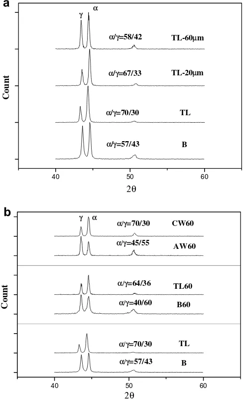
contribute to premature fatigue crack closure.Fig. 6is the X-ray diffraction pattern of various specimens measured on the fatigue-fractured surface in comparison with the counterpart specimen. The induced martensite formed on the crack surface was related to the varied a/c ratio. As shown in Fig. 6a, the as-received steel plate (B) con-sisted of nearly balanced a/c ratio (57/43). Moreover, the a/c ratio changed to about 70/30 on the fatigue-frac-tured surface of TL specimen. The increased a content actually revealed that a small portion of c did transform to martensite as a result of cyclic straining. When approx-imately 20lm of the material on the fatigue-fractured sur-face was removed, X-ray diffraction pattern (TL-20lm) showed less fraction of ferromagnetic phases present at this depth. At a depth of about 60lm (TL-60lm) below the crack surface, the a/c ratio reversed to that of the steel plate (B). Therefore, the results indicated that a small portion of austenite had transformed to martensite within a definite depth below the crack surface.
The ease ofctoatransformation depends on thec sta-bility, imposed strain and working temperature, etc. A les-ser austenite stabilizer within the c phase resulted in a higher ability of it to undergo martensitic transformation. As listed inTable 2, B60 specimens consisted of a greater
c content than the B. Therefore, the c in the former was more likely to undergo transformation than that of the lat-ter aflat-ter cyclic straining, owing to the lean ofcstabilizer in the former. As shown in Fig. 6b, it was noted that about 24% increase inacontent in the B60 specimen, in contrast to 13% in the B. The post-treated weld also showed the trend of strain-induced transformation as the steel plate. It was deduced that such a phase transformation within a thin layer enhanced the crack closure, and accounted for the difference in crack growth behavior between TL and post-treated specimens (TL60, CW60) in the lowDKrange. Such a thin layer of transformation was anticipated to reduce its influence on the FCGR at the high DK range or large crack opening level.
3.5. Fractographs
Fig. 7 shows the typical macroscopic fatigue-fractured
appearance of the specimens as well as the corresponding fracture surface roughness. The results revealed that the fracture surface of post-heated welds (Fig. 7a) was much rougher and irregular in comparison with that of the steel plate (Fig. 7b) over the entire surface. The rough appear-ance of CW60 specimens could be attributed to the inher-ently coarse solidified structure in the fusion zone. Such a coarse structure was more likely to have a deflected crack path, leading to a slightly higher crack closure [22–24]. The variation of surface roughness and amplitude
(Fig. 7c) confirmed such evidences. Therefore, the CW 60
specimen with a zig–zag crack path behaved a lower FCGR than the base plate, especially in the lowDKrange.
10 15 20 25 30 35 40 45 50 55 60 65 70 75
Fig. 5. The development of crack closure in distinct specimens.
40 50 60
TL CW60
Ra (µm)
(µm)
3.33 12.35
Rz 21.2 54.03
-150 -100 -50 0 50 100 150
m
22 20
18 16
14.5
Roughness (
µ
m)
TL CW60
Specimen
Roughnes
1cm 1cm
m ΔK (MPa )
Fig. 7. The typically macroscopic fatigue-fractured appearance of (a) steel plate, (b) 1050C/60 min post-heated weld, (c) the variation of surface roughness in corresponding specimens and (d) the Ra and Rz values of the specimens.
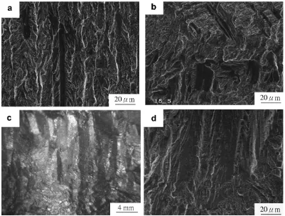
Fig. 8 shows the fracture appearance of various speci-mens. Fracture appearance of the base plate consisted of mainly transgranular fatigue fracture and small amount of elongated faceted failure (Fig. 8a). The aspect and shape of faceted flats were inter-dispersed on fracture surface of the laser-welded specimens (Fig. 8b). Moreover, the extent of flat fracture was wider for the weld relative to the base plate. In previous researches [25], the a/c interface is the easy path for crack propagation. Therefore, acicular and blocky c inter-dispersed randomly in the fusion zone of DSS welds tended to exhibit disorder facet fracture as com-pared with the banded steel plate. It was deduced that the irregular separation ofa/c interface (Fig. 8b) contributed to the deflected crack growth, resulting in the formation of rougher surface in the CW60 specimen. It was noted that coarse columnar structures were seen on the macroscopic fracture appearance of CW specimen (Fig. 8c). Detailed examination showed brittle facet failure extensively
(Fig. 8d). It was implied that the higher brittleness of
CW specimens associated with abnormal high a content, accounted for the inherently higher FCGR relative to other specimens as shown inFig. 4c.
4. Conclusions
(1) Thea/cratio in the fusion zone of the as-welded weld was drastically increased as compared with the bal-anced steel plate. The short time post-weld treatment at 1050C could effectively restore the a/c ratio of
the fusion zone to comparable conditions. The great increase in c content and change in c morphology was responsible for the improved weld’s impact tough-ness, even after short time post-weld heat treatment. (2) Fatigue crack growth tests revealed that the variation
of c content and morphology within certain realm had limited effects on the FCGR of the steel plates and welds. Residual welding stresses played a more significant affection on the FCGR of the DSS weld than microstructural factors did. Plastic deformation induced martensitic transformation within a thin layer caused the crack closure and accounted for the difference in crack growth behavior between the specimens, especially in the low DK range. Coarse
columnar structure in the DSS weld was more likely to have a tortuous crack path over the entire DK range in comparison with the steel plate.
Acknowledgements
The authors gratefully acknowledge the financial sup-port of this study by National Science Council of Republic, China (NSC 92-2216-E-019-009).
References
[1] Nilsson JO. Mater Sci Technol 1992;8:685.
[2] Dupoiron F, Audouard JP. Scand J Metall 1996;25:95. [3] Zheng W, Hardie D. Corrosion 1991;47:792.
[4] Tsay LW, Young MC, Shin C-S, Chan SLI. Fatigue Fract Eng Mater Struct [submitted for publication].
[5] Berglund G, Wilhelmsson P. Mater Des 1989;10:23.
[6] Ku JS, Ho NJ, Tjong SC. J Mater Process Technol 1997;63:770. [7] Kordatos JD, Fourlaris G, Papadimitrious G. Scripta Mater
2001;44:401.
[8] Oates WR, Saitta AM, editors. Welding Handbook, 8th ed., Vol. 4. Maimi: AWS; 1996. p. 233.
[9] Capello E, Chiarello P, Previtali, Vedani M. Mater Sci Eng A 2003;351:334.
[10] Wu HC, Tsay LW, Chen C. ISIJ Inter 2004;44:1720.
[11] Young MC, Chan SLI, Tsay LW, Shin C-S. Mater Chem Phys 2005;91:21.
[12] Saxena A, Hudak SJ. Int J Fract 1978;14:453. [13] Tsay LW, Lin HH, Shiue RK. Corr Sci 2004;46:2651.
[14] Tsay LW, Young MC, Chou FY, Shiue RK. Mater Chem Phys 2004;88:348.
[15] Parry M, Nordberg H, Hertzberg RW. Weld J 1972;51:485. [16] Shi YW, Chen BY, Zhang JX. Eng Fract Mech 1990;36:893. [17] Shiue RK, Chang CT, Young MC, Tsay LW. Mater Sci Eng A
2004;364:101.
[18] Schuster G, Altstetter C. Metall Trans 1983;14A:2077. [19] Tsay LW, Young MC, Chen C. Corr Sci 2003;45:1985. [20] Mei Z, Morris JW. Metall Trans 1990;21A:3137.
[21] Tsay LW, Liu YC, Lin D-Y, Young MC. Mater Sci Eng A 2004;384:177.
[22] Lanes L, Mateo A, Violan P, Me´ndez J, Anglada M. Mater Sci Eng A 1997;234–236:850.
[23] Kang TH, Li DM, Lee YD, Lee CS. Mater Sci Eng A 1998;251:192. [24] Iturgoyen L, Anglada M. Fatigue Fract Eng Mater Struct
1997;20:917.
