About This eBook
ePUB is an open, industry-standard format for eBooks. However, support of ePUB and its many features varies across reading devices and applications. Use your device or app settings to customize the presentation to your liking. Settings that you can customize often include font, font size, single or double column, landscape or portrait mode, and figures that you can click or tap to enlarge. For additional information about the settings and features on your reading device or app, visit the device manufacturer’s Web site.
Many titles include programming code or configuration examples. To optimize the presentation of these elements, view the eBook in single-column, landscape mode and adjust the font size to the smallest setting. In addition to presenting code and configurations in the reflowable text format, we have included images of the code that mimic the presentation found in the print book; therefore, where the reflowable format may compromise the presentation of the code listing, you will see a “Click here to view code image” link. Click the link to view the print-fidelity code image. To return to the
Routing and Switching Essentials Companion
Guide
Cisco Networking Academy
Cisco Press 800 East 96th Street
Routing and Switching Essentials Companion Guide
Cisco Networking AcademyCopyright© 2014 Cisco Systems, Inc. Published by:
Cisco Press
800 East 96th Street
Indianapolis, IN 46240 USA
All rights reserved. No part of this book may be reproduced or transmitted in any form or by any means, electronic or mechanical, including photocopying, recording, or by any information storage and retrieval system, without written permission from the publisher, except for the inclusion of brief quotations in a review.
Printed in the United States of America Third Printing: September 2015
Library of Congress Control Number: 2013956689 ISBN-13: 978-1-58713-318-3
Business Operation Manager, Cisco Press
Designer
This book is designed to provide information about the Cisco Networking Academy Routing and Switching Essentials course. Every effort has been made to make this book as complete and as accurate as possible, but no warranty or fitness is implied.
The information is provided on an “as is” basis. The authors, Cisco Press, and Cisco Systems, Inc. shall have neither liability nor responsibility to any person or entity with respect to any loss or
damages arising from the information contained in this book or from the use of the discs or programs that may accompany it.
The opinions expressed in this book belong to the author and are not necessarily those of Cisco Systems, Inc.
This book is part of the Cisco Networking Academy® series from Cisco Press. The products in this series support and complement the Cisco Networking Academy curriculum. If you are using this book outside the Networking Academy, then you are not preparing with a Cisco trained and authorized Networking Academy provider.
For more information on the Cisco Networking Academy or to locate a Networking Academy, Please visit www.cisco.com/edu.
Trademark Acknowledgements
All terms mentioned in this book that are known to be trademarks or service marks have been appropriately capitalized. Cisco Press or Cisco Systems, Inc., cannot attest to the accuracy of this information. Use of a term in this book should not be regarded as affecting the validity of any trademark or service mark.
Special Sales
For government sales inquiries, please contact [email protected].
For questions about sales outside the U.S., please contact [email protected].
Feedback Information
At Cisco Press, our goal is to create in-depth technical books of the highest quality and value. Each book is crafted with care and precision, undergoing rigorous development that involves the unique expertise of members from the professional technical community.
Readers’ feedback is a natural continuation of this process. If you have any comments regarding how we could improve the quality of this book, or otherwise alter it to better suit your needs, you can contact us through email at [email protected]. Please make sure to include the book title and ISBN in your message.
We greatly appreciate your assistance.
Cisco has more than 200 offices worldwide. Addresses, phone numbers, and fax numbers are listed on the Cisco Website at www.cisco.com/go/offices.
©2007 Cisco Systems, Inc. All rights reserved. CCVP, the Cisco logo, and the Cisco Square Bridge logo are trademarks of Cisco Systems, Inc.; Changing the Way We Work, Live, Play, and Learn is a service mark of Cisco Systems, Inc.; and Access Registrar, Aironet, BPX, Catalyst, CCDA, CCDP CCIE, CCIP CCNA, CCNP CCSP Cisco, the Cisco Certified Internetwork Expert logo, Cisco IOS, Cisco Press, Cisco Systems, Cisco Systems Capital, the Cisco Systems logo, Cisco Unity,
Enterprise/Solver, EtherChannel, EtherFast, EtherSwitoh, Fast Step, Follow Me Browsing,
FormShare, GigaDrive, GigaStack HomeLink Internet Quotient, IOS, IP/TV iQ Expertise, the iQ logo iQ Net Readiness Scorecard, iQuick Study, LightStream, Linksys, MeetingPlace, MGX, Networking Academy, Network Registrar, Packet, PIX, ProConnect, RateMUX, ScriptShare, SlideCast,
SMARTnet, StackWise, The Fastest Way to Increase Your Internet Quotient, and TransPath are
registered trademarks of Cisco Systems, Inc. and/or its affiliates in the United States and certain other countries
All other trademarks mentioned in this document or Website are the property of their respective
About the Contributing Authors
Scott Empson is the chair of the Bachelor of Applied Information Systems Technology degree program at the Northern Alberta Institute of Technology in Edmonton, Alberta, Canada, where he teaches Cisco routing, switching, network design, and leadership courses in a variety of different programs (certificate, diploma, and applied degree) at the postsecondary level.
Scott is also the program coordinator of the Cisco Networking Academy Program at NAIT, an Area Support Centre for the province of Alberta. He has been with the Cisco Academy since 2000.
He has a Masters of Education degree along with three undergraduate degrees: a Bachelor of Arts, with a major in English; a Bachelor of Education, again with a major in English/Language Arts; and a Bachelor of Applied Information Systems Technology, with a major in Network Management. He currently holds several industry certifications, including CCNP, CCDP, CCAI, C|EH and Network+. Before instructing at NAIT, he was a junior/senior high school English/Language Arts/Computer Science teacher at different schools throughout Northern Alberta.
Scott lives in Edmonton, Alberta, with his wife Trina and two children, Zachariah and Shaelyn. Cheryl Schmidt is a professor at Florida State College at Jacksonville in Jacksonville, Florida, where she teaches courses in networking and PC repair. She has been teaching the academy curriculum since one of the earliest versions.
Cheryl has authored multiple books in such areas as PC repair, networking, and voice over IP. Cheryl also participates on a Cisco Academy team as a subject matter expert on a team that develops state-of-the-art assessments and courseware.
Outside of her academic responsibilities, Cheryl is currently pursuing a Ph.D. in information
Contents at a Glance
Introduction
Chapter 1: Introduction to Switched Networks
Chapter 2: Basic Switching Concepts and Configuration Chapter 3: VLANs
Chapter 4: Routing Concepts Chapter 5: Inter-VLAN Routing Chapter 6: Static Routing
Chapter 7: Routing Dynamically Chapter 8: Single-Area OSPF Chapter 9: Access Control Lists Chapter 10: DHCP
Chapter 11: Network Address Translation for IPv4
Appendix A: Answers to the “Check Your Understanding” Questions Glossary
Contents
Introduction
Chapter 1 Introduction to Switched Networks Objectives
Key Terms
Introduction (1.0.1.1) LAN Design (1.1)
Converged Networks (1.1.1)
Growing Complexity of Networks (1.1.1.1) Elements of a Converged Network (1.1.1.2) Borderless Switched Networks (1.1.1.3)
Hierarchy in the Borderless Switched Network (1.1.1.4) Core Distribution Access (1.1.1.5)
Switched Networks (1.1.2)
Role of Switched Networks (1.1.2.1) Form Factors (1.1.2.2)
The Switched Environment (1.2)
Frame Forwarding (1.2.1)
Switching as a General Concept in Networking and Telecommunications (1.2.1.1) Dynamically Populating a Switch MAC Address Table (1.2.1.2)
Switch Forwarding Methods (1.2.1.3)
Key Terms
Introduction (2.0.1.1)
Basic Switch Configuration (2.1)
Switch Boot Sequence (2.1.1.1)
Recovering from a System Crash (2.1.1.2) Switch LED Indicators (2.1.1.3)
Preparing for Basic Switch Management (2.1.1.4)
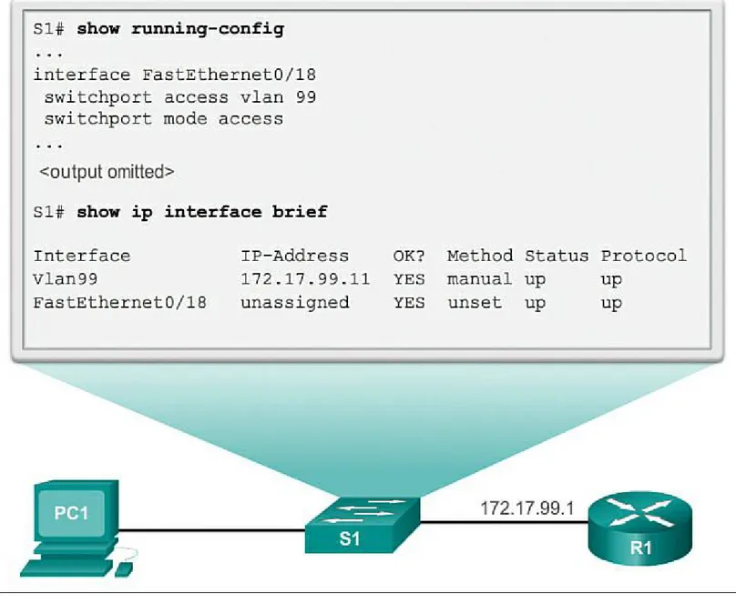
Configuring Basic Switch Management Access with IPv4 (2.1.1.5)
Configure Switch Ports (2.1.2)
Duplex Communication (2.1.2.1)
Configure Switch Ports at the Physical Layer (2.1.2.2)
Duplex and Speed
Auto-MDIX (2.1.2.3)
Verifying Switch Port Configuration (2.1.2.4) Network Access Layer Issues (2.1.2.5)
Troubleshooting Network Access Layer Issues (2.1.2.6)
Switch Security: Management and Implementation (2.2)
Secure Remote Access (2.2.1)
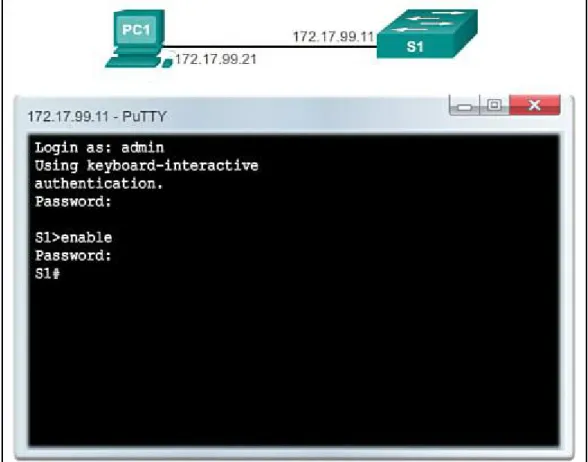
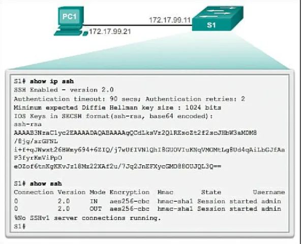
SSH Operation (2.2.1.1) Configuring SSH (2.2.1.2) Verifying SSH (2.2.1.3)
Security Concerns in LANs (2.2.2)
Common Security Attacks: MAC Address Flooding (2.2.2.1) Common Security Attacks: DHCP Spoofing (2.2.2.2)
Common Security Attacks: Leveraging CDP (2.2.2.3)
Security Best Practices (2.2.3)
Best Practices (2.2.3.1)
Network Security Tools and Testing (2.2.3.2) Network Security Audits (2.2.3.3)
Switch Port Security (2.2.4)
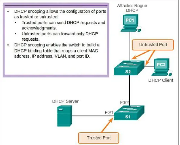
Secure Unused Ports (2.2.4.1) DHCP Snooping (2.2.4.2)
Port Security: Operation (2.2.4.3)
Network Time Protocol (NTP) (2.2.4.8)
VLANs in a Multiswitched Environment (3.1.2)
VLAN Trunks (3.1.2.1)
Controlling Broadcast Domains with VLANs (3.1.2.2)
Network Without VLANs Network with VLANs
Tagging Ethernet Frames for VLAN Identification (3.1.2.3) Native VLANs and 802.1Q Tagging (3.1.2.4)
Tagged Frames on the Native VLAN Untagged Frames on the Native VLAN
Voice VLAN Tagging (3.1.2.5)
Sample Configuration
VLAN Implementations (3.2)
VLAN Ranges on Catalyst Switches (3.2.1.1) Creating a VLAN (3.2.1.2)
Assigning Ports to VLANs (3.2.1.3)
Deleting VLANs (3.2.1.5)
Verifying VLAN Information (3.2.1.6)
VLAN Trunks (3.2.2)
Configuring IEEE 802.1Q Trunk Links (3.2.2.1) Resetting the Trunk to Default State (3.2.2.2) Verifying Trunk Configuration (3.2.2.3)
Dynamic Trunking Protocol (3.2.3)
Introduction to DTP (3.2.3.1)
Negotiated Interface Modes (3.2.3.2)
Troubleshoot VLANs and Trunks (3.2.4)
IP Addressing Issues with VLAN (3.2.4.1) Missing VLANs (3.2.4.2)
Introduction to Troubleshooting Trunks (3.2.4.3) Common Problems with Trunks (3.2.4.4)
Trunk Mode Mismatches (3.2.4.5) Incorrect VLAN List (3.2.4.6)
VLAN Security and Design (3.3)
Switch Spoofing Attack (3.3.1.1) Double-Tagging Attack (3.3.1.2)
PVLAN Edge (3.3.1.3)
Design Best Practices for VLANs (3.3.2)
VLAN Design Guidelines (3.3.2.1)
Functions of a Router (4.1.1)
Characteristics of a Network (4.1.1.1) Why Routing? (4.1.1.2)
Routers Interconnect Networks (4.1.1.4) Routers Choose Best Paths (4.1.1.5) Packet-Forwarding Mechanisms (4.1.1.6)
Connect Devices (4.1.2)
Connect to a Network (4.1.2.1) Default Gateways (4.1.2.2)
Document Network Addressing (4.1.2.3) Enable IP on a Host (4.1.2.4)
Device LEDs (4.1.2.5) Console Access (4.1.2.6)
Enable IP on a Switch (4.1.2.7)
Basic Settings on a Router (4.1.3)
Configure Basic Router Settings (4.1.3.1) Configure an IPv4 Router Interface (4.1.3.2) Configure an IPv6 Router Interface (4.1.3.3) Configure an IPv4 Loopback Interface (4.1.3.4)
Verify Connectivity of Directly Connected Networks (4.1.4)
Verify Interface Settings (4.1.4.1) Verify IPv6 Interface Settings (4.1.4.2) Filter Show Command Output (4.1.4.3) Command History Feature (4.1.4.4)
Switching Packets Between Networks (4.2.1)
Router Switching Function (4.2.1.1) Send a Packet (4.2.1.2)
Forward to the Next Hop (4.2.1.3) Packet Routing (4.2.1.4)
Analyze the Routing Table (4.3.1)
The Routing Table (4.3.1.1) Routing Table Sources (4.3.1.2)
Directly Connected Routes (4.3.2)
Directly Connected Interfaces (4.3.2.1)
Directly Connected Routing Table Entries (4.3.2.2) Directly Connected Examples (4.3.2.3)
Directly Connected IPv6 Example (4.3.2.4)
Statically Learned Routes (4.3.3)
Static Routes (4.3.3.1)
Static Route Examples (4.3.3.2) Static IPv6 Route Examples (4.3.3.3)
Dynamic Routing Protocols (4.3.4)
Dynamic Routing (4.3.4.1)
IPv4 Routing Protocols (4.3.4.2)
IPv4 Dynamic Routing Examples (4.3.4.3) IPv6 Routing Protocols (4.3.4.4)
IPv6 Dynamic Routing Examples (4.3.4.5)
Summary (4.4)
What Is Inter-VLAN Routing? (5.1.1.1) Legacy Inter-VLAN Routing (5.1.1.2)
Router-on-a-Stick Inter-VLAN Routing (5.1.1.3) Multilayer Switch Inter-VLAN Routing (5.1.1.4)
Configure Legacy Inter-VLAN Routing (5.1.2)
Configure Legacy Inter-VLAN Routing: Preparation (5.1.2.1)
Configure Legacy Inter-VLAN Routing: Switch Configuration (5.1.2.2)
Configure Legacy Inter-VLAN Routing: Router Interface Configuration (5.1.2.3)
Configure Router-on-a-Stick Inter-VLAN Routing (5.1.3)
Configure Router-on-a-Stick: Switch Configuration (5.1.3.2)
Configure Router-on-a-Stick: Router Subinterface Configuration (5.1.3.3) Configure Router-on-a-Stick: Verifying Subinterfaces (5.1.3.4)
Configure Router-on-a-Stick: Verifying Routing (5.1.3.5)
Ping Test
Errors with IP Addresses and Subnet Masks (5.2.2.1)
Verifying IP Address and Subnet Mask Configuration Issues (5.2.2.2)
Layer 3 Switching (5.3)
Introduction to Layer 3 Switching (5.3.1.1)
Inter-VLAN Routing with Switch Virtual Interfaces (5.3.1.2, 5.3.1.3) Inter-VLAN Routing with Routed Ports (5.3.1.4)
Routed Ports and Access Ports on a Switch
Configuring Static Routes on a Catalyst 2960 (5.3.1.5)
Troubleshoot Layer 3 Switching (5.3.2)
Layer 3 Switch Configuration Issues (5.3.2.1)
Example: Troubleshooting Layer 3 Switching (5.3.2.2)
Why Use Static Routing? (6.1.1.2) When to Use Static Routes (6.1.1.3)
Types of Static Routes
Configure IPv4 Static Routes (6.2.1) ip route Command (6.2.1.1)
Next-Hop Options (6.2.1.2)
Configure a Next-Hop Static Route (6.2.1.3)
Configure a Directly Connected Static Route (6.2.1.4) Configure a Fully Specified Static Route (6.2.1.5) Verify a Static Route (6.2.1.6)
Configure IPv4 Default Routes (6.2.2)
Default Static Route (6.2.2.1)
Configure a Default Static Route (6.2.2.2) Verify a Default Static Route (6.2.2.3)
Configure IPv6 Static Routes (6.2.3)
The ipv6 route Command (6.2.3.1) Next-Hop Options (6.2.3.2)
Configure a Next-Hop Static IPv6 Route (6.2.3.3)
Configure a Directly Connected Static IPv6 Route (6.2.3.4) Configure a Fully Specified Static IPv6 Route (6.2.3.5) Verify IPv6 Static Routes (6.2.3.6)
Configure IPv6 Default Routes (6.2.4)
Default Static IPv6 Route (6.2.4.1)
Configure a Default Static IPv6 Route (6.2.4.2) Verify a Default Static Route (6.2.4.3)
Review of CIDR and VLSM (6.3)
Classful Network Addressing (6.3.1.1) Classful Subnet Masks (6.3.1.2)
Classful Routing Protocol Example (6.3.1.3) Classful Addressing Waste (6.3.1.4)
Classless Inter-Domain Routing (6.3.2.1) CIDR and Route Summarization (6.3.2.2) Static Routing CIDR Example (6.3.2.3)
Classless Routing Protocol Example (6.3.2.4)
VLSM (6.3.3)
Configure IPv4 Summary Routes (6.4.1) Route Summarization (6.4.1.1)
Calculate a Summary Route (6.4.1.2)
Summary Static Route Example (6.4.1.3)
Configure IPv6 Summary Routes (6.4.2)
Summarize IPv6 Network Addresses (6.4.2.1) Calculate IPv6 Summary Addresses (6.4.2.2) Configure an IPv6 Summary Address (6.4.2.3)
Configure Floating Static Routes (6.4.3)
Floating Static Routes (6.4.3.1)
Configure a Floating Static Route (6.4.3.2) Test the Floating Static Route (6.4.3.3)
Troubleshoot Static and Default Route Issues (6.5)
Static Routes and Packet Forwarding (6.5.1.1) Troubleshoot a Missing Route (6.5.2.1)
Solve a Connectivity Problem (6.5.2.2)
Dynamic Routing Protocol Operation (7.1.1)
The Evolution of Dynamic Routing Protocols (7.1.1.1) Purpose of Dynamic Routing Protocols (7.1.1.2)
The Role of Dynamic Routing Protocols (7.1.1.3)
Dynamic Versus Static Routing (7.1.2)
Using Static Routing (7.1.2.1) Static Routing Scorecard (7.1.2.2)
Using Dynamic Routing Protocols (7.1.2.3) Dynamic Routing Scorecard (7.1.2.4)
Routing Protocol Operating Fundamentals (7.1.3)
Dynamic Routing Protocol Operation (7.1.3.1) Cold Start (7.1.3.2)
Network Discovery (7.1.3.3)
Exchanging the Routing Information (7.1.3.4) Achieving Convergence (7.1.3.5)
Types of Routing Protocols (7.1.4)
Classifying Routing Protocols (7.1.4.1) IGP and EGP Routing Protocols (7.1.4.2) Distance Vector Routing Protocols (7.1.4.3) Link-State Routing Protocols (7.1.4.4)
Classful Routing Protocols (7.1.4.5) Classless Routing Protocols (7.1.4.6) Routing Protocol Characteristics (7.1.4.7) Routing Protocol Metrics (7.1.4.8)
Distance Vector Routing Protocol Operation (7.2.1)
Distance Vector Technologies (7.2.1.1) Distance Vector Algorithm (7.2.1.2)
Types of Distance Vector Routing Protocols (7.2.2)
Routing Information Protocol (7.2.2.1)
Enhanced Interior-Gateway Routing Protocol (7.2.2.2)
RIP and RIPng Routing (7.3)
Router RIP Configuration Mode (7.3.1.1) Advertising Networks (7.3.1.2)
Examining Default RIP Settings (7.3.1.3) Enabling RIPv2 (7.3.1.4)
Propagating a Default Route (7.3.1.7)
Configuring the RIPng Protocol (7.3.2)
Advertising IPv6 Networks (7.3.2.1)
Examining the RIPng Configuration (7.3.2.2)
Link-State Dynamic Routing (7.4)
Shortest Path First Protocols (7.4.1.1) Dijkstra’s Algorithm (7.4.1.2)
Building the Link-State Packet (7.4.2.4) Flooding the LSP (7.4.2.5)
Building the Link-State Database (7.4.2.6) Building the SPF Tree (7.4.2.7)
Adding OSPF Routes to the Routing Table (7.4.2.8)
Why Use Link-State Routing Protocols (7.4.3)
Why Use Link-State Protocols? (7.4.3.1)
Disadvantages of Link-State Protocols (7.4.3.2) Protocols That Use Link-State (7.4.3.3)
Parts of an IPv4 Route Entry (7.5.1)
Routing Table Entries (7.5.1.1) Directly Connected Entries (7.5.1.2) Remote Network Entries (7.5.1.3)
Dynamically Learned IPv4 Routes (7.5.2)
Routing Table Terms (7.5.2.1) Ultimate Route (7.5.2.2)
Level 1 Route (7.5.2.3)
Level 1 Parent Route (7.5.2.4) Level 2 Child Route (7.5.2.5)
The IPv4 Route Lookup Process (7.5.3)
Route Lookup Process (7.5.3.1) Best Route = Longest Match (7.5.3.2)
Analyze an IPv6 Routing Table (7.5.4)
Remote IPv6 Network Entries (7.5.4.3)
Single-Area and Multiarea OSPF (8.1.1.5)
OSPF Messages (8.1.2)
Encapsulating OSPF Messages (8.1.2.1) Types of OSPF Packets (8.1.2.2)
Hello Packet (8.1.2.3) OSPF DR and BDR (8.1.3.3)
Synchronizing OSPF Databases (8.1.3.4)
Configuring Single-Area OSPFv2 (8.2.1)
OSPF Network Topology (8.2.1.1)
Router OSPF Configuration Mode (8.2.1.2) Router IDs (8.2.1.3)
Modifying a Router ID (8.2.1.5)
Using a Loopback Interface as the Router ID (8.2.1.6)
Configure Single-Area OSPFv2 (8.2.2)
Enabling OSPF on Interfaces (8.2.2.1) Wildcard Mask (8.2.2.2)
The network Command (8.2.2.3) Passive Interface (8.2.2.4)
Configuring Passive Interfaces (8.2.2.5)
OSPF Cost (8.2.3)
OSPF Metric = Cost (8.2.3.1) OSPF Accumulates Costs (8.2.3.2)
Adjusting the Reference Bandwidth (8.2.3.3)
Adjusting the Reference Bandwidth
Default Interface Bandwidths (8.2.3.4)
Adjusting the Interface Bandwidths (8.2.3.5) Manually Setting the OSPF Cost (8.2.3.6)
Verify OSPF (8.2.4)
Verify OSPF Neighbors (8.2.4.1)
Verify OSPF Protocol Settings (8.2.4.2) Verify OSPF Process Information (8.2.4.3) Verify OSPF Interface Settings (8.2.4.4)
OSPFv2 vs. OSPFv3 (8.3.1)
OSPFv3 (8.3.1.1)
Similarities Between OSPFv2 to OSPFv3 (8.3.1.2) Differences Between OSPFv2 and OSPFv3 (8.3.1.3) Link-Local Addresses (8.3.1.4)
Configuring OSPFv3 (8.3.2)
OSPFv3 Network Topology (8.3.2.1) Link-Local Addresses (8.3.2.2)
Assigning Link-Local Addresses (8.3.2.3) Configuring the OSPFv3 Router ID (8.3.2.4) Modifying an OSPFv3 Router ID (8.3.2.5) Enabling OSPFv3 on Interfaces (8.3.2.6)
Verify OSPFv3 (8.3.3)
Verify OSPFv3 Neighbors (8.3.3.1)
Verify the IPv6 Routing Table (8.3.3.4) Chapter 9 Access Control Lists
Objectives Key Terms
Introduction (9.0.1.1) IP ACL Operation (9.1)
What Is an ACL? (9.1.1.1) A TCP Conversation (9.1.1.2)
TCP Communication
Packet Filtering (9.1.1.3, 9.1.1.4) ACL Operation (9.1.1.5)
Standard Versus Extended IPv4 ACLS (9.1.2)
Types of Cisco IPv4 ACLs (9.1.2.1)
Standard ACLs Extended ACLs
Numbering and Naming ACLs (9.1.2.2)
Wildcard Masks in ACLs (9.1.3)
Introducing ACL Wildcard Masking (9.1.3.1)
Wildcard Masking Using a Wildcard Mask
Wildcard Mask Examples (9.1.3.2)
Wildcard Masks to Match IPv4 Subnets Wildcard Masks to Match Ranges
Calculating the Wildcard Mask (9.1.3.3) Wildcard Mask Keywords (9.1.3.4)
Wildcard Bit Mask Keywords
Examples Wildcard Mask Keywords (9.1.3.5)
The any and host Keywords
Guidelines for ACL Creation (9.1.4)
ACL Best Practices (9.1.4.2)
Guidelines for ACL Placement (9.1.5)
Where to Place ACLs (9.1.5.1) Standard ACL Placement (9.1.5.2) Extended ACL Placement (9.1.5.3)
Standard IPv4 ACLs (9.2)
Entering Criteria Statements (9.2.1.1)
Configuring a Standard ACL – Standard ACL Logic (9.2.1.2)
Configuring a Standard ACL – Configuring Standard ACLs (9.2.1.3) Internal Logic (9.2.1.4)
Applying Standard ACLs to Interfaces – Standard ACL Configuration Procedures (9.2.1.5, 9.2.1.6)
Creating Named Standard ACLs (9.2.1.7) Commenting ACLs (9.2.1.8)
Modify IPv4 ACLs (9.2.2)
Editing Standard Numbered ACLs (9.2.2.1, 9.2.2.2)
Method 1: Using a Text Editor
Method 2: Using the Sequence Number
Editing Standard Named ACLs (9.2.2.3) Verifying ACLs (9.2.2.4)
ACL Statistics (9.2.2.5)
Standard ACL Sequence Numbers (9.2.2.6)
Securing VTY Ports with a Standard IPv4 ACL (9.2.3)
Configuring a Standard ACL to Secure a VTY Port (9.2.3.1) Verifying a Standard ACL Used to Secure a VTY Port (9.2.3.2)
Structure of an Extended IPv4 ACL (9.3.1)
Extended ACLs – Testing Packets with Extended ACLs (9.3.1.1) Extended ACLs – Testing for Ports and Services (9.3.1.2)
Configure Extended IPv4 ACLs (9.3.2) Configuring Extended ACLs (9.3.2.1)
Applying Extended ACLs to Interfaces (9.3.2.2) Filtering Traffic with Extended ACLs (9.3.2.3) Creating Named Extended ACLs (9.3.2.4) Verifying Extended ACLs (9.3.2.5)
Editing Extended ACLs (9.3.2.6)
Troubleshoot ACLs (9.4)
ACL Logic Operations (9.4.1.2)
Standard ACL Decision Process (9.4.1.3) Extended ACL Decision Process (9.4.1.4)
Common ACL Errors (9.4.2)
Troubleshooting Common ACL Errors - Example 1 (9.4.2.1) Troubleshooting Common ACL Errors - Example 2 (9.4.2.2) Troubleshooting Common ACL Errors - Example 3 (9.4.2.3) Troubleshooting Common ACL Errors - Example 4 (9.4.2.4) Troubleshooting Common ACL Errors - Example 5 (9.4.2.5)
IPv6 ACLs (9.5)
Type of IPv6 ACLs (9.5.1.1)
Comparing IPv4 and IPv6 ACLs (9.5.1.2) Configuring IPv6 Topology (9.5.2.1) Configuring IPv6 ACLs (9.5.2.2)
Applying an IPv6 ACL to an Interface (9.5.2.3) IPv6 ACL Examples (9.5.2.4)
Dynamic Host Configuration Protocol v4 (10.1)
Introducing DHCPv4 (10.1.1.1) DHCPv4 Operation (10.1.1.2)
Lease Origination Lease Renewal
DHCPv4 Message Format (10.1.1.3)
Configuring a Basic DHCPv4 Server (10.1.2)
Configuring a Basic DHCPv4 Server (10.1.2.1)
DHCPv4 Example
Configuring a Router as DHCPv4 Client (10.1.3.1)
Configuring a SOHO Router as a DHCPv4 Client (10.1.3.2)
Troubleshoot DHCPv4 (10.1.4)
Troubleshooting Tasks (10.1.4.1)
Troubleshooting Task 1: Resolve IPv4 Address Conflicts Troubleshooting Task 2: Verify Physical Connectivity
Troubleshooting Task 3: Test Connectivity Using a Static IP Address Troubleshooting Task 4: Verify Switch Port Configuration
Troubleshooting Task 5: Test DHCPv4 Operation on the Same Subnet or VLAN
Verify Router DHCPv4 Configuration (10.1.4.2) Debugging DHCPv4 (10.1.4.3)
Dynamic Host Configuration Protocol v6 (10.2)
Stateless Address Autoconfiguration (SLAAC) (10.2.1.1) SLAAC Operation (10.2.1.2)
SLAAC and DHCPv6 (10.2.1.3) SLAAC Option (10.2.1.4)
SLAAC Option (Router Advertisement Only)
Stateless DHCPv6 Option (10.2.1.5)
Stateless DHCPv6 Option (Router Advertisement and DHCPv6)
Stateful DHCPv6 Option (10.2.1.6)
Stateful DHCPv6 (DHCPv6 Only)
DHCPv6 Operations (10.2.1.7)
DHCPv6 Communications
Stateless DHCPv6 (10.2.2)
Configuring a Router as a Stateless DHCPv6 Server (10.2.2.1)
DHCPv6 Stateless Server Example
Configuring a Router as a Stateless DHCPv6 Client (10.2.2.2) Verifying Stateless DHCPv6 (10.2.2.3)
Verifying the Stateless DHCPv6 Client
Stateful DHCPv6 Server (10.2.3)
Configuring a Router as a Stateful DHCPv6 Server (10.2.3.1)
DHCPv6 Stateful Server Example
Configuring a Router as a Stateful DHCPv6 Client (10.2.3.2) Verifying Stateful DHCPv6 (10.2.3.3)
Verifying the Stateful DHCPv6 Client
Configuring a Router as a DHCPv6 Relay Agent (10.2.3.4)
Configuring the DHCPv6 Relay Agent
Troubleshoot DHCPv6 (10.2.4)
Troubleshooting Tasks (10.2.4.1)
Troubleshooting Task 1. Resolve Conflicts
Troubleshooting Task 2. Verify Allocation Method
Troubleshooting Task 3. Test with a Static IPv6 Address Troubleshooting Task 4. Verify Switch Port Configuration
Troubleshooting Task 5. Test DHCPv6 Operation on the Same Subnet or VLAN
Verify Router DHCPv6 Configuration (10.2.4.2)
Stateful DHCPv6 Chapter 11 Network Address Translation for IPv4
Objectives Key Terms
Introduction (11.0.1.1) NAT Operation (11.1)
IPv4 Private Address Space (11.1.1.1) What Is NAT? (11.1.1.2)
NAT Terminology (11.1.1.3, 11.1.1.4) How NAT Works (11.1.1.5)
Types of NAT (11.1.2)
Dynamic NAT (11.1.2.2)
Port Address Translation (PAT) (11.1.2.3) Next Available Port (11.1.2.4)
Comparing NAT and PAT (11.1.2.5)
Packets Without a Layer 4 Segment
Benefits of NAT (11.1.3)
Configuring Port Address Translation (PAT) (11.2.3)
Configuring PAT: Address Pool (11.2.3.1)
Configuring PAT for a Pool of Public IP Addresses
Configuring PAT: Single Address (11.2.3.2) Analyzing PAT (11.2.3.3)
Configuring Port Forwarding with IOS (11.2.4.3)
Configuring NAT and IPv6 (11.2.5)
NAT for IPv6? (11.2.5.1)
IPv6 Unique Local Addresses (11.2.5.2) NAT for IPv6 (11.2.5.3)
Troubleshooting NAT (11.3)
Case Study 1
Summary (11.4) Practice
Class Activities Labs
Packet Tracer Activities
Check Your Understanding Questions
Appendix A Answers to the “Check Your Understanding” Questions Glossary
Syntax Conventions
The conventions used to present command syntax in this book are the same conventions used in the IOS Command Reference. The Command Reference describes these conventions as follows:
Boldface indicates commands and keywords that are entered literally as shown. In actual
configuration examples and output (not general command syntax), boldface indicates commands that are manually input by the user (such as a show command).
Italics indicate arguments for which you supply actual values. Vertical bars (|) separate alternative, mutually exclusive elements. Square brackets ([ ]) indicate an optional element.
Braces ({ }) indicate a required choice.
Introduction
Routing and Switching Essentials Companion Guide is the official supplemental textbook for the Cisco Network Academy CCNA Routing and Switching Essentials course. Cisco Networking
Academy is a comprehensive program that delivers information technology skills to students around the world. The curriculum emphasizes real-world practical application, while providing
opportunities for you to gain the skills and hands-on experience needed to design, install, operate, and maintain networks in small- to medium-sized businesses, as well as enterprise and service provider environments.
As a textbook, this book provides a ready reference to explain the same networking concepts, technologies, protocols, and devices as the online curriculum. This book emphasizes key topics, terms, and activities and provides some alternative explanations and examples as compared with the course. You can use the online curriculum as directed by your instructor and then use this Companion Guide’s study tools to help solidify your understanding of all the topics.
Who Should Read This Book
This book is intended for students enrolled in the Cisco Networking Academy Routing and Switching Essentials course. The book, as well as the course, is designed as an introduction to data network technology for those pursuing careers as network professionals as well as those who need only an introduction to network technology for professional growth. Topics are presented concisely, starting with the most fundamental concepts and progressing to a comprehensive understanding of network communication. The content of this text provides the foundation for additional Cisco Academy courses, and preparation for the CCENT and CCNA Routing and Switching certifications.
Book Features
The educational features of this book focus on supporting topic coverage, readability, and practice of the course material to facilitate your full understanding of the course material.
Topic Coverage
The following features give you a thorough overview of the topics covered in each chapter so that you can make constructive use of your study time:
Objectives: Listed at the beginning of each chapter, the objectives reference the core concepts covered in the chapter. The objectives match the objectives stated in the corresponding chapters of the online curriculum; however, the question format in the Companion Guide encourages you to think about finding the answers as you read the chapter.
“How-to” feature: When this book covers a set of steps that you need to perform for certain tasks, the text lists the steps as a how-to list. When you are studying, the icon helps you easily refer to this feature as you skim through the book.
Notes: These are short sidebars that point out interesting facts, timesaving methods, and important safety issues.
provides a synopsis of the chapter and serves as a study aid.
Practice: At the end of chapter there is a full list of all the Labs, Class Activities, and Packet Tracer Activities to refer back to for study time.
Readability
The following features have been updated to assist your understanding of the networking vocabulary: Key terms: Each chapter begins with a list of key terms, along with a page-number reference
from inside the chapter. The terms are listed in the order in which they are explained in the chapter. This handy reference allows you to find a term, flip to the page where the term appears, and see the term used in context. The Glossary defines all the key terms.
Glossary: This book contains an all-new Glossary with almost 200 terms.
Practice
Practice makes perfect. This new Companion Guide offers you ample opportunities to put what you learn into practice. You will find the following features valuable and effective in reinforcing the instruction that you receive:
Check Your Understanding questions and answer key: Updated review questions are presented at the end of each chapter as a self-assessment tool. These questions match the style of questions that you see in the online course. Appendix A, “Answers to the ‘Check Your Understanding’ Questions,” provides an answer key to all the questions and includes an explanation of each answer.
Labs and activities: Throughout each chapter, you will be directed back to the online course to take advantage of the activities created to reinforce concepts. In addition, at the end of each chapter, there is a “Practice” section that collects a list of all the labs and activities to provide practice with the topics introduced in this chapter. The labs and class activities are available in the companion Routing and Switching Essentials Lab Manual (ISBN 978-1-58713-320-6). The Packet Tracer Activities PKA files are found in the online course.
Page references to online course: After headings, you will see, for example, (1.1.2.3). This number refers to the page number in the online course so that you can easily jump to that spot online to view a video, practice an activity, perform a lab, or review a topic.
Lab Manual
Practice and Study Guide
About Packet Tracer Software and Activities
Interspersed throughout the chapters you’ll find many activities to work with the Cisco Packet Tracer tool. Packet Tracer allows you to create networks, visualize how packets flow in the network, and use basic testing tools to determine whether the network would work. When you see this icon, you can use Packet Tracer with the listed file to perform a task suggested in this book. The activity files are available in the course. Packet Tracer software is available only through the Cisco Networking Academy website. Ask your instructor for access to Packet Tracer.
How This Book Is Organized
This book corresponds closely to the Cisco Academy Routing and Switching Essentials course and is divided into 11 chapters, one appendix, and a glossary of key terms:
Chapter 1, “Introduction to Switched Networks”: Introduces the concept of a switched network, reviews how a switch operates, and provides an overview of how the convergence of data, voice, and video traffic affects a switched network. Chapter 1 examines switch network design models and explains the benefits of implementing a switch network based on a
hierarchical design. Switch features are also discussed.
Chapter 2, “Basic Switching Concepts and Configuration”: Basic switch concepts covered include the following: what happens when power is applied to a switch, switch troubleshooting tips, best practices for switch security, and the purpose of assigning an IP address, mask, and default gateway to a switch. The chapter also presents IOS commands used to configure a
switch with an IP address, mask, default, and gateway for remote access including SSH access.
Chapter 3, “VLANs”: Examines the features and benefits provided by switch VLANs and trunks. Specific concepts include native VLAN, DTP, security issues, and best practices for implementation. Hands-on activities include configuration and troubleshooting of VLANs and trunks.
Chapter 4, “Routing Concepts”: Introduces the lowest layer of the TCP/IP model: the transport layer. This layer is essentially the equivalent of the OSI data link layer and the physical layer. The chapter discusses how this layer prepares network layer packets for transmission, controls access to the physical media, and transports the data across various media. This chapter includes a description of the encapsulation protocols and processes that occur as data travels across the LAN and the WAN as well as the media used.
Chapter 5, “Inter-VLAN Routing”: Examines the methods used to route between VLANs including using a Layer 3 switch. Explores the concept of a Layer 3 routed port. Includes
configuration of inter-VLAN routing using multiple interfaces, router-on-a-stick, and a Layer 3 switch. Issues related to routing between VLANs are also discussed.
Chapter 6, “Static Routing”: Introduces the function of the network layer—routing—and the basic device that performs this function—the router. The important routing concepts related to addressing, path determination, and data packets for both IPv4 and IPv6 will be presented. The chapter also introduces the construction of a router and the basic router configuration.
network. It explores how TCP uses segmentation, the three-way handshake, and expectational acknowledgments to ensure reliable delivery of data. It also examines the best-effort delivery mechanism provided by UDP and describes when this would be preferred over TCP.
Chapter 8, “Single-Area OSPF”: Focuses on IPv4 and IPv6 network addressing, including the types of addresses and address assignment. It describes how to use the address mask or prefix length to determine the number of subnetworks and hosts in a network. This chapter also
introduces Internet Control Message Protocol (ICMP) tools, such as ping and trace.
Chapter 9, “Access Control Lists”: Examines how to improve network performance by optimally dividing the IP address space based on network requirements. It explores the
calculation of valid host addresses and the determination of both subnet and subnet broadcast addresses. This chapter examines subnetting for both IPv4 and IPv6.
Chapter 10, “DHCP”: Introduces DHCPv4 and DHCPv6 including explanation, configuration, and troubleshooting. The chapter examines the different methods an IPv6 client might obtain an IPv6 address with or without a DHCPv6 server.
Chapter 11, “Network Address Translation for IPv4”: Explains the concept of private and public IP addressing and when Network Address Translation (NAT) would be used.
Advantages, disadvantages, and types of NAT are also covered. Configuration and troubleshooting of the various NAT types is an integral part of the chapter.
Appendix A, “Answers to the ‘Check Your Understanding’ Questions”: This appendix lists the answers to the “Check Your Understanding” review questions that are included at the end of each chapter.
Chapter 1. Introduction to Switched Networks
Objectives
Upon completion of this chapter, you will be able to answer the following questions: How do switched networks support small to medium-sized businesses?
How has the convergence of data, voice, and video affected switched networks?
What benefits are provided by creating networks based on a structured hierarchical design model?
What are the two most commonly used Cisco hierarchical design models? What are the layers found in the Cisco hierarchical design model?
What switch form factors are available?
How do Layer 2 switches build and use a MAC address table to forward data? What is the difference between a collision domain and a broadcast domain?
Key Terms
collision domain microsegmentation broadcast domain
Introduction (1.0.1.1)
Modern networks continue to evolve to keep pace with the changing way organizations carry out their daily business. Users now expect instant access to company resources from anywhere and at any time. These resources not only include traditional data but also video and voice. There is also an
increasing need for collaboration technologies that allow real-time sharing of resources between multiple remote individuals as though they were at the same physical location.
Different devices must seamlessly work together to provide a fast, secure, and reliable connection between hosts. LAN switches provide the connection point for end users into the enterprise network and are also primarily responsible for the control of information within the LAN environment.
Routers facilitate the movement of information between LANs and are generally unaware of
individual hosts. All advanced services depend on the availability of a robust routing and switching infrastructure on which they can build. This infrastructure must be carefully designed, deployed, and managed to provide a necessary stable platform.
This chapter begins an examination of the flow of traffic in a modern network. It examines some of the current network design models and the way LAN switches build forwarding tables and use the MAC address information to efficiently switch data between hosts.
Class Activity 1.0.1.2: Sent or Received Instructions
Individually, or in groups (per the instructor’s decision), discuss various ways hosts send and receive data, voice, and streaming video.
Develop a matrix (table) listing network data types that can be sent and received. Provide five examples.
Note
For an example of the matrix, see the document prepared for this modeling activity.
Save your work in either hard- or soft-copy format. Be prepared to discuss your matrix and statements in a class discussion.
LAN Design (1.1)
Hiring managers want networking professionals, even entry level ones, to be able to design a LAN. Why is this so important? If someone knows how to design something, it means that person knows and understands the components that comprise the object. By knowing how to design a LAN, a network professional knows the network components and how those components interact with one another. The professional would also know what products to buy to expand the network.
The words converged network can mean several things to a network engineer: (1) a single network designed to handle voice, video, and data; (2) an internal network where the Layer 3 devices, such as routers, have a complete routing table to be able to accurately and efficiently send data to a remote destination; and (3) a switch network that has completed calculations that result in a single path through the switch network. In this chapter, we explore the first description.
Growing Complexity of Networks (1.1.1.1)
Our digital world is changing. The ability to access the Internet and the corporate network is no longer confined to physical offices, geographic locations, or time zones. In today’s globalized workplace, employees can access resources from anywhere in the world and information must be available at any time, and on any device. These requirements drive the need to build next-generation networks that are secure, reliable, and highly available.
These next generation networks must not only support current expectations and equipment, but must also be able to integrate legacy platforms. Figure 1-1 shows some common legacy devices that must often be incorporated into network design. Figure 1-2 illustrates some of the newer platforms
(converged networks) that help to provide access to the network anytime, anywhere, and on any device.
Figure 1-2 Converged Network Components Elements of a Converged Network (1.1.1.2)
To support collaboration, business networks employ converged solutions using voice systems, IP phones, voice gateways, video support, and video conferencing (Figure 1-3). Including data services, a converged network with collaboration support may include features such as the following:
Call control: Telephone call processing, caller ID, call transfer, hold, and conference Voice messaging: Voicemail
Mobility: Receive important calls wherever you are
Figure 1-3 Network Traffic Convergence
One of the primary benefits of transitioning to the converged network is that there is just one physical network to install and manage. This results in substantial savings over the installation and
management of separate voice, video, and data networks. Such a converged network solution
integrates IT management so that any moves, additions, and changes are completed with an intuitive management interface. A converged network solution also provides PC softphone application
support, as well as point-to-point video so that users can enjoy personal communications with the same ease of administration and use as a voice call.
The convergence of services onto the network has resulted in an evolution in networks from a
traditional data transport role, to a super-highway for data, voice, and video communication. This one physical network must be properly designed and implemented to allow the reliable handling of the various types of information that it must carry. A structured design is required to allow management of this complex environment.
Play the online video to view a few of the collaboration services in action.
Video 1.1.1.2: A Typical Work Day Transformed with People-Centric Collaboration
Go to course section 1.1.1.2. Click on the second graphic, and play the video to see how people can work more efficiently with collaboration tools.
Borderless Switched Networks (1.1.1.3)
demands. One of the more recent developments in network design is illustrated by the Cisco Borderless Network architecture illustrated in Figure 1-4.
Figure 1-4 Borderless Switched Networks
The Cisco Borderless Network is a network architecture that combines several innovations and design considerations to allow organizations to connect anyone, anywhere, anytime, and on any device securely, reliably, and seamlessly. This architecture is designed to address IT and business challenges, such as supporting the converged network and changing work patterns.
The Cisco Borderless Network is built on an infrastructure of scalable and resilient hardware and software. It enables different elements, from access switches to wireless access points, to work together and allow users to access resources from any place at any time, providing optimization, scalability, and security to collaboration and virtualization.
Play the online video to learn more about the evolution of the Cisco Borderless Network.
Video 1.1.1.3: Evolution of Borderless Networks
Go to course section 1.1.1.3. Click on the second graphic and play the video to see how a borderless network affects businesses.
Hierarchy in the Borderless Switched Network (1.1.1.4)
Creating a borderless switched network requires that sound network design principles are used to ensure maximum availability, flexibility, security, and manageability. The borderless switched network must deliver on current requirements and future required services and technologies. Borderless switched network design guidelines are built upon the following principles:
deployment, operation, and management, and reduces fault domains at every tier
Modularity: Allows seamless network expansion and integrated service enablement on an on-demand basis
Resiliency: Satisfies user expectations for keeping the network always on
Flexibility: Allows intelligent traffic load sharing by using all network resources
These are not independent principles. Understanding how each principle fits in the context of the others is critical. Designing a borderless switched network in a hierarchical fashion creates a foundation that allows network designers to overlay security, mobility, and unified communication features. Two time-tested and proven hierarchical design frameworks for campus networks are the three-tier layer and the two-tier layer models, as illustrated in Figure 1-5.
Figure 1-5 Switch Network Design Models
The three critical layers within these tiered designs are the access, distribution, and core layers. Each layer can be seen as a well-defined, structured module with specific roles and functions in the
campus network. Introducing modularity into the campus hierarchical design further ensures that the campus network remains resilient and flexible enough to provide critical network services.
Modularity also helps to allow for growth and changes that occur over time. Core Distribution Access (1.1.1.5)
There are three layers of distribution access: Access layer
Distribution layer Core layer
The access layer represents the network edge, where traffic enters or exits the campus network. Traditionally, the primary function of an access layer switch is to provide network access to the user. Access layer switches connect to distribution layer switches, which implement network foundation technologies such as routing, quality of service, and security.
To meet network application and end-user demand, the next-generation switching platforms now provide more converged, integrated, and intelligent services to various types of endpoints at the network edge. Building intelligence into access layer switches allows applications to operate on the network more efficiently and securely.
Distribution Layer
The distribution layer interfaces between the access layer and the core layer to provide many important functions, including:
Aggregating large-scale wiring closet networks
Aggregating Layer 2 broadcast domains and Layer 3 routing boundaries
Providing intelligent switching, routing, and network access policy functions to access the rest of the network
Providing high availability through redundant distribution layer switches to the end-user and equal cost paths to the core
Providing differentiated services to various classes of service applications at the edge of the network
Core Layer
The core layer is the network backbone. It connects several layers of the campus network. The core layer serves as the aggregator for all of the other campus blocks and ties the campus together with the rest of the network. The primary purpose of the core layer is to provide fault isolation and high-speed backbone connectivity.
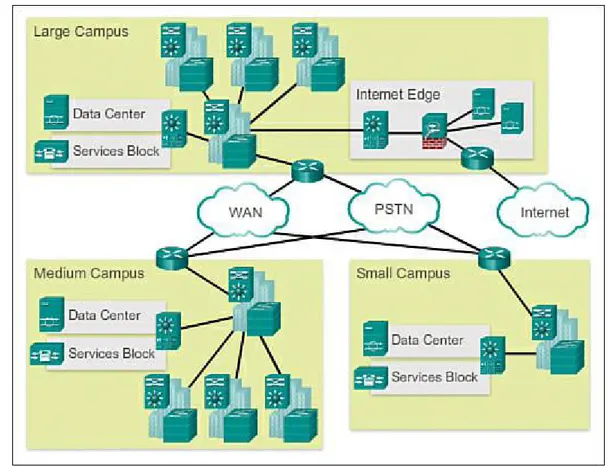
Figure 1-6 shows a three-tier campus network design for organizations where the access,
Figure 1-6 Three-Tier Campus Network Design
In some cases, because of a lack of physical or network scalability restrictions, maintaining a separate distribution and core layer is not required. In smaller campus locations where there are fewer users accessing the network or in campus sites consisting of a single building, separate core and distribution layers may not be needed. In this scenario, the recommendation is the alternate two-tier campus network design, also known as the collapsed core network design.
Figure 1-7 Two-Tier Campus Network Design
Activity 1.1.1.6 Part 1: Identify Switched Network Terminology
This activity is found in the course in the first graphic in 1.1.1.6. Go to the online course to match the term with the switch characteristic.
Activity 1.1.1.6 Part 2: Identify Switched Network Layer Functions
Go to the course online and click on the second graphic. Perform the practice activity by
matching specific characteristics to one of the three layers of the switch network design model.
Switched Networks (1.1.2)
Switched networks are important when deploying wired LANs. A network professional today must be well-versed in switches and LAN technology in order to add commonly deployed devices such as PCs, printers, video cameras, phones, copiers, and scanners. Sharing and accessing network devices is common in both the home and business network.
Role of Switched Networks (1.1.2.1)
The role of switched networks has evolved dramatically in the last two decades. It was not long ago that flat Layer 2 switched networks were the norm. Flat Layer 2 data networks relied on the basic properties of Ethernet and the widespread use of hub repeaters to propagate LAN traffic throughout an organization. As shown in Figure 1-8, networks have fundamentally changed to switched LANs in a hierarchical network. A switched LAN allows more flexibility, traffic management, and additional features, such as:
Quality of service Additional security
Support for wireless networking and connectivity
Figure 1-8 Hierarchical Networks
Figure 1-9 shows the hierarchical design used in the borderless switched network.
Figure 1-9 Three-Tier Design in Borderless Switched Networks Form Factors (1.1.2.2)
There are various types of switches used in business networks. It is important to deploy the
Table 1-1 Business Considerations for Switch Selection
When selecting the type of switch, the network designer must choose between a fixed or a modular configuration, and stackable or non-stackable. Another consideration is the thickness of the switch, which is expressed in number of rack units. This is important for switches that are mounted in a rack. For example, the fixed configuration switches shown in Figure 1-10 are all 1 rack unit (1U). These options are sometimes referred to as switch form factors.
Fixed Configuration Switches
Fixed configuration switches do not support features or options beyond those that originally came with the switch (refer to Figure 1-10). The particular model determines the features and options available. For example, a 24-port gigabit fixed switch cannot support additional ports. There are typically different configuration choices that vary in how many and what types of ports are included with a fixed configuration switch.
Modular Configuration Switches
Modular configuration switches offer more flexibility in their configuration. Modular configuration switches typically come with different sized chassis that allow for the installation of different
numbers of modular line cards (Figure 1-11). The line cards actually contain the ports. The line card fits into the switch chassis the way that expansion cards fit into a PC. The larger the chassis, the more modules it can support. There can be many different chassis sizes to choose from. A modular switch with a 24-port line card supports an additional 24-port line card, to bring the total number of ports up to 48.
Figure 1-11 Modular Configuration Switches Stackable Configuration Switches
Stackable configuration switches can be interconnected using a special cable that provides high-bandwidth throughput between the switches (Figure 1-12). Cisco StackWise technology allows the interconnection of up to nine switches. Switches can be stacked one on top of the other with cables connecting the switches in a daisy chain fashion. The stacked switches effectively operate as a single larger switch. Stackable switches are desirable where fault tolerance and bandwidth availability are critical and a modular switch is too costly to implement. Using cross-connected connections, the network can recover quickly if a single switch fails. Stackable switches use a special port for
Figure 1-12 Stackable Configuration Switches
Activity 1.1.2.3: Identify Switch Hardware
Go to the online course to match the term to the switch selection criteria.
The Switched Environment (1.2)
One of the most exciting functions of networking is the switched environment because businesses are always adding devices to the wired network, and they will do so through a switch. Learning how switches operate is important to someone entering the networking profession.
Frame Forwarding (1.2.1)
On Ethernet networks, frames contain a source MAC address and a destination MAC address. Switches receive a frame from the source device and quickly forward it toward the destination device.
Switching as a General Concept in Networking and Telecommunications (1.2.1.1)
The concept of switching and forwarding frames is universal in networking and telecommunications. Various types of switches are used in LANs, WANs, and the public switched telephone network (PSTN). The fundamental concept of switching refers to a device making a decision based on two criteria:
Ingress port
Destination address
The decision on how a switch forwards traffic is made in relation to the flow of that traffic. The term ingress is used to describe a frame entering a device on a specific port. The term egress is used to describe frames leaving the device through a particular port.
A LAN switch maintains a table that it uses to determine how to forward traffic through the switch.
Activity 1.2.1.1: LAN Switch Forwarding Operation
Go to the course online to see an animation of how a switch forwards a frame based on the destination MAC address. Click the Play button to begin.
In the animated example:
If a message enters switch port 1 and has a destination address of EA, then the switch forwards the traffic out port 4.
If a message enters switch port 5 and has a destination address of EE, then the switch forwards the traffic out port 1.
If a message enters switch port 3 and has a destination address of AB, then the switch forwards the traffic out port 6.
The only intelligence of the LAN switch is its capability to use its table to forward traffic based on the ingress port and the destination address of a message. With a LAN switch, there is only one master switching table that describes a strict association between addresses and ports; therefore, a message with a given destination address always exits the same egress port, regardless of the ingress port it enters.
Cisco LAN switches forward Ethernet frames based on the destination MAC address of the frames. Dynamically Populating a Switch MAC Address Table (1.2.1.2)
Switches use MAC addresses to direct network communications through the switch to the appropriate outbound port toward the destination. A switch is made up of integrated circuits and accompanying software that controls the data paths through the switch. For a switch to know which port to use to transmit a frame, it must first learn which devices exist on each port. As the switch learns the
relationship of ports to devices, it builds a table called a MAC address table, or content addressable memory (CAM) table. CAM is a special type of memory used in high-speed searching applications. LAN switches determine how to handle incoming data frames by maintaining the MAC address table. A switch builds its MAC address table by recording the MAC address of each device connected to each of its ports. The switch uses the information in the MAC address table to send frames destined for a specific device out the port, which has been assigned to that device.
An easy way to remember how a switch operates is the following saying: A switch learns on
“source” and forwards based on “destination.” This means that a switch populates the MAC address table based on source MAC addresses. As frames enter the switch, the switch “learns” the source MAC address of the received frame and adds the MAC address to the MAC address table or refreshes the age timer of an existing MAC address table entry.
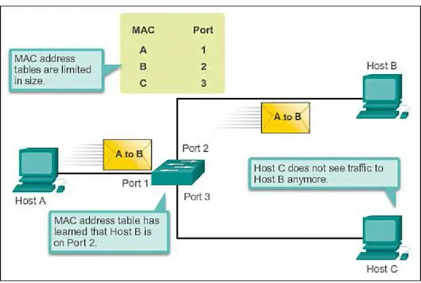
To forward the frame, the switch examines the destination MAC address and compares it to
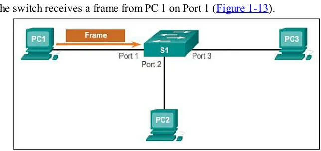
The following steps describe the process of building the MAC address table:
Step 1. The switch receives a frame from PC 1 on Port 1 (Figure 1-13).
Figure 1-13 Building a MAC Address Table: PC1 Sends Frame to Port 1
Step 2. The switch examines the source MAC address and compares it to the MAC address table. If the address is not in the MAC address table, it associates the source MAC address of
PC 1 with the ingress port (Port 1) in the MAC address table (Figure 1-14).
Figure 1-14 Building a MAC Address Table: S1 Adds MAC Address Heard Through Port 1 If the MAC address table already has an entry for that source address, it resets the
aging timer. An entry for a MAC address is typically kept for five minutes.
Step 3. After the switch has recorded the source address information, the switch examines the destination MAC address.
(Figure 1-15).
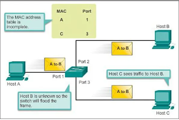
Figure 1-15 Building a MAC Address Table: S1 Broadcasts the Frame
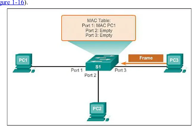
Step 4. The destination device (PC 3) replies to the frame with a unicast frame addressed to PC 1 (Figure 1-16).
Figure 1-16 Building a MAC Address Table: PC3 Sends a Reply Frame
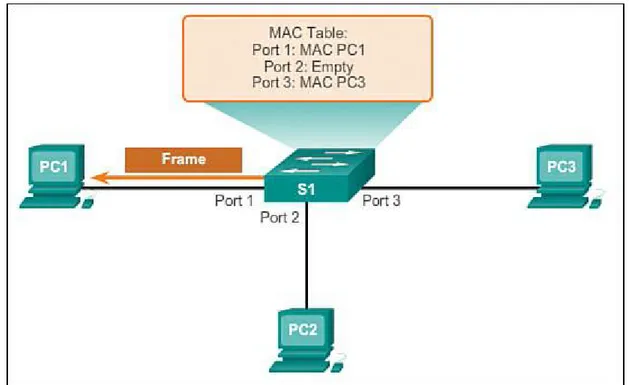
Figure 1-17 Building a MAC Address Table: S1 Adds the MAC Address for PC3
Step 6. The switch can now forward frames between these source and destination devices without flooding because it has entries in the address table that identify the associated ports (Figure 1-18).
Figure 1-18 Building a MAC Address Table: S1 Sends the Frame to Port 1 Switch Forwarding Methods (1.2.1.3)
Commonly, in earlier networks, as they grew, enterprises began to experience slower network
number of ports without degrading performance. This method of forwarding data frames at Layer 2 was referred to as store-and-forward switching. This term distinguished it from cut-through switching.
As shown in the online video, the store-and-forward method makes a forwarding decision on a frame after it has received the entire frame and then checked the frame for errors.
Video 1.2.1.3: Store-and-Forward Switching
Go to the course online to see an animation of how a store-and-forward switch works.
By contrast, the cut-through switching method, as shown in the online video, begins the forwarding process after the destination MAC address of an incoming frame and the egress port has been
determined.
Video 1.2.1.3: Cut-Through Switching
Go to the course online. Click on the second graphic to see an animation of how a cut-through switch works.
Store-and-Forward Switching (1.2.1.4)
Store-and-forward switching has two primary characteristics that distinguish it from cut-through: error checking and automatic buffering.
Error Checking
A switch using store-and-forward switching performs an error check on an incoming frame. After receiving the entire frame on the ingress port, as shown in Figure 1-19, the switch compares the frame-check-sequence (FCS) value in the last field of the datagram against its own FCS
calculations. The FCS is an error checking process that helps to ensure that the frame is free of
Figure 1-19 Store-and-Forward Switching Automatic Buffering
The ingress port buffering process used by store-and-forward switches provides the flexibility to support any mix of Ethernet speeds. For example, handling an incoming frame traveling into a 100 Mb/s Ethernet port that must be sent out a 1 Gb/s interface would require using the store-and-forward method. With any mismatch in speeds between the ingress and egress ports, the switch stores the entire frame in a buffer, computes the FCS check, forwards the frame to the egress port buffer and then sends the frame.
Store-and-forward switching is Cisco’s primary LAN switching method.
A store-and-forward switch drops frames that do not pass the FCS check, therefore it does not forward invalid frames. By contrast, a cut-through switch may forward invalid frames because no FCS check is performed.
Cut-Through Switching (1.2.1.5)
An advantage to cut-through switching is the capability of the switch to start forwarding a frame earlier than store-and-forward switching. There are two primary characteristics of cut-through switching: rapid frame forwarding and invalid frame processing.
Rapid Frame Forwarding
Figure 1-20 Cut-Through Switching
With today’s MAC controllers and ASICs, a switch using the cut-through method can quickly decide whether it needs to examine a larger portion of a frame’s headers for additional filtering purposes. For example, the switch can analyze past the first 14 bytes (the source MAC address, destination MAC, and the EtherType fields), and examine an additional 40 bytes in order to perform more sophisticated functions relative to IPv4 Layers 3 and 4.
The cut-through switching method does not drop most invalid frames. Frames with errors are forwarded to other segments of the network. If there is a high error rate (invalid frames) in the
network, cut-through switching can have a negative impact on bandwidth; thus, clogging up bandwidth with damaged and invalid frames.
Fragment Free
Fragment free switching is a modified form of cut-through switching in which the switch waits for the collision window (64 bytes) to pass before forwarding the frame. This means each frame will be checked into the data field to make sure no fragmentation has occurred. Fragment free mode provides better error checking than cut-through, with practically no increase in latency.
With a lower latency speed advantage of cut-through switching, it is more appropriate for extremely demanding, high-performance computing (HPC) applications that require process-to-process
latencies of 10 microseconds or less.
Activity 1.2.1.6: Frame Forwarding Methods
Activity 1.2.1.7: Switch It!
Go to the course outline to perform this practice activity where you have multiple scenarios of frames going through a switch. Select how the switch will handle the frame.
Switching Domains (1.2.2)
Two commonly misunderstood terms used with switching are collision domains and broadcast domains. This section tries to explain these two important concepts that affect LAN performance. Collision Domains (1.2.2.1)
In hub-based Ethernet segments, network devices compete for the medium, because devices must take turns when transmitting. The network segments that share the same bandwidth between devices are known as collision domains, because when two or more devices within that segment try to
communicate at the same time, collisions may occur.
It is possible, however, to use networking devices such as switches, which operate at the data link layer of the OSI model to divide a network into segments and reduce the number of devices that compete for bandwidth. Each port on a switch is a new segment because the devices plugged into the ports do not compete with each other for bandwidth. The result is that each port represents a new collision domain. More bandwidth is available to the devices on a segment, and collisions in one collision domain do not interfere with the other segments. This is also known as microsegmentation. As shown in the Figure 1-21, each switch port connects to a single PC or server, and each switch port represents a separate collision domain.
Broadcast Domains (1.2.2.2)
Although switches filter most frames based on MAC addresses, they do not filter broadcast frames. For other switches on the LAN to receive broadcast frames, switches must flood these frames out all ports. A collection of interconnected switches forms a single broadcast domain. A network layer device, such as a router, can divide a Layer 2 broadcast domain. Routers are used to segment both collision and broadcast domains.
When a device sends a Layer 2 broadcast, the destination MAC address in the frame is set to all binary ones. A frame with a destination MAC address of all binary ones is received by all devices in the broadcast domain.
The Layer 2 broadcast domain is referred to as the MAC broadcast domain. The MAC broadcast domain consists of all devices on the LAN that receive broadcast frames from a host.
Activity 1.2.2.2: Broadcast Domains
Go to the online curriculum, and click Play to see this in the first half of the animation.
Watch how a switch broadcasts a frame out all ports except the port that received the frame.
When a switch receives a broadcast frame, the switch forwards the frame out each of the switch ports, except the ingress port where the broadcast frame was received. Each device connected to the switch receives a copy of the broadcast frame and processes it, as shown in the top broadcast domain in Figure 1-22. Broadcasts are sometimes necessary for initially locating other devices and network services, but they also reduce network efficiency. Network bandwidth is used to propagate the