Benefit of Channel Availability In An Underground Coal
Gasification Laboratory Scale
Harijanto Soetjijo
aa
Pusat Penelitian Geoteknologi, LIPI, Jl. Sangkuriang Bandung 40135
______________________________________________________________________________________________________________________________ ABSTRAK Keunggulan dari keberadaan alur gasifikasi pada percobaan gasifikasi batubara bawah tanah diselidiki di laboratorium. Percobaan dilakukan dengan menggunakan sebuah reaktor simulasi berbentuk persegi panjang yang terbuat dari besi. Dalam studi ini ada dua percobaan yang dilakukan yaitu: percobaan pertama tanpa adanya alur gasifikasi dan percobaan kedua dengan sebuah alur gasifikasi didalam reaktor. Hasil percobaan menunjukkan bahwa jumlah gas CO2 adalah dalam
kisaran (4,6-11,4)% dan (11,6-14,4)%; gas CO dalam kisaran (0,3-4,0)% dan (1,2-6,8)%; gas H2
dalam kisaran (0,1-2,5)% dan (1,6-3,2)%; gas C3H8 dalam kisaran (0,0-0,6)% dan (0,2-0,9)%; gas
CH4 dalam kisaran (0,0-2,2)% dan (0,4-3,0)%, gas CnHm adalah dalam kisaran 0,0)% dan
(0,0-0,4)% untuk percobaan pertama dan kedua berturut-turut. Nilai kalori gas adalah dalam kisaran (81-343)kcal/m3 dan (263-516)kcal/m3 berturut-turut. Kisaran dari pengembangan temperatur pada saat proses gasifikasi berjalan menunjukkan bahwa pada percobaan pertama, kisaran temperatur gasifikasi T1 pada adalah (335-565)oC; dan T2 adalah dalam kisaran (110-240)oC. Dilain pihak, T1
untuk percobaan kedua adalah dalam kisaran (550-705)oC dan T2 dalam kisaran (160-628)oC. Selain
itu pada percobaan pertama, pola perubahan temperatur T1 dan T2 mempunyai kecenderungan
menurun, sedangkan pada percobaan kedua, pola temperatur T1 dan T2 tersebut mempunyai
kecenderungan meninggi seiring dengan jalannya proses gasifikasi. Hal ini dapat disimpulkan bahwa adanya alur gasifikasi pada percobaan kedua memungkinkan reaksi-reaksi gasifikasi berjalan lebih efisien dibandingkan dengan reaksi-reaksi yang terjadi pada percobaan pertama tanpa alur didalamnya.
Kata Kunci : Gasifikasi bawah tanah, batubara, alur, reaktor, komposisi gas
______________________________________________________________________________________________________________________________ ABSTRACT The benefit of gasification channel availability in an underground coal gasification experiment is investigated in laboratory. The experiment is conducted using a simulation rectangular reactor made of steel. There are two experiments conducted in this study: the first experiment is without gasification channel and the second experiment with a gasification channel inside the reactor. The result of the experiments shows that the amount of CO2 gas is in the range of (4,6-11,4)% and (11,6-14,4)%; CO gas is in the range of (0,3-4,0)% and (1,2-6,8)%; H2 gas is in the range of (0,1-2,5)% and (1,6-3,2)%; C3H8 gas is in the range of (0,0-0,6)% and (0,2-0,9)%; CH4 gas in the range of (0,0-2,2)% and (0,4-3,0)%, CnHm gas in the range of (0,0-0,0)% and (0,0-0,4)% for the first and the second experiment respectively. The caloric value of gas is in the range of (81-343)kcal/m3 and (263-516)kcal/m3 respectively. The range of temperature development during the gasification process shows that: in the first experiment, the range of gasification temperature T1 is (335-565)oC; and T2 is in the range of (110-240)oC. On the other hand, T1 from the second experiment is in the range of (550-705)oC and T2 is in the range of (160-628)oC. Besides that in the first experiment, the pattern of T1 dan T2 changing has a decreasing tendency, while in the second experiment, it has an increasing tendency in relation with the progress of gasification process. It can be concluded that the availability of gasification channel in the second experiment allows the gasification reactions occur more efficiently compared with the reactions in the first experiment without the channel inside.
______________________________________________________________________________________________________________________________
INTRODUCTION
Underground coal gasification is not a new idea, it was first suggested by Siemens in 1868 for the gasification of coal left in place after mining. Underground coal gasification is a method of converting unworked coal, deep underground, into a combustible gas, which can be used for industrial heating, power generation or the manufacture of hydrogen, synthetic natural gas or other chemicals.
Basically, this method allows us to eliminate the need for mining especially for the coal which is considered uneconomical to mine, due to several reasons for example the coal seam which locates very deep underground. Edgar (1974) mentioned that this underground coal gasification method was the most economical method to convert the solid coal to gas. Besides that, this method is able to reduce the risk of mining and minimize the environmental destruction related with the mining activities (Schrider & Whieldon, 1977).
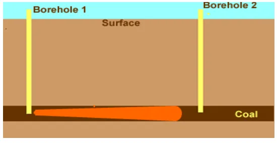
The basic concept of underground coal gasification is illustrated in Figure 1. Two boreholes, or wells, are drilled to the bottom of the coal seam to be gasified. Normally the natural permeability of the coal bed is not high enough nor the fissures large enough to permit gas percolation through the seam, so it is necessary to enhance the permeability. This is called “linking” of the wells or in other word it can be mentioned as the gasification channel forming, in which narrow linear channel of high permeablity are formed without increasing the permeablity of the bulk of the coal seam. There are three parameters affects the underground gasification process. The first parameter is the geological parameter such as coal seam thickness, type of overburden; country rocks; and water table. The second group of parameters is the characteristics of coal such as moisture and ash contents; caking ability etc. The third group is the operasional parameters of gasification such as airflow rate; gasification channel; oxygen rate, pressure, the length of gasification zone etc. The knowledge and understanding of those parameters are very important and very helpful in planning the equipments related with the operation and interpretation of the result of underground coal gasification.The geological parameters and characteristics of coal are the most important and closely related. The operasional parameters are used to eliminate or at least to reduce the negative effect of geological parameter and characteristics of coal in this underground coal gasification. The effective combination of these parameters can support the successive progress of an underground coal gasification either from quantity or quality of gas product or from the efficiency point of view of this gasification process (Gunn, 1978).
Figure 1. Basic concept of an undergrund coal gasification.
need of energy in the future, a study to provide a clean and covenient source of energy from coal seams where tradional mining methods are either impossible or uneconomical is proposed in Research Centre of Geotechnology. An experimental study in laboratory using a simulation underground coal gasification reactor is conducted. According to Thomas (1978) and Thorness G.B., et al. (1978), a simulation reactor has to be designed to cover as many as all the parameters which are considered will affect the gasification process.
In this paper, the result of an experiment of underground coal gasification using a simulation reactor and the effect of the availability of a gasification channel to the gas composition and process will be discussed.
MATERIAL AND METHODS
Underground gasification reactor
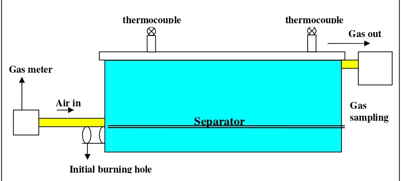
In this study, a simulation reactor which designed to cover almost all the conditions of underground coal gasification is used. This rectangular reactor is made from steel plate with 2 mm thickness. The length of the reactor is 80 cm, width is 30 cm and height is 20 cm. The reactor has an initial iginition hole; air input hole; and a gas output hole. The reactor is completed with two thermocouples, located 25 cm from its edges. The reactor is put in a wood box (120 X 80 X 50 cm) and covered with clay and soil to prevent heat loss during the gasification process. There is a temporary plate made of tabular pipe steel which can be used to separate the room inside the reactor. This plate is put about 4 cm from the base of reactor and arranged in a manner so that there is a channel in the lower part of reactor. This separator is used to form a gasification channel inside the reactor. This separator plate is used for the second experiment but the plate is not used in the first experiment. Figure 2 represents the basic design of the reactor.
Gas sampling Gas meter
Initial burning hole Air in
Gas out
Separator
thermocouple thermocouple
Figure 2: The basic design of simulation underground coal gasification reactor.
Compressor
Gas meter
A gas meter is used to measure the volume of air input flowing to the reactor during the experiment.
Coal
Coal used in the experiment is obtained from Widodaren, Rembang, Middle of Java. The size of coal used in the process is –3 cm. The composition of Widodaren coal is as followed: Moisture content = 10,08%; ash content = 3,83%; volatile matter content = 31,51% dan fixed carbon content = 54,48%.
Procedure
Coal with size –3 cm diameter is filled into the reactor. The reactor is then put in a wooden box and covered with clay and soil. The gasification is started with the initial ignition using a burner. The initial ignition is set for two hours and after the coal starts to burn itself, the air from the compressor is blowed to the reactor through the air input hole. Air flow from the compressor is arranged using a gas meter. In this experiment, the air flow is set at 70 litres per minute.
There are two experiment conducted.
In the first experiment, coal fills all part of reactor so that there is no gasification channel inside. The burning of coal will start from the bottom of the reactor from where the gasification occurs and the propagation of gasification runs freely. Consequently the ash will set down naturally so that some of coal remains unburn due to the ash covering the coal.
On the other hand, in the second experiment the coal only fills the upper part of reactor because the separator is set in the reactor so that there is a empty room (channel) in the bottom of reactor. Due to this arrangement the initial burning starts on the layer of coal laid about 4 cm from the bottom of reactor. As the gasification is in progress and ash as the byproduct of the process will set down into this empty part. The gasification occurs without any interference and no unburned coal due to the ash falling down covering the coal as happened in the first experiment without gasification channel inside.
Length of experiment
The gasification experiment is conducted for 16 hours totally. The initial ignition is 2 hours, and the gasification runs for 14 hours.
Gas sampling
Gas from the experiment is sampled using a gas sampling tube (length is 30 cm and diameter is 5 cm) made from glass. The gas sampling is done using the gravitation method. The gas sampling is done every hour during the course of the gasification process so that there is 14 gas samples for one experiment in each reactor.
Gas analysis
RESULTS AND DISCUSSION
There are two experiments conducted in this study. The result obtains from the first experiment is summarized in Table 1. The result of the second experiment conducted with a gasification channel inside is summarized in Table 2.
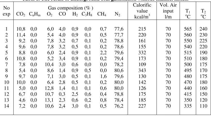
The result of the first gasification experiment conducted using the reactor without gasification channel inside shows that (see Table 1):
The content of gas CO2 is (4,6-11,4)%; gas CnHm is (0,0-0,0)%; gas O2 is (4,6-11,4)%; gas CO is (0,3-4,0)%; gas H2 is (0,1-2,5)%; gas C3H8 is (0,0-0,6)%; gas CH4 is (0,0-2,2)%; gas N2 is (76,2-81,0)%. The calorific value of gas is (81-343) kcal/m3.
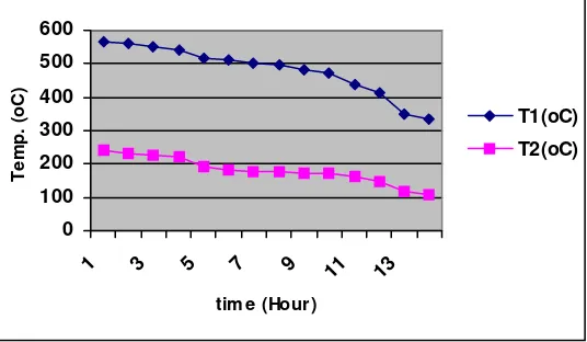
The range of temperature during the experiment is: T1 = (335-565)oC; and T2 = (110-240)oC.
Tabel 1. The result of underground coal gasification without channel inside.
No
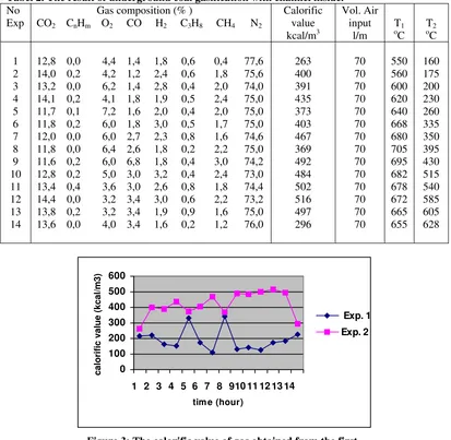
On the other hand, the second gasification experiment conducted in the reactor with gasification channel inside shows that (see Table 2):
The content of gas CO2 is (11,6-14,4)%; gas CnHm is (0,0-0,4)%; gas O2 is (3,2-7,2)%; gas CO is (1,2-6,8)%; gas H2 is (1,6-3,2)%; gas C3H8 is (0,2-0,9)%; gas CH4 is (0,4-3,0)%; gas N2 is (73,0-77,6)%. The calorific value of gas is (263-516) ) kcal/m3.
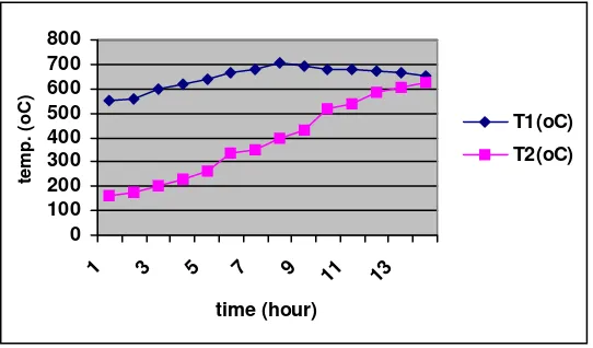
The range of temperature during the experiment is: T1 = (550-705)oC; and T2 = (160-628)oC.
Tabel 2. The result of underground coal gasification with channel inside.
Figure 3: The calorific value of gas obtained from the first and second experiment.
ash covers the coal so that there is no inhibition in gasification progress so that most of the coal burns completely and gasification is propagates in the right manner.
This condition is also supported by temperature observation obtains from both experiments. The gasification temperature in the first experiment is as follows: T1 is in the range of (335-565)oC; and T2 is in the range of (110-240)oC. On the other hand, temperature in the second experiment is as follows: T1 is in the range of (550-705)oC; and T2 in the range of (160-628)oC. These data indicate that the temperature T1 dan T2 measured from the second experiment is higher than T1 dan T2 from the first experiment.
Besides that, the pattern of temperature changing during the course of gasification in the first experiment is quite different with the pattern of temperature changing occurred in the second experiment. Based on the observation of temperature obtains from the first experiment, the pattern of T1 has a decreasing tendency during the gasification progressing. The same pattern also occurres for T2 (see Figure 4). On the other hand, the pattern of temperature T1 and T2 obtained from the second experiment have a different tendency compared with pattern of T1 and T2 from the first experiment. The pattern of T1 and T2 in the second experiment has an increasing tendency in relation with the course and time period of the experiment (see Figure 5).
These differences show that the condition occurres in both experiments or reactors are not same. In the first experiment, after the initial coal burning, the gasification occurs in the bottom of reactor and the coal above falls into the void and also the ash due to the gravitation effect. This condition is unfavourable for the process and consequently some part of coal goes unburn, so that there is a heat loss and it affects the gasification temperature. The temperature along the seam is not high enough to maintain the reactions and as the result the progress of the gasification is not optimum.
Figure 4: The pattern of temperature obtained from the first experiment (conducted without channel inside the reactor)
0 100 200 300 400 500 600
1 3 5 7 9 11 13
tim e (Hour)
Temp. (oC)
T1(oC)
T2(oC)
preparation of a gasification channel is important because the availability of the channel or linking can distinguish the gases produces from the gasification. The channel gasification or the linking is the main element and becomes rate limiting.
Figure 5: The pattern of temperature obtained from the second experiment (conducted with channel inside the reactor)
0 100 200 300 400 500 600 700 800
1 3 5 7 9 11 13
time (hour)
temp. (oC)
T1(oC)
T2(oC)
In this experiment, the calorific value of gas product is (81-343) kcal/NM3 for the gases from the first experiment and (263-516)kcal/NM3 for the gases from the second experiment. This value is regarded as reasonable figure because the injected gas used in this experiment is air. The product gas is dependent on whether air, oxygen, or a steam/oxygen mixture is injected and there are numerous other factors can affect the product gas such as coal type, seam thickness, gas input volume, type of gas input etc. (Probstein & Hicks, 1982) and also the availability of gasification channel as shown by this experiment.
CONCLUSIONS
The result of the experiment show that in an underground coal gasification conducted in laboratory using a simulation reactor, a gasification channel is a rate limiting factor. This gasification channel affects the production of gases and also its quality. The result shows that the first reactor without a channel inside produces less amount of gases (CO2; CnHm; CO; H2; C3H8 and CH4 ) compared the gases from the second reactor which has a channel inside. The gasification process in the first experiment is not as effective as the gasification process in the second experiment. It is indicated by the calorific value of product gas from the first experiment which is in the range of (81-343)kcal/NM3, while the calorific value of gas from the second experiment is in the range of (263-516)kcal/NM3.
It can be concluded that the success of the underground coal gasification depends on the gasification channel foming during the run of the gasification. The channel gasification is one of the main parameter and becomes rate limiting factor in this underground coal gasification although there are numerous other factors can affect the gasification process such as coal type, seam thickness, gas input volume, type of gas input etc. Further experiment is suggested to examine the effect of these other factors to the gasification.
REFERENCES
Armitage,M., and Green, M.B., 2001, Underground Coal Gasification in the United Kingdom, 18th International Pittsburgh Coal Conference, December 2001, Newcastle, Australia.
Dinsmoor, B., et al., 1978, The Modelling Cavity Formation During Underground Coal Gaification, Journal Of Petroleum Technology, Vol.,XXX, May 1978, p. 695-703.
Edgar, T.F., 1974, The Potential of Insitu Coal Gaification in The South West United State. Paper Presented at Project Independence Hearings, Houston, Texas, Sept.18, 1974.
Gunn, R.D., et al, 1978, A Permeation Theory For Insitu Coal Gasification, Society of Petroleum Engineers Journal, October 1978, hal. 300-314.
Probstein, R.F., Hicks R.E., 1982, Synthetic Fuels, International Student Edition, McGraw-Hill Inc, p.207.
Schrider, L.A., Whieldon, C.E., 1977, Underground Coal Gasification, A Status Report, Journal Of Petroleum Technology, vol.,29, Sept. 1977, p. 1179-1185.
Skafa, P.V., 1960. Underground Gasification of Coal, UCRL-Trans-10880, Moscow.
Thorness, G.B., et al., 1978, Insitu Caol Gasification, Model Calculationa and Laboratory Experiments, Society of Petroleum Engineers Journal, April 1978, hal. 105-116.
Wieber D.H., Sikri, A.P., 1978, The Development Of Insitu Process For Energy And Fuels From Coal, Mining Engineering, vol.,30, no. 5, p. 557-563.