MEDIUM-FORMAT CAMERAS AND THEIR USE IN TOPOGRAPHIC MAPPING
Joachim Höhle
Aalborg University, Dept. of Planning, Fibigerstraede 11, 9220 Aalborg, Denmark - [email protected] Commission IV, WG IV/3
KEY WORDS: Camera, Imagery, Performance, Impact Analysis, Application, DEM/DTM, Orthoimage, Updating
ABSTRACT:
Based on practical experiences with large-format aerial cameras the impact of new medium-format digital cameras on topographic mapping tasks is discussed. Two new medium-format cameras are investigated with respect to elevation accuracy, area coverage and image quality. The produced graphs and tables show the potential of these cameras for general mapping tasks. Special attention is given to the image quality of the selected cameras. Applications for the medium-format cameras are discussed. The necessary tools for selected applications are described. The impact of sensors for georeferencing, multi-spectral images, and new matching algo-rithms is also dealt with. Practical investigations are carried out for the production of digital elevation models. A comparison with large-format frame cameras is carried out. It is concluded that the medium-format cameras have a potential for mapping of smaller areas and will be used in future in true orthoimage production, corridor mapping, and updating of maps. Their small dimensions and low weight allow installation in small airplanes, helicopters, and high-end UAVs. The two investigated medium-format cameras are low-cost alternatives for standard mapping tasks and special applications. The detection of changes in topographic databases and DTMs can be carried out by means of those medium-format cameras which can image the same area in four bands of the visible and invisible spectrum of light. Medium-format cameras will play an important role in future mapping tasks.
1. INTRODUCTION
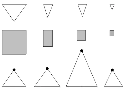
Mapping of topographic features has changed with the upcom-ing of digital aerial cameras. It has become fully digital and to a high extent automatic. High demands of the users of topograph-ic databases, orthoimages, and digital terrain models have to be met. The mapping industry is challenged by low prices of these products and short production times. The instrument making in-dustry has improved the tools and considerable progress has been achieved in the last 10 years. The cameras, for example, became small and compact, but the amount of pixels per frame became higher and higher. Figure 1 depicts this progress. Fea-tures for the film-based wide angle camera, the digital large-format frame camera of the first generation, and the digital large-format camera of the second generation of one manufac-turer are shown graphically. In addition, the latest medium-format digital frame camera is presented. Images of the medi-um-format cameras have a format of 54 mm x 40 mm and be-tween 60 and 80 million pixels (MP) per frame. They have spe-cial solutions for generation of colour images and compensation of image motion. In first applications, the medium-format cam-eras were used in combination with laser scanners where the imagery helped to interpret the laser point clouds. Many other applications are possible and were also carried out. An intro-duction and overview of medium-format cameras is given by (Grenzdörffer, 2010). The recent announcement of two new medium-format cameras with advanced features and new auxil-iary equipment as well as of new processing tools started this investigation. It is the goal of this paper to redefine the potential of medium-format cameras for topographic mapping using up-to-date cameras. The conclusion will be based on practical work with imagery of a test flight and the use of its imagery in stand-ard topographic mapping and some other applications. A com-parison between large-format and medium-format cameras is al-so a goal of this paper.
Figure 1. Features of aerial frame cameras. The symbols mean: Columns from left to right: Film-based wide-angle camera, digi-tal format frame camera of first generation, digidigi-tal large-format camera of second generation, and latest medium-large-format digital frame camera. Rows from top to bottom: Field of view (FOV) in the direction of flight, area of the output image, and flying height for the same ground sampling distance together with FOV across the direction of flight and swath width.
2. NEW CAMERAS OF THE MEDIUM FORMAT
The lately announced medium-format cameras are the Leica RCD30 and the Trimble TAC 80. They are described in detail in (Wagner, 2011) and (Trimble, 2011).
bands and the NIR band are co-registered and corrected for ge-ometric and radige-ometric errors in post-processing. The colour depth is 8 or 16 bit. Two lenses with f=50mm and f=80mm can be interchanged. Both lenses have a central shutter with auto-matically controlled aperture. The maximum frame rate is about one frame per second. The RCD30 can be used as a standalone camera system or in combination with laser scanners.
The Trimble TAC 80MP camera can be equipped with several lenses and sensors. The 80MP version has a small pixel size of 5.2 µm x 5.2 µm. Colour or false colour images can be taken but not at the same time. False color photography requires an-other lens/sensor/filter combination. The colour depth is 16 bit per color. The camera uses a PC for recording of data. The 60MP-version (aka. P65+47mm) has the same format but a larger pixel (6 µm x 6 µm). The applied lenses have a relatively high distortion which can be corrected in the photogrammetric processing by using parameters determined in a calibration. The same is true for deviations of the principal point from the mid-dle of the censor.
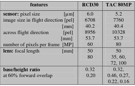
Table 1 summarizes the features of the two medium-format cameras. The image size and the base/height ratio for the 50 mm lens is the same for both cameras. The TAC 80MP has a smaller pixel. By means of these design parameters some performance parameters for mapping can be estimated.
features RCD30 TAC 80MP
sensor: pixel size [µm] image size in flight direction [pel] [mm] across flight direction [pel] [mm] number of pixels per frame [MP]
6.0 Table 1. Features of two new medium-format aerial cameras
3. PERFORMANCE PARAMETERS OF THE TWO NEW MEDIUM-FORMAT CAMERAS
Important performance parameters of a camera system are area coverage, elevation accuracy, and image quality.
3.1 Area coverage
In most of the mapping projects a certain ground sampling dis-tance (GSD) is specified. When GSD=10 cm and lenses with f=50 mm are chosen, the area coverage can be calculated (cf. Table 2). The image size across the flight direction on the ground (aka. swath width) determines the number of flight lines in large area projects. It is a factor of economy. The TAC 80MP has a 1.3 times larger area coverage than the RCD30. In com-parison with large-format cameras the smaller format of the me-dium-format camera is its biggest drawback (cf. Figure 2). For example, the new large-format UltraCam-Eagle of Mi-crosoft/Vexcel, described in (Gruber et al., 2011), has a 1.94
times bigger swath width than the TAC 80MP when the same GSD has to be achieved. Table 2. Flying height, image size and foot print at GSD=10cm
Figure 2. Comparison between large-format and medium-format cameras. At the same FOV and image scale (GSD) the medium-format camera has a much smaller swath width.
3.2 Elevation accuracy
The potential with regard to the elevation accuracy is of great importance for production of digital surface and terrain models. By means of the design parameters of the cameras the elevation accuracy can be estimated by equations 1 and 2.
GSD
The parallax accuracy (σpx’) can be derived from practical tests. The DEM generation by means of different digital large-format cameras revealed an average value of σpx’=0.5 pixel (Höhle, 2011). It is assumed that the value can also be applied for the new medium-format cameras. In this way, all digital aerial cam-eras can be compared on the basis of their design parameters (base/height ratio, pixel size).
and absolute elevation accuracy based on the design parameters of the camera and the assumed parallax accuracy of 0.5 pixels.
camera relative accuracy (σh /h) [‰ of flying height]
absolute accuracy (σh) [GSD] TAC 80MP
(f=50mm)
0.16 1.55
RCD30 (f=50mm)
0.19 1.55
DMC 0.16 1.63
DMCII-250 0.09 1.71
Table 3. Elevation accuracy of digital aerial frame cameras at 60% forward overlap and parallax accuracy of σpx’=0.5 pixels From Table 3 it can be read that both medium-format cameras may automatically derive elevations with an accuracy of σh =1.55∙GSD corresponding to 15.5 cm at GSD=10 cm. This is a better absolute elevation accuracy than with the large-format cameras. If the elevation accuracy is related to the flying height then the relative accuracy of the new DMCII-250 camera ex-ceeds both medium-format cameras. This theoretical considera-tion on the basis of the design parameters of the cameras has to be proven in practical tests of DEM generation. The quality of the images will have influence on the parallax accuracy. 3.3 Image quality
Good image quality requires first of all a good lens. Several pa-rameters have to be considered. The resolving power (R) of the lens, measured in line pairs per millimetre (lp/mm), has to be as high as
R=1000/(2∙pel) (3)
where pel=distance between two pixels, in [µm].
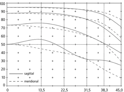
This value is also known as Nyquist frequency. The camera should therefore be equipped with a lens that has such a resolv-ing power (DIN, 2007). In the case of the investigated cameras the required resolution is 83 lp/mm (RCD30) and 96 lp/mm (TAC 80MP), respectively. The lenses of digital cameras are checked by the producers in the laboratory by determining the Modulation Transfer Function (MTF). For different radii the modulation (contrast) of different input frequency (lp/mm) is determined in percent (cf. Figure 3). A typical requirement for lenses used in aerial photography is a contrast in excess of 40% at half of the Nyquist frequency and contrast values below 40% at frequencies twice the Nyquist frequency (Doering et al., 2009). Changes in temperature and pressure may change the performance of the lens if no precautions are carried out by the manufacturer. Other influences on the image quality are the condition of the atmosphere and the proper exposure. Both me-dium-format cameras can be equipped with different lenses in order to meet the requirements of different applications. The in-terchanging of the lenses should maintain the interior orienta-tion. Lenses of the two cameras are for example the Leica NAG-D 50 and the Rodenstock HR NAG-Digaron-W 50, respectively. Both lenses have a focal length of f=50mm, a maximum aperture of f/4 and 1/1000 of a second as shortest exposure time. The Leica lens is thermal stabilized. In addition, lens distortion, displace-ment of the principal point, and light fall-off of the lens are compensated in post processing. Both cameras use Bayer arrays for generation of color images and compensate mechanically for
image motion. The Leica RCD 30 is able to correct in two di-rections. This may be of advantage at strong lateral wind result-ing in deviation of the airplane axis from the flyresult-ing direction.
Figure 3. MTF of Rodenstock HR Digaron-W 50mm f/4 lens for aperture 5.6. The curves represent the 80, 40, 20 and 10 lp/mm frequencies. Source: (Rodenstock, 2011)
3.4 Other features of the two medium-format cameras
Both cameras are compact and of low weight. Such features en-able the use in small airplanes, helicopters and high-end Un-manned Aerial Vehicles (UAVs). Installation in an external pod avoids expensive modifications of the vehicle. An overview on UAVs is given by (Everaerts, 2009). Furthermore, these camer-as are prepared to meet the environmental conditions in higher altitudes. Other features are high frame rates, a gyro-stabilized mount, and position and attitude measuring devices (GNSS/IMU). The combination with a laser scanner opens up for other applications and performances. In comparison with the large-format cameras the price is much lower. The operational costs, however, become higher when large areas have to be mapped. The number of strips to be flown and thereby the length of flight will increase. In the example of Figure 2 the flight with the medium-format camera (TAC-80) is 1.94 times longer than with the large-format camera (UltraCam-Eagle). The costs of flying will increase about by the same factor.
4. SOME MAPPING TASKS
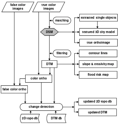
geomet-ric and radiometgeomet-ric resolution. The generation of digital terrain models (DTMs) needs also efficient filtering of the matched points. All processing should be carried out with a high degree of automation and reliability. Medium-format cameras may also find application in remote sensing tasks like classification of land cover. There will also be new mapping tasks, e.g. the gen-eration of digital surface models, 3D city models, true or-thoimages, false-colour oror-thoimages, slope and erosivity maps, and flood risk maps. Also the updating of 2D topographic data bases and DTMs can take advantage of medium-format cameras because the areas to be mapped are often small. The involved processes (matching, filtering and change detection) require fea-tures which the new generation of medium-format cameras and new software tools can fulfil. Figure 4 depicts a generalized flow chart how such products could be produced.
Figure 4. New mapping products and their generation
5. PRACTICAL INVESTIGATIONS
Practical investigations are carried out with image material of the new Leica RCD30 camera. The image data are first de-scribed and then used in a few of the above dede-scribed new ap-plications. The new tools applied in the different applications are mentioned.
5.1 Used imagery and its quality
Multispectral images consisting of four bands (RGBN) were taken with the Leica RCD30 camera equipped with the NAG-D 3.5/50 lens in June 2011. Several strips with GSD=5 cm were flown with about 75% end lap and 30% side lap. The photo-graphed area contained buildings and vegetation near a small town in Switzerland. The images have small tilts (< 0.2 °) thanks to the used gyro-stabilized mount. The drift angle is rela-tively high (about 17 °) which will challenge the forward mo-tion compensamo-tion (FMC) of the camera. The calibramo-tion report informs that the calibrated focal length is f=53.00 mm and that distortion and other geometric errors have been removed. The provided images are also corrected for Dark Signal Non-Uniformity (DSNU) and Photo Response Non Non-Uniformity (PRNU). The orientation data of the images were derived in an aerotriangulation using a few ground control points (GCPs). Image quality may be checked also by the user. For example, the width of stripes on roads may be measured to determine the so-called blooming of the sensor. When big differences between
the widths of bright stripes and dark spaces (a-b) are found, the anti-blooming devices of the sensor may not work properly. Such effect will displace the position of objects with high con-trast. Furthermore, the PRNU may be tested at objects in differ-ent image positions. Light fall-off of the lens and non-uniform pixel sensitivity may be discovered then. The PRNU influences the results of classifications.
Figure 5. Stripes on roads at different image parts may be used to check for blooming and PRNU
Tests with the RCD30 camera showed satisfying results (cf. Ta-ble 4). The measured intensity values are equal in the middle and the edge of the image; the differences between the stripes and spaces were 2.6 and 2.2 pixels respectively. The displace-ment (c) is only a quarter of these values. At images with GSD=5 cm the edge of a stripe is then shifted by about 3 cm. The end of bright stripes on dark roads should therefore not be used as GCP. The condition of this PRNU test, that the actual widths have to be equal in size, was not verified in the field.
image
Table 4. Checking of RCD30 images for PRNU and blooming 5.2 Applications
The applications dealt with are DSM generation, building gen-eration, production of true and false-colour orthoimages, and updating of 2D topographic databases and DTMs.
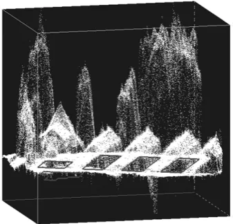
5.2.1 DSM generation: The digital surface models are of in-terest to the mapping industry because they are the prerequisite for the automated extraction of buildings, bridges, etc. Several new tools were created, e.g. the release 5.4 of Trimble/Inpho’s Match-T program. The new features of this program are genera-tion of a very dense point cloud, short processing times, support of large data sets, and distributed processing (Heuchel et al., 2011). In general, the matching of images with poor texture may lead to blunders and inaccuracies of the derived elevations. High image quality and high dynamic range can avoid or reduce these deficiencies. Figure 6 shows a point cloud derived from RCD30 images and using the new software tool Match-T 5.4. The distance between DSM posts is 0.25 m only. Independent and many check points are necessary in order to determine the absolute elevation accuracy of the test. The elevation accuracy has been checked by means of a few GCPs and resulted in σh=0.04 m and RMSEh=0.22 m. A very dense and positional correct DSM can also be the base for line mapping of modest
planimetric accuracy. Such an automated approach may replace the current manual mapping technology. However, some manu-al editing work will still be necessary.
Figure 6. Profile data of DSM result
5.2.2 Building generation: The production of 3D building models is a rather new task for the mapping industry. They are produced with different levels of detail (LOD). Simplest is the wire frame model (LOD1); more complex are building models with generalized roof shapes (LOD2) or with additional tex-tured facades (LOD3).
Advanced tools for the generation of buildings are at disposal, e.g. the “BuildingGenerator” of Trimble/Inpho, which starts from a georeferenced point cloud for modelling the roofs. In addition, a DTM and 2D data of buildings (footprints) are re-quired, in order to generate building models of the LOD2 type. Ridge lines are generated by intersecting segmented tilted planes. Lifting the footprint up to the modelled roof then creates the building model. The modelling of buildings can to a large extent be carried out automatically. The footprint may be gener-alized and various roof types (flat, saddle back, hip, mansard, crippled hip, and tent roof) can be created. Several parameters have to be specified including the required quality in modelling. More details are described in the manual of the “BuildingGen-erator” (Trimble/Inpho, 2009). The use of a 3D-editor in com-bination with a database is of advantage. Figure 7 depicts a wire frame model of houses which were derived semi-automatically. 5.2.3 Production of true orthoimages: Orthoimages are usual-ly produced by means of a digital terrain model. In standard or-thoimages the objects above the terrain are displaced and details near the elevated objects are hidden. True orthoimages avoid these problems and should therefore be produced for urban are-as. A prerequisite for the production of true ortho-images are images of large forward and lateral overlap. The orthoimage can then be generated from several images and details near build-ings are contained in the orthoimage. Building facades will be invisible in the true orthoimage (cf. Figure 8).
5.2.4 Production of false-colour orthoimages: The generation of false-colour orthoimages is easily to accomplish from images of a multi-spectral camera using co-registration of the NIR band with the RGB bands. The same orientation and DTM can be ap-plied. The generation of the DTM from the point clouds re-quires filtering so that only elevations representing the bare earth will remain. It also includes the removal of blunders. This process is to a large extent carried out automatically. The gaps
have to be filled again with points by means of interpolation us-ing surroundus-ing points. The produced DTM is a base for other applications such as derivation of contour lines, slope and ero-sivity maps, and maps for flood risks (cf. Figure 4).
Figure 7. Building model. The building roofs were extracted from a very dense point cloud generated from RCD30 imagery.
Figure 8. Building and vector plot in orthoimage (left) and true orthoimage (right).
A false-colour orthoimage is a prerequisite for other products based on remote sensing techniques, e.g. applying the normal-ized difference vegetation index (NDVI) allows separating be-tween vegetation and non-vegetation (cf. Figure 9). More ad-vanced software use elevation and vegetation data in order to separate trees, vegetated ground and non-vegetated ground. 5.2.5 Updating of 2D topographic databases and DTMs: An important task for mapping organizations is the updating of topographic databases. The detection of changes in the land-scape is a key process. The combined use of elevation and vege-tation maps will assist to detect new or missing buildings. The use of false-colour orthoimages and DSMs for updating of topographic 2D databases has been demonstrated in (Champion, 2009). The use of a digital aerial camera which records four bands simultaneously is a very useful tool for such a task.
The updating of DTMs can be carried out by means of overlap-ping orthoimages. If the elevation model used in the generation of the orthoimages had errors they would show up as parallaxes between the two orthoimages. The parallaxes can automatically be measured and converted into elevation differences. Details on this automated approach of DTM correction has been pub-lished in (Höhle and Potuckova, 2006).
6. DISCUSSION
The ground coverage of the output image of the two considered medium-format cameras is about four times smaller than the coverage of a large-format digital frame camera at the same ground sampling distance. The smaller format results also in lower relative elevation accuracy. This drawback may be com-pensated due to higher geometric accuracy of the one-chip solu-tion, which still has to be proven in test field calibrations. Other fundamental differences between medium-and large-format digital frame cameras are in the generation of colour and in im-age motion compensation. The used lenses should be adapted to the resolution of the sensor. Advantageous for medium-format cameras is low weight, compactness, and price. Also the flexi-bility due to exchangeable lenses and smaller amount of data per image are advantages at special applications. The use of medium-format cameras is especially suitable for small-area projects which exist in corridor mapping, generation of city models, and updating of topographic databases. The presented applications may use a medium-format camera; and together with advanced processing tools new products like DSMs, true orthoimages, and 3D building models can be generated nearly automatically. More practical work with medium-format camer-as is necessary in order to prove these findings.
7. CONCLUSIONS
Advanced medium-format cameras may produce imagery of good quality. Tests with the RCD30 camera revealed uniform photo response and small blooming at edges of high contrast. Mapping tasks such as orthoimage production and stereo com-pilation can be carried out accurately and reliably. Digital sur-face models can be produced with a high density and good ver-tical accuracy. The automaver-tically generated DSM is the prerequisite for several new applications. Medium-format cam-eras with co-registration of a near-infrared image and radio-metric calibration of all sensors will find new applications in remote sensing tasks. Medium-format cameras are smaller and more compact and can therefore be installed in small airplanes, helicopters, and high-end UAVs. They have a lower price and very likely also smaller operational costs than the large-format cameras. The user of medium-format cameras will therefore have a better competitive position in getting mapping contracts. The medium-format cameras will especially be used in small ar-ea projects such as mapping of narrow corridors, generation of city models, and updating of topographic databases and DTMs.
REFERENCES
Champion, N., 2009. Detection of unregistered buildings for updating 2D databases. EuroSDR Official Publication, no. 56, pp. 7-54.
DIN, 2007. DIN 18740-4 - Photogrammetric products- part 4: Requirements for digital aerial cameras and digital aerial photo-graphs, Berlin, September 2007.
Doering, D., Hildebrandt, J., Diete, N., 2009. Advantages of Customized Optical Design for Aerial Survey Cameras. In: Fritsch, D. (Ed.), Photogrammetric Week’09, Wichmann Ver-lag, pp. 69-80.
Everaerts, J.,2009. Unconventional Platforms (Unmanned Air-craft Systems) for Remote Sensing, In: EuroSDR Official Publi-cation no. 56, pp.57-98.
Grenzdörffer, G., 2010. Medium-format cameras. In: EuroSDR Official Publication, no. 58, pp. 233-262.
Gruber, M., Ponticelli, M., and Wiechert, A., 2011. UltraCam, a brand for continuous developments. In: Fritsch, D. (Ed.), Pho-togrammetric Week ’11, Wichmann Verlag, pp. 103-109.
Höhle, J., Potuckova, M., 2006. The EuroSDR test ”Checking and Improving of Digital Terrain Models”. In: EuroSDR Offici-al Publication no. 51, pp. 9-142.
Höhle, J., 2011. On the potential of new digital aerial cameras for DEM generation, The Photogrammetric Journal of Finland, vol. 22 (2), pp. 27-36.
Heuchel, T., Köstli, A., Lemaire, C., Wild, D., 2011. Towards a next level of quality DSM/DTM extraction with Match-T. In: Fritsch, D. (Ed.), Photogrammetric Week ’11, Wichmann Ver-lag, pp. 197-202.
Hinz, A., Dörstel, C., and Heier, H., 2000. Digital Modular Camera: System Concept and Data Processing Workflow, The International Archives of the Photogrammetry, Remote Sensing and Spatial Information Sciences, Amsterdam, Vol. XXXIII, Part B2, pp. 164-171.
Neumann, K., 2011 The Z/I DMC II – “Imaging Revolution”. In: Fritsch, D. (Ed.), Photogrammetric Week ’11, Wichmann Verlag, pp. 97-101.
Rodenstock, 2011. Objektive für die digitale Fachfotografie, HR Digaron-W 50mm f/4, http://www.rodenstock- photo.com/mediabase/original/d_Rodenstock_Digitalobj__3-26__8222.pdf (20.12.2011).
Trimble 2011. Trimble Aerial Camera, data sheet, http://www.trimble.com/geospatial (16.12.2011).
Trimble/Inpho, 2009. BuildingGenerator, reference manual. Wagner, R., 2011. The Leica RCD30 Medium-Format Camera: Imaging Revolution. In: Fritsch, D. (Ed.), Photogrammetric Week ’11, Wichmann Verlag, pp. 89-95
Acknowledgements