PRECISE POSITIONING OF UAVS - DEALING WITH CHALLENGING RTK-GPS
MEASUREMENT CONDITIONS DURING AUTOMATED UAV FLIGHTS
F. Zimmermann, C. Eling, L. Klingbeil, H. Kuhlmann
Institute of Geodesy and Geoinformation, University of Bonn, 53115 Bonn, Germany (zimmermann, eling, klingbeil)@igg.uni-bonn.de, [email protected]
KEY WORDS:Direct georeferencing, UAV, RTK-GPS, NLOS reception, signal diffraction
ABSTRACT:
For some years now, UAVs (unmanned aerial vehicles) are commonly used for different mobile mapping applications, such as in the fields of surveying, mining or archeology. To improve the efficiency of these applications an automation of the flight as well as the processing of the collected data is currently aimed at. One precondition for an automated mapping with UAVs is that the georeferencing is performed directly with cm-accuracies or better. Usually, a cm-accurate direct positioning of UAVs is based on an onboard multi-sensor system, which consists of an RTK-capable (real-time kinematic) GPS (global positioning system) receiver and additional sensors (e.g. inertial sensors). In this case, the absolute positioning accuracy essentially depends on the local GPS measurement conditions. Especially during mobile mapping applications in urban areas, these conditions can be very challenging, due to a satellite shadowing, non-line-of sight receptions, signal diffraction or multipath effects. In this paper, two straightforward and easy to implement strategies will be described and analyzed, which improve the direct positioning accuracies for UAV-based mapping and surveying applications under challenging GPS measurement conditions. Based on a 3D model of the surrounding buildings and vegetation in the area of interest, a GPS geometry map is determined, which can be integrated in the flight planning process, to avoid GPS challenging environments as far as possible. If these challenging environments cannot be avoided, the GPS positioning solution is improved by using obstruction adaptive elevation masks, to mitigate systematic GPS errors in the RTK-GPS positioning. Simulations and results of field tests demonstrate the profit of both strategies.
1. INTRODUCTION
In recent years mobile mapping platforms, such as unmanned areal vehicles (UAVs), are more and more often used for surveying tasks with high accuracy requirements. Examples for UAV-based mapping and surveying applications are diverse, such as surveying and 3D modeling of buildings (Grenzd¨orffer et al., 2015), infrastructure inspection (Merz and Kendoul, 2011), landslide activity monitoring (Peterman, 2015) or mining and archeology (Tscharf et al., 2015). To increase the efficiency of these mobile mapping applications in relation to costs and time exposure, a fully automated and intelligent surveying process is currently aimed at.
The research presented here, has been carried out in the context of a scientific project called ’Mapping on Demand’ (Klingbeil et al., 2014). The aim of this project is to enable autonomous mapping of objects, such as buildings, with an UAV, which plans its tra-jectory autonomously, detects and avoids obstacles and provides 3D mapping data already during the flight. The UAV, which has been developed within this project, is equipped with digital cam-eras (Schneider et al., 2016), a laser scanner (Droeschel et al., 2014) and a direct georeferencing system Eling et al. (2014). The goal of the automation is to optimize the flight path in relation to the intended data acquisition, to reduce the user effort in the pro-cessing chain, to enable a real-time mapping with UAVs and to improve the accuracy of the mapping results, especially in urban environments.
1.1 Direct positioning of UAVs
An autonomous mapping or surveying with UAVs includes the following aspects: The flight-planning, the georeferencing, the
machine control, the obstacle detection and the mapping data ac-quisition. In this paper we will focus on the georeferencing of UAVs, which is the essential basis for the UAV navigation (flight planning and machine control) and the autonomous surveying with UAVs. Generally, the georeferencing is the process of deter-mining the 3D positions (e.g.X, Y, Z) and the 3D attitudes (e.g. φ, θ, ψ) of the UAV platform and/or the collected mapping data in a predefined coordinate frame (Eling et al., 2015). This can be done indirectly, using ground control points, or directly, based on an onboard multi-sensor system. Mostly, an indirect georefer-encing requires user intervention, such as distribution of targets. Hence, the direct georeferencing is better suited for automated UAV mapping and surveying applications. The challenge is to realize a highly accurate direct georeferencing, even if only small and lightweight sensors can be used on UAVs. First develop-ments, which lead to a cm-accurate positioning of UAVs, are pre-sented in Bl´aha et al. (2011); B¨aumker et al. (2013); Rehak et al. (2014); Eling et al. (2014). All these approaches use GPS (Global Positioning System) carrier phase observations and RTK-GPS (real-time kinematic) systems or algorithms, to realize high ac-curacies in the absolute positioning. While the works cited above describe academic activities in using RTK-GPS on lightweight UAVs, an increasing number of commercial products is available for this purpose. Companies like MaVinci (2017), Aibotix (2017) or senseFly (2017) offer integrated UAV-GPS-Camera solutions, where the images are georeferenced using RTK-GPS observa-tions. Results are presented for example in Gerke and Przybilla (2016).
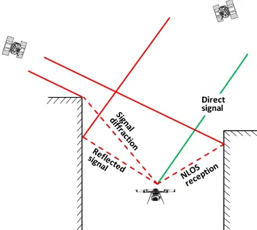
meth-Figure 1. Site-dependent GPS effects, which lead to systematic errors in the direct georeferencing of UAVs.
ods will be presented, which (1) predict challenging GPS condi-tions to avoid them during the flight-planning, and (2) mitigate site-dependent effects, if they can not be avoided.
1.2 Site-dependent GPS effects
An RTK-GPS positioning is based on GPS carrier-phase observa-tions, which are received at a stationary GPS master antenna and a moving rover antenna. In case of an RTK-GPS positioning of UAVs, the rover antenna is fixed on the UAV. One precondition for the estimation of the RTK-GPS positions is that carrier-phase observations of at least four satellites are received at both anten-nas (Hofmann-Wellenhof et al., 2008). However, it is well known that challenging GPS measurement conditions with obstacles in the signal path, such as single buildings, street canyons or vege-tation, can lead to a shadowing of GPS observations during kine-matic applications (Morales and Tsubouchi, 2007). Especially for UAV flights in urban areas, frequent losses of the GPS lock have to be expected. Certainly, observations of additional sensors (e.g. MEMS (Micro Electro Mechanical System) inertial sensors) can be used to bridge these GPS outages, but drift effects of these sensors deteriorate the positioning accuracy only a few seconds after the GPS loss of lock. For example in Mohamed et al. (2015) it was shown that deviations of 10-100 m have to be expected during a GPS outage of 30 s, when MEMS inertial sensors are used on a UAV.
Another effect that results from a satellite shadowing is a poor satellite geometry, which usually worsens the RTK-GPS position-ing accuracy. Thus, with the aim to provide high accuracies, GPS outages and a poor satellite geometry should be avoided as far as possible. This can be realized by considering the predicted GPS measurement conditions in the flight planning (see section 2).
Beside the shadowing effects, further site-dependent GPS effects have to be considered for UAV flights. These effects can be allo-cated to the near-field and the far-field of the antenna on the UAV platform.
The near-field denotes the immediate vicinity of the GPS antenna, mostly described as the first50cmaround the antenna, and has an influence on the antenna phase center characteristics. A possi-bility to reduce these near-field effects is the antenna calibration (W¨ubbena et al., 2000; Zeimetz and Kuhlmann, 2008).
The far-field includes all possible distant error sources, such as vegetation, the earth surface or buildings. The systematic errors, which result from the far-field are shown in Figure 1. These are
non-line-of-sight receptions (NLOS), signal diffraction and far-field multipath.
Far-field multipath effects are induced by reflecting surfaces in the surrounding of the antenna. The direct and reflected signals interfere in the antenna and lead to short periodic errors in both, the observation and coordinate domain (Hofmann-Wellenhof et al., 2008). If the direct signal path is blocked and only reflected signals arrive at the antenna, one speaks of non-line-of-sight (NLOS) receptions. Furthermore, satellite signals can also be diffracted at edges of an obstacle. This leads to a bending of the signal into the shadowed area. Thus, although the direct signal path is blocked, the affected signal arrives at the antenna (Brun-ner et al., 1999).
All these effects lead to systematic deviations in the observed GPS carrier phases and finally also in the estimated RTK-GPS positions. The error resulting from multipath effects is limited to one quarter of the carrier phase wavelength, which is about 5 cm for GPS L1 signals (Hofmann-Wellenhof et al., 2008). In contrast, NLOS reception has the potential to cause limitless er-rors (Strode and Groves, 2015). In practical applications the ef-fects of multipath, diffraction and NLOS reception are typically combined. As a result they also deteriorate the probability of a successful carrier phase ambiguity resolution, which is the key to high accuracies in an RTK-GPS positioning.
Summarizing, far-field errors make cm-accuracies impossible and should be avoided during UAV flights. If these errors cannot be avoided, for example when the UAV has to fly close to build-ings during mapping applications, simple strategies are necessary to mitigate these effects, to still allow for high GPS accuracies (see section 3).
1.3 UAV platform and data basis
In this paper we assume that the UAV platform is equipped with a direct georeferencing system, at least one digital camera and/or a small and lightweight laser scanner as well as a processing unit. Furthermore, we assume that the UAV platform is flying fully autonomous and that the surroundings of the UAV, such as the buildings along the trajectory, can either be mapped in near real-time during the flight or are known a priori from a coarse building model. The real-time onboard mapping can be based on a directly georeferenced incremental bundle adjustment of the collected im-ages or on a directly georeferenced 3D onboard laser scanning. An a priori 3D building model can be a LOD2 city model (level of detail 2, 3D model including roof structure), which is usually available in a global coordinate frame.
1.4 Related work
appli-cations, completely reliable methods to ensure a highly accurate direct positioning at the centimetre level even under challenging GPS measurement conditions are still missing.
The antenna environment can also be integrated into the a pri-ori mission planning process of UAV flights. In Gandor et al. (2015) a sophisticated open source flight planning tool is pre-sented, where, among other things, digital elevation models can be used to assess and optimize the waypoint planning. By fore-casting satellite positions using an almanac, the satellite visibil-ity and the expectable qualvisibil-ity of the satellite geometry along the trajectory can be determined and analyzed. This enables an im-provement of the waypoint planning in terms of flight time and preventing GPS outages due to obstructions. Nevertheless, as-sessing and adapting the waypoint planning in real time during the UAV flight is not possible yet and is subject to current re-search in this field.
1.5 Objectives
In this paper two strategies will be described and analyzed, which improve the direct positioning accuracies for UAV-based map-ping and surveying applications under challenging GPS measure-ment conditions:
1. Optimized selection of possible waypoints by assessing the available satellite constellation with respect to the UAV en-vironment.
2. Improvement of the positioning solution by using obstruc-tion adaptive elevaobstruc-tion masks (OAEMs).
In both approaches an integration of a known antenna surround-ing, which can come from an onboard near real-time mapping process or an a priori known 3D model of the UAV environment, into the mobile mapping process is proposed. On the one hand, we aim at an improvement of the UAV flight planning, to avoid GPS challenging environments. On the other hand, we introduce a method to mitigate NLOS reception and signal diffraction for the RTK-GPS processing during mobile mapping applications. In the following section (section 2) we first describe the quality assessment of possible waypoints. Afterwards we demonstrate the proposed method with simulated mobile mapping scenarios. In section 3 the determination of OAEMs is described and their impact on the quality of a positioning solution is shown for a kinematic field test.
2. GPS CONSTELLATION BASED FLIGHT PLANNING
In contrast to a remotely controlled flight, the UAV has to con-sider its 3D environment during an autonomous flight, to be able to safely navigate close to buildings, vegetation or moving ob-jects. Based on the user defined destination or an exploration algorithm as well as information about possible obstacles, in this case the flight path has to be adapted frequently and in real-time (Nieuwenhuisen and Behnke, 2015). Therefore, the 3D environ-ment of the planned flight path has to be known a priori and/or recorded during the flight. Since the absolute accuracies of the GPS positioning and the direct georeferencing are also dependent on the respective 3D environment of the UAV, we suggest to also include information about the expected GPS measurement con-ditions in the flight planning. Hence, a realistic and site-specific measure of the quality of the GPS measurement conditions is re-quired for a fully autonomous UAV waypoint flight.
2.1 Waypoint quality assessment
In general, the quality of possible GPS stations, which are way-points of a flight path here, can be assessed by computing posi-tion diluposi-tion of precision (PDOP) values (Misra and Enge, 2001). PDOP values are determined from the parameter cofactor matrix Qxxof the GPS position determination in a least squares
adjust-ment or a Kalman Filter approach:
Qxx=
whereX, Y, Zare the position parameters andtis the receiver clock error.
The geometry matrixA only includes the line-of-sight (LOS) vectors from the rover antenna to the respective GPS satellites. Therefore,Acan be determined without knowing any observa-tions, by using an approximate antenna position and the satellite coordinates, which can be calculated from the satellite ephemeris for a given observation time. Finally, the PDOP value results from equation 2.
P DOP =√qXX+qY Y +qZZ (2)
According to Hofmann-Wellenhof et al. (2008), the PDOP value is a measure for the quality of the satellite geometry. Generally speaking, the lower the PDOP, the better is the satellite constel-lation and the better is the predicted accuracy for the estimated GPS position at a given waypoint and a specific time. Neverthe-less, to be able to assess the actual satellite visibility along the flight path, the satellite obstruction due to the UAV environment has to be taken into account as well.
2.2 Visibility analysis
As mentioned in section 1.3, we assume that the 3D environment of the region of interest is either known a priori from a given 3D model or reconstructed during the UAV flight, based on the measurements of an onboard laser scanner or a digital camera. Using this information, the PDOP determination can be adapted according to the actual satellite obstruction at any waypoint of the planned flight path. With this in mind, the visibility analysis is performed in the following calculation steps: (1) The given 3D model of the environment is generalized with plane segments. (2) The LOS vectors from each waypoint of the planned flight path to all satellites are computed. (3) A vector-plane intersec-tion is calculated for all LOS vectors and planes of the 3D model. (4) All intersection points are tested, whether they are inside the restricting polygons for each plane, and whether they are between the waypoint and the satellites. If both tests are positive, the satel-lite signal would be obstructed at this waypoint and the respective satellite has to be discarded in the PDOP determination. (5) The positions of the satellites, identified as being visible, are used to compute the actual PDOP values to assess the quality of the re-spective waypoint.
Figure 2. Site-dependent GPS geometry map (colored dots) for a 2D-area between a building (right) and a simplified
representation of vegetation (left wall).
2.3 Simulations
To analyze the previously described procedure, simulations were performed. Therefore, a 3D-model of a real building and a sim-plified representation of its surrounding vegetation were used as obstacles. In Figure 2 and Figure 3, these obstacles are shown in gray. The plane segments in front of the building represent a tree and the plane on the left side of the building is a simplified representation of dense vegetation. Based on this information as well as the known GPS satellite positions at a given observation time, a 3D GPS geometry map can be produced. In Figure 2, this map is displayed as a 2D-grid for better illustration. The dif-ferent colors of the map are a measure for the available satellite constellation at possible waypoints of the UAV trajectory. Thus, this map can be used to improve the flight planning, according to the expected GPS measurement conditions at different way-points. Green points indicate a good satellite geometry and a probably high GPS positioning accuracy. In contrast, red points indicate poor accuracies or GPS losses of lock. In the flight plan-ning, which can be performed in real-time during the flight or in advance, it should be aimed at, to head for green waypoints at regular intervals. Otherwise long periods of GPS outages have to be expected.
In Figure 3 the PDOP values are shown for a real UAV trajectory along the building. This emphasizes, how the GPS measurement conditions can vary during a flight. The red waypoints of this trajectory should ideally be prevented as far as possible, to avoid long-term GPS losses of lock and to be able to provide high po-sitioning accuracies in the direct georeferencing.
3. IMPROVED POSITION ESTIMATION
Despite a proposed GPS constellation based flight planning it is not always possible to avoid poor GPS measurement conditions, when UAVs are used for mobile mapping applications. Often a comprehensive exploration or mapping of the region of interest requires flight paths close to buildings or vegetation (cf. Figure 3). To ensure a precise positioning of the UAV, we aim at an improvement of the position estimation by mitigating the most critical site-dependent effects, NLOS reception and signal
Figure 3. Site-dependent PDOP values (colored dots) for a UAV trajectory along a building (right) and a simplified representation
of vegetation (left wall)
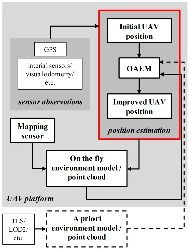
Figure 4. Schematic description of the mobile mapping process including the improved position estimation by using OAEMs.
3.1 Determination of obstruction adaptive elevation masks
In the first step, an initial antenna positionXrand its accuracy
ΣXr is determined with all available observations. Afterwards, the line-of-sight vectorsdi =ei ni ui
T
from this initial antenna position to every pointXiof the point cloud are
com-puted in a local topocentric coordinate system. Next, the azimuth and elevation angles(αi, βi)with respect to the initial antenna
positionXrare determined according to
αi= arctan
To relate the computed elevation values to the obstacles in the antenna surrounding, theβivalues are allocated to an azimuthal
grid with a predefined cell width ofδ = 0.5◦. For every cellc
the highest elevation angleβ¯cis identified according to (5). In
the case that a cell is not filled, i.e. no obstructions are present for this azimuth area ,β¯cis set to0◦.
The intention of the cell wise determinedβ¯cvalues is to identify
satellite signals that are received without a direct line-of-sight. Since the accuracy of the elevation anglesσ¯βc, and thereby also the correctness of the identification, directly depends on the accu-racy of the initial antenna positionΣXr =
σer σnr σur
T
, theβ¯cvalues have to be adjusted with respect toΣXr and the height and distance of the respective obstruction source. For this purpose,σ¯βcis used as an adjustment value for every cellc, to compensate inaccuracies in the identifiedβ¯c values. Therefore,
the accuracy ofβ¯cis determined by propagatingΣXr according to the error propagation law:
σ¯βc=
p
F·ΣXr·F
T (6)
whereFcontains of the partial derivatives of (4) in relation to the components of the respective LOS vector. Afterwards, the cell wise adjusted elevation anglesβˆcare computed by
ˆ
βc= ¯βc+σβ¯c. (7)
The magnitude ofσ¯βc depends on (i) the height and distance of the obstacle and (ii) the accuracy of the initial antenna position. Hence, in order to avoid values higher thanσ¯βc = 5
◦,
indepen-dent from the obstacle dimensions, we estimated that the initial antenna position should be known with an accuracy better than approximately20cm. For ambiguity fixed RTK positions, this can easily be achieved. Nevertheless, in the case of float or even code solutions this is different. In these cases, the initial antenna position should be determined by using the data of additional sen-sors, such as inertial sensors or visual odometry (Scaramuzza and Fraundorfer, 2011).
After the cell wise adjustment of theβ¯cvalues is performed, the
OAEM is represented by a fully populated360◦index vector that
can be used as a Look-Up-Table to identify satellite signals that are subject to NLOS reception or signal diffraction. In the RTK-GPS position determination, for all received satellite signals the elevation and azimuth angles(αj, βj)to the respective satellites
are computed according to (3) and (4). In the case that an eleva-tion angleβjis lower than the elevation angleβ¯c, which is taken
from the cellcassociated to the azimuthαj, the satellite signal is
either received by NLOS reception or the signal is diffracted at an edge of an obstacle. By excluding these satellites from the coor-dinate estimation process, a more precise and robust positioning can be performed. Nevertheless, it should be noted that far-field multipath effects are not mitigated by the presented approach.
3.2 Field tests
In order to evaluate the performance of OAEMs, a kinematic field test was performed in a test area, where both, good and bad GPS measurement conditions can be found. In the surrounding of the trajectory a machine hall and a shed with heights of approxi-mately 9.75m and 8.90m degraded the GPS measurement con-ditions. In advance to the field test, the area was measured with a terrestrial laser scanner (TLS) and the point clouds where trans-formed into the global coordinate frame.
Instead of real UAV data we used a test set up, which consists of an AX1202GG antenna on a 2 meter prism pole connected to a GPS1200 receiver. Furthermore, a360◦prism of type
Le-ica GRZ122 was mounted under the antenna. This enabled us to perform controlled reference measurements with a Leica TS16 tacheometer in a stop&go mode. Since the tacheometer measure-ments were only triggered during the stop phase, latency times between angular and distance measurements during the motion of the UAV did not have to be taken into account and the refer-ence values could clearly be related to the actual antenna posi-tions. Before the kinematic test, the position of the tacheometer was determined via free stationing with an accuracy of 3mm for the east and north components and 5mm for the up component respectively.
We are aware that this test set up and this measurement procedure do not simulate a UAV flight in a completely realistic way. Vibra-tions, electromagnetic disturbances or high dynamic motions are effects that usually influence the data collection during an UAV flight and which are not present during the field test. Neverthe-less, in Eling et al. (2015) it was demonstrated, that accuracies in the order of the expected 1-3cm can be achieved during the flight, if appropriate countermeasures, such as shielding of the process-ing unit, are performed. Thus, the RTK solution, derived from the data collected with the presented test set up, can be used to assess the effectiveness of the proposed approach.
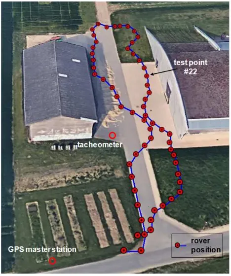
During the field test, raw GPS observations were recorded with a sampling rate of 10Hz and the rover system was moved along the trajectory, which consists of 60 points (cf. Figure 5). The trajec-tory was planned along both buildings with different distances to the walls, to cover points with good, as well as bad GPS measure-ment conditions. In every stop phase of approximate 15 to 20 sec-onds duration, the prism pole was levelled and fixed with a pole tripod. Afterwards the reference measurement of the tacheometer was triggered.
Figure 5. Aerial image of the test area ( cGoogle Earth 2017). The red dots connected by the blue line denote the test points on
the trajectory. The red circles mark the positions of the tacheometer and the GPS master station.
3.3 Evaluation
In a first step, the initial antenna positions of the 60 test points were determined in a baseline solution for the original data set with all available observations using the open source software packageRTKLIB(Takasu and Yasuda, 2009). Therefore, dual-frequency GPS measurements were used and a standard iono-sphere model and the Saastamoinen tropoiono-sphere model were ap-plied. The standard elevation mask was set to5◦and the integer
phase ambiguities were estimated and fixed continuously. Be-sides the positioning solution, also the accuracies of the initial antenna positions were provided by the software. The accuracies varied in a range of 3cm to 13cm and thus fulfil the requirements stated in section 3.1.
For all of the initial antenna positions the OAEMs were deter-mined according to the process described in section 3.1, based on the georeferenced TLS point cloud. In Figure 6 the skyplot of test point #22 (c.f. Figure 5) including the respective OAEM is shown exemplarily. By comparing the satellite positions and the elevation mask boundary in the skyplot of point #22, the satel-litesG23andG30can be identified as being obstructed by the right building. Hence, these satellite signals are either subject to NLOS reception or they are diffracted at the edge of the building.
After the determination, the OAEMs were applied to the original GPS observation data files. In a decision step all satellites without a direct line-of-sight were identified. Finally, these satellites were excluded from the data base and the original observation file was rewritten and afterwards reprocessed inRTKLIB, using the same parameter settings as for the initial baseline solution.
Since the results should be assessed by comparison to the terres-trial reference solution, which was derived from the
75
60
45
30
15
0
30
210
60
240
90
270
120
300
150
330
180
0
G05
G02
G06
G30
G09 G23 G16
G07
Figure 6. Skyplot of test point #22. The black dashed line represent the OAEM determined for this initial antenna position.
ter measurements, the observation times with simultaneous mea-surements had to be identified. This time synchronization was realized by using the time stamps of the GPS and tacheometer observations. Furthermore, the up component of the reference solution was corrected for the vertical offset between the antenna reference point and the prism center.
In Figure 7 the differences in the up component to the terrestrial reference solution are shown for the original and the modified data sets. In the bottom panel, the test points where satellites were excluded by applying the determined OAEMs, are marked with black circles.
The comparison of the results shown in Figure 7 clearly demon-strates that the differences to the terrestrial reference solution decrease after the OAEMs are applied to the data set. Particularly between the two buildings the positional accuracy is improved significantly. For the modified data set the deviations in the up-component vary between maximum values of ±2.5cm, whereas the original data set leads to coordinate differences between−18.5cmand14.3cm. The same holds for the east and north component respectively. After the OAEMs are applied, the combined RMS values for the coordinate differences of the test points are below one centimetre in all coordinate components (cf. Table 1). In comparison to the original RMS values, this corresponds to an improvement of up to82%.
East [m]
North [m]
Up [m]
RMS Original data 0.025 0.036 0.045 RMS Modified data 0.008 0.007 0.008
Table 1. Deviations of test points to the terrestrial reference solution
0 20 40 60 80 100
up differences [cm] (original data)
−15
up differences [cm] (modified data)
−15
Figure 7. Differences of the determined up coordinates to the reference solution for the original (top) and modified (bottom) data set. The black circles in the bottom panel mark points where
satellites were excluded by applying the determined OAEMs.
affected signals from the RTK-GPS position estimation, by using the OAEMs.
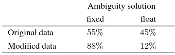
Ambiguity solution
fixed float
Original data 55% 45%
Modified data 88% 12%
Table 2. Success rate of ambiguity fixing
4. CONCLUSIONS
In this paper two real-time capable and easy to implement strate-gies to improve the accuracy of the direct georeferencing of UAVs under challenging GPS measurement conditions were presented. On the one hand, the determination of GPS geometry maps was described. Therein, a visibility analysis of the satellite signals can be performed, to determine realistic PDOP values that can be used to detect and avoid GPS challenging environments. For a simulated UAV flight, the GPS geometry maps were derived from 3D building models and their use to improve the flight planning process of UAVs was presented.
On the other hand, for the case that challenging environments cannot be avoided during the flight, elevation masks that are adap-tive to the obstructions in the surrounding of the current UAV position were proposed. These OAEMs are derived from georef-erenced 3D point clouds and can be used to identify GPS obser-vations that are subject to NLOS reception or signal diffraction. In a field test, the RTK-GPS positions of 60 points of a trajectory where compared to known reference coordinates. For the original data set, the deviations at 11 of the 60 points exceeded values of 5cmwith maximum deviations of−18.5cmand14.3cm. After the proposed method was applied, the coordinate differences for all points could be reduced to maximum values of±2.5cm. Ad-ditionally, the success rate of the ambiguity resolution could be improved from55%to88%by excluding NLOS reception and signal diffraction.
Both strategies demonstrate that the integration of the UAV envi-ronment in terms of 3D models or point clouds, prior or during the UAV flight, enhances the direct georeferencing accuracies for UAV-based mapping and surveying applications.
Currently, the authors work on the implementation of the pro-posed methods in the georeferencing system of a real UAV, as well as on the integration of online available 3D building mod-els with the data of the onboard mapping sensors. The aim is to realize a fully automated UAV flight with a cm-accurate direct positioning in near real-time, even under challenging GPS mea-surement conditions.
ACKNOWLEDGEMENTS
This work was funded by the DFG (Deutsche Forschungsgemein-schaft) under the project number 1505 ”Mapping on Demand”. The authors wish to express their gratitude for this support.
References
Aibotix, 2017. Aibotix GmbH, Ludwig-Erhard-Str. 14, 34131 Kassel, Germany.
B¨aumker, M., Przybilla, H.-J. and Zurhorst, A., 2013. Enhance-ments in UAV flight control and sensor orientation. In:The In-ternational Archives of Photogrammetry, Remote Sensing and Spatial Information Science, Vol. XL-1/W2, UAV-g 2013, Ro-stock, Germany, pp. 33–38.
Bl´aha, M., Eisenbeiss, H., Grimm, D. and Limpach, P., 2011. Di-rect georeferencing of UAVs. In:The International Archives of Photogrammetry, Remote Sensing and Spatial Information Sci-ence, Vol. XL-1/W2, UAV-g 2011, Zurich, Switzerland, pp. 1– 6.
Brunner, F. K., Hartinger, H. and Troyer, L., 1999. GPS signal diffraction modelling: the stochastic SIGMA-∆model. Jour-nal of Geodesy73(5), pp. 259–267.
Droeschel, D., Holz, D. and Behnke, S., 2014. Omnidirectional Perception for Lifgtweight MAVs using a Continously Rotat-ing 3D Laser Scanner. PFG - Photogrammetrie, Fernerkun-dung, Geoinformation5, pp. 451–464.
Eling, C., Klingbeil, L., Wieland, M. and Kuhlmann, H., 2014. Direct Georeferencing of Micro Aerial Vehicles - Sys-tem Design, SysSys-tem Calibration and First Evaluation Tests.
PFG - Photogrammetrie, Fernerkundung, Geoinformation4, pp. 227–237.
Mapping System for Remote Sensing and Surveying Applica-tions. ISPRS - International Archives of the Photogrammetry, Remote Sensing and Spatial Information SciencesXL-1/W4, pp. 233–239.
Gandor, F., Rehak, M. and Skaloud, J., 2015. Photogrammet-ric Mission Planner for RPAS. The International Archives of Photogrammetry, Remote Sensing and Spatial Information Sci-ences40(1), pp. 61.
Gerke, M. and Przybilla, H.-J., 2016. Accuracy Analysis of Pho-togrammetric UAV Image Blocks: Influence of Onboard RTK-GNSS and Cross Flight Patterns. Photogrammetrie - Fern-erkundung - Geoinformation2016(1), pp. 17–30.
Grenzd¨orffer, G., Naumann, M., Niemeyer, F. and Frank, A., 2015. Symbiosis of UAS photogrammetry and TLS for sur-veying and 3D modeling of cultural heritage monuments - a case study about the cathedral of St. Nicholas in the city of Greifswald. In:The International Archives of the Photogram-metry, Remote Sensing and Spatial Information Sciences, Vol. XL-1/W4, UAV-g 2015, Toronto, Canada, pp. 91–96.
Groves, P. D., Jiang, Z., Wang, L. and Ziebart, M. K., 2012. In-telligent Urban Positioning using Multi-Constellation GNSS with 3d Mapping and NLOS Signal Detection. In: Proceed-ings of the 25th International Technical Meeting of the Satel-lite Division of The Institute of Navigation (ION GNSS 2012), Nashville, TN, USA, September 17-21.
Hofmann-Wellenhof, B., Lichtenegger, H. and Wasle, E., 2008.
GNSS–global navigation satellite systems: GPS, GLONASS, Galileo, and more. Springer-Verlag, Wien, NewYork, NY, USA, pp. 154–158.
Klingbeil, L., Nieuwenhuisen, M., Schneider, J., Eling, C., Droeschel, D., Holz, D., L¨abe, T., F¨orstner, W., Behnke, S. and Kuhlmann, H., 2014. Towards autonomous navigation of an UAV-based mobile mapping system. In: 4th International Conference on Machine Control & Guidance, Braunschweig, Germany, pp. 136–148.
Lohmar, F. J., 1999. Optimized Planning of GPS-based Mea-surements on Points with Restricted Satellite Visibilities. In:
Proceedings of the 12th International Technical Meeting of the Satellite Division of The Institute of Navigation (ION GPS 1999), Nashville, TN, USA, September 14-17, pp. 85–90.
MaVinci, 2017. MaVinci GmbH, Opelstr. 8a, 68789 St. Leon-Rot, Germany. http://www.mavinci.de/de/pro-version/.
Meguro, J.-i., Murata, T., Takiguchi, J.-i., Amano, Y. and Hashizume, T., 2009. GPS multipath mitigation for urban area using omnidirectional infrared camera. IEEE Transactions on Intelligent Transportation Systems10(1), pp. 22–30.
Merz, T. and Kendoul, F., 2011. Beyond visual range obstacle avoidance and infrastructure inspection by an autonomous he-licopter. In:IEEE/RSJ International Conference on Intelligent Robots and Systems, IROS 2011, San Francisco, USA.
Misra, P. and Enge, P., 2001.Global Positioning System. Ganga-Jumana Press, Lincoln, Massachusetts, USA, pp. 182–187.
Mohamed, H. A., Hansen, J. M., Elhabiby, M. M., El-Sheimy, N. and Sesay, A. B., 2015. Performance characteristic MEMS-based IMUs for UAVs navigation. In:International Archives of the Photogrammetry, Remote Sensing and Spatial Informa-tion Sciences, Vol. XL-1/W4, UAVg-2015, Toronto, Canada, pp. 337–343.
Morales, Y. and Tsubouchi, T., 2007. DGPS, RTK-GPS and starfire DGPS performance under tree shading environments. In: ICIT ’07. IEEE International Conference on Integration Technology, Shenzhen, China, pp. 519–524.
Moreau, J., Ambellouis, S. and Ruichek, Y., 2017. Fisheye-based method for GPS localization improvement in unknown semi-obstructed areas.Sensors17(1), pp. 119.
Nieuwenhuisen, M. and Behnke, S., 2015. 3D Planning and Trajectory Optimization for Real-time Generation of Smooth MAV Trajectories. In: Proceedings of the European Confer-ence on Mobile Robots (ECMR), Lincoln, UK.
Peterman, V., 2015. Landslide activity monitoring with the help of Unmanned Aerial Vehicle. In: The International Archives of the Photogrammetry, Remote Sensing and Spatial Informa-tion Science, Vol. XL-1/W4, UAV-g 2015, Toronto, Canada, pp. 447–451.
Rehak, M., Mabillard, R. and Skaloud, J., 2014. A micro aerial vehicle with precise position and attitude sensors.PFG - Pho-togrammetrie, Fernerkundung, Geoinformation 4, pp. 239– 251.
Scaramuzza, D. and Fraundorfer, F., 2011. Visual odometry [tuto-rial].IEEE robotics & automation magazine18(4), pp. 80–92.
Schneider, J., Eling, C., Klingbeil, L., Kuhlmann, H., F¨orstner, W. and Stachniss, C., 2016. Fast and effective online pose es-timation and mapping for UAVs. In:Proceedings of the IEEE Int. Conf. on Robotics & Automation (ICRA), Stockholm, Swe-den.
senseFly, 2017. senseFly SA, Route de Gen`eve 38, 1033 Cheseaux-Lausanne, Switzerland.
Strode, P. R. R. and Groves, P. D., 2015. GNSS multipath detec-tion using three-frequency signal-to-noise measurements.GPS Solutions20, pp. 1–14.
Takasu, T. and Yasuda, A., 2009. Development of the low-cost RTK-GPS receiver with an open source program package RTKLIB. In: International symposium on GPS/GNSS, ICC Jeju, Korea, pp. 4–6.
Tscharf, A., Rumpler, M., Fraundorfer, F., Mayer, G. and Bischof, H., 2015. On the use of UAVs in mining and archael-ogy - geo-accurate 3d reconstructions using various platforms and terrestrial views. In: ISPRS Annals of the Photogram-metry, Remote Sensing and Spatial Information Sciences, Vol. II-1/W1, UAV-g 2015 conference, Toronto, Canada, pp. 15–22.
Wang, L., Groves, P. D. and Ziebart, M. K., 2013. GNSS Shadow Matching: Improving Urban Positioning Accuracy Using a 3D City Model with Optimized Visibility Scoring Scheme. Navi-gation60(3), pp. 195–207.
W¨ubbena, G., Schmitz, M., Menge, F., B¨oder, V. and Seeber, G., 2000. Automated absolute field calibration of GPS antennas in real-time. In:Proceedings of the 13th International Technical Meeting of the Satellite Division of the Institute of Navigation (ION GPS 2000), September 19-22, Salt Lake City, UT, USA, pp. 2512–2522.